
Abstract
Recent studies have shown that the combination of external dampers and cross-ties can overcome their respective deficiencies while retaining their respective merits. Inspired by the advantages of a viscous damper (VD) and a cross-tie on a single stay cable, the coupled damping effect of a parallel-connected viscous mass damper (PVMD) and a grounded cross-tie on a single stay cable is investigated in this paper. The complex wave number equations of the cable–PVMD–cross-tie system are first formulated through the complex modal analysis. Subsequently, the asymptotic and iterative complex wave numbers are compared to evaluate the applicability of the asymptotic and iterative solutions. Furthermore, parametric studies are carried out to investigate the effects of the stiffness coefficients and the installation positions of the cross-tie on the first supplemental modal damping ratio and frequency of the cable. Finally, the installation positions of the cross-tie are optimized to achieve the optimal vibration control of the cable with the PVMD and the cross-tie.
Introduction
In recent years, structural vibration control has received extensive attentions, especially the vibration control of stay cables in cable-stayed bridges.1-3 Stay cables, as the critical load-bearing component of cable-stayed bridges, are highly vulnerable to environmental excitations such as wind, wind-rain, and parametric excitations.4-6 Frequent vibrations may shorten the cable life and impair public confidence in the safety of cable-stayed bridges. Consequently, several countermeasures have been proposed to suppress the excessive vibrations of stay cables, including changing the surface characteristics of the cable to improve its aerodynamic characteristics,7,8 connecting cables via the cross-tie, 9 and attaching external dampers on cables.10-12 Among these countermeasures, attaching external dampers on cables is the most common and effective measure. However, it is difficult to effectively mitigate vibrations for super-long cables in large-span cable-bridges, such as the longest cable in the Stonecutters Bridge (536 m) and the longest cable in the Sutong Bridge (577 m). Hence, it is necessary to combine available countermeasures to efficiently mitigate these cable vibrations.13-15
To improve the control performance of passive dampers, a semi-active control strategy using magneto-rheological (MR) damper is proposed. 16 MR dampers, as one of the most representative semi-active control devices, will provide a semi-active control method for stay cables to balance effectiveness and practicality. It is found that the negative stiffness characteristic of the semi-active MR dampers helps to improve the supplemental modal damping ratio of stay cables.17,18 Inspired by the advantages of the negative stiffness characteristic of the semi-active MR dampers, the passive negative stiffness dampers (NSDs), including pre-spring NSDs19,20 and magnetic NSDs,21,22 have received more attention in the field of cable vibration control. Moreover, a series of theoretical and experimental investigations have proved the effectiveness of NSDs in mitigating cable vibrations.23-25 Shi et al.23,24 demonstrated that the negative stiffness characteristic of the NSDs was conducive to providing more sufficient supplemental damping than that of passive viscous dampers. Javanbakht et al. 25 verified that the NSDs presented superior performance over the conventional positive stiffness dampers (PSDs) in cable vibration control. However, excessive passive negative stiffness may induce the instability problem to the cable. 22 Recent studies have shown that passive VD and inertial mass elements are connected in parallel to consist of a parallel-connected viscous mass damper (PVMD), which can improve the vibration control performance of structures.26-29 Compared with conventional VD, PVMD can provide more supplemental damping for stay cables, which has been verified by both theoretical analyses30-33 and experimental investigations.34,35
A combination strategy of using both cross-ties and external dampers is also proposed to suppress the cable vibrations. Connecting cables via cross-ties can effectively enhance the in-plane stiffness and frequencies of stay cables,36-38 while it is difficult to effectively improve the supplemental damping of stay cables. 39 It has been found that the hybrid techniques of using cross-ties and dampers can overcome their respective deficiencies while retaining their respective merits.40-43 Among them, Zhou et al. 43 simplified the cross-ties as a discrete spring to investigate the damping and frequency of a taut cable with a damper and a spring. Di et al. 44 proposed a simplified analytical method to investigate the effects of cross-ties on the dynamics of a hybrid cable network system. Furthermore, recent studies have shown that when two dampers are installed at opposite cable ends, the combined damping effect is approximately the sum of the contributions from each damper.45-47 In addition, Yang et al. 48 explored a novel optimal design of two viscous dampers near to a cable anchorage, which can achieve a potential improvement in damping ratios of cables for lower and higher vibration modes. Thus, the combination strategy of using two dampers, either or a damper and a cross-tie, can achieve superior cable vibration control performance over that of using a single damper.
Inspired by the advantages of a VD and a grounded cross-tie on a single stay cable, the coupled damping effects of a single stay cable with a parallel-connected viscous mass damper (PVMD) and a grounded cross-tie are further investigated in this paper. The paper is organized as follows. Firstly, the complex wave number equations of the cable–PVMD–cross-tie system are formulated by using the complex modal analysis. Then, the asymptotic and iterative solutions for the PVMD and the grounded cross-tie, either at the same cable end or at opposite cable ends, are obtained, respectively. Furthermore, the applicability of the iterative solution is evaluated, and the coupled damping effect of the cable with a PVMD and a cross-tie is further discussed when the cross-tie is connected at different positions of the cable. Finally, the maximum first supplemental modal damping ratio of a cable with a PVMD and a grounded cross-tie is highlighted when the cross-tie is installed at the cable mid-span.
Formulation of the cable–PVMD–cross-tie system
A taut cable with a PVMD and a grounded cross-tie is shown in Figure 1. The length, the tension, and the mass per unit length of the cable are denoted as l, T, and m, respectively. The coordinate system defines that the x-axis and the u-axis are along the cable chord and the transverse direction. The PVMD and the cross-tie are respectively fixed at distances x1 and x2 from the left end of the cable (x2≥x1). The distance between the cross-tie and the right end of the cable is denoted as A taut cable with a PVMD and a grounded cross-tie.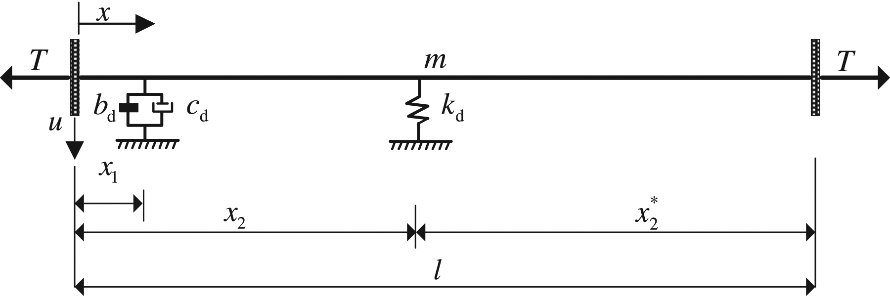

Equation (1) satisfies the boundary conditions at the cable ends, and there is

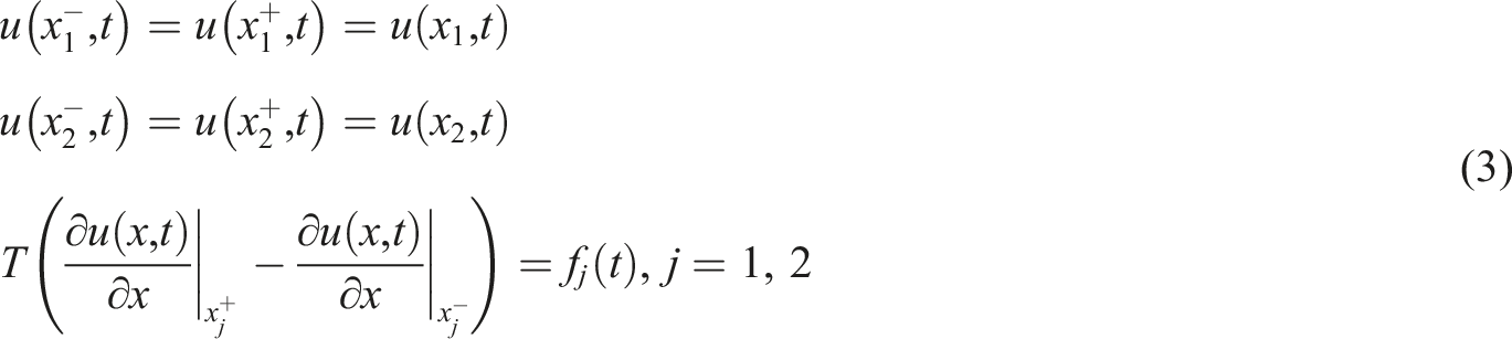
At the damper and the cross-tie location, u(x) needs to satisfy the following boundary conditions
For free vibration of the cable, the cable transverse displacement, the force of the PVMD, and the force of the cross-tie can be expressed as


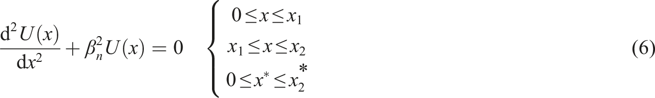
Substituting equation (4) into equation (1), U(x) in each span needs to satisfy a homogeneous equation45,46
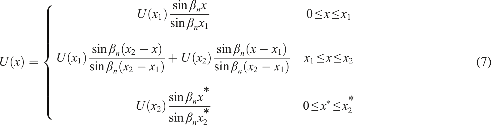
The general solution of equation (6) can be written in the form
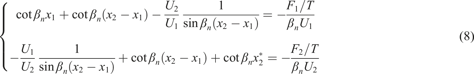
Substituting U1/U2 from the second equation of equation (8) into the first equation of equation (8) and rearranging, the characteristic equation of the wave number β
n
can be derived as
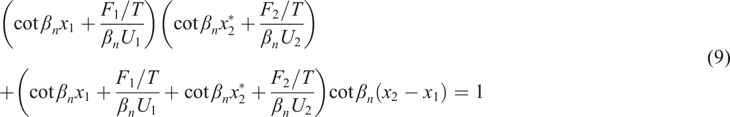
The forces of the PVMD and the cross-tie can be expressed as

When the PVMD and the grounded cross-tie are installed at the same cable end, that is, x1≤x2<l/2, substituting equation (10) into equation (9), equation (9) can be rearranged to the form relating to x1 and x2 as


When the PVMD and the grounded cross-tie are installed at opposite cable ends, that is,


The PVMD and the grounded cross-tie at the same cable end
Asymptotic solution and iterative solution
The iterative solution of the complex wave number
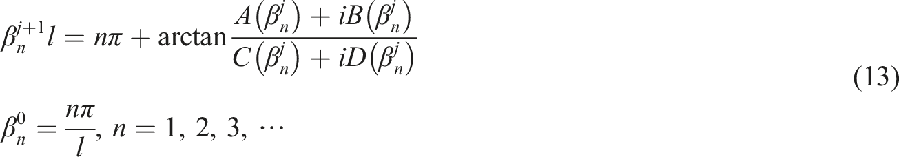

The following assumptions are introduced
45
: (1) the PVMD and the cross-tie are installed near the left cable end, that is,

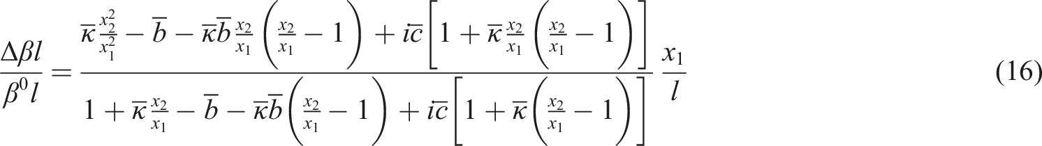
Substituting equation (16) into equation (14), the asymptotic solution of the n
th
supplemental modal damping ratio of the cable can be derived as
Comparison of asymptotic and iterative solutions
The PVMD and the grounded cross-tie are installed at the positions of x1=1%l and x2=2%l from the left cable end, respectively. Figure 2 compares the asymptotic and iterative complex wave numbers of a cable with a PVMD and a cross-tie when the dimensionless stiffness coefficient of the cross-tie κ=0.01/(nπx1/l). When the dimensionless inertial mass remains constant and the dimensionless damping coefficient of PVMD increases from zero to infinity, the complex wave number traces a semicircle with a positive imaginary part. The semicircle trace starts from an undamped frequency and eventually terminates at a clamped frequency on the real axis. The top point of the semicircle trace suggests the maximum supplemental modal damping ratio of the cable. It can be seen from Figure 2 that the maximum supplemental modal damping ratio of the cable gradually increases with the increase of the inertial mass of the PVMD. Moreover, the asymptotic complex wave number is in good agreement with the iterative complex wave number when the dimensionless inertial mass χ=0/(nπx1/l), χ=0.3/(nπx1/l), and χ=0.6/(nπx1/l). However, the asymptotic and iterative complex wave numbers significantly deviate from each other for the large inertial mass χ=0.9/(nπx1/l), and the basic assumption of the asymptotic solution is no longer valid under this circumstance. Hence, the iterative solutions are used to accurately predict the maximum supplemental modal damping ratio of the cable as well as the corresponding parameters of the PVMD and the cross-tie in the following discussions. Comparisons of the asymptotic and iterative complex wave numbers of a cable with a PVMD and a grounded cross-tie (x1=1%l, x2=2%l, κ=0.01/(nπx1/l)).
Parametric studies
Figure 3 shows the variations of the first supplemental modal damping ratio of a cable with a VD (PVMD) and a grounded cross-tie with the damping coefficient of the VD (PVMD) under the various stiffness coefficients of the cross-tie. It can be observed from Figure 3 that the maximum supplemental damping ratio of a cable with a PVMD and a grounded cross-tie is significantly increased compared with that of a cable with a VD and a grounded cross-tie, which indicates the coupled damping effect of a PVMD and a grounded cross-tie on a stay cable is superior to that of a VD and a grounded cross-tie on a stay cable. However, increasing the dimensionless stiffness coefficient of the cross-tie has negative effects on improving the maximum supplemental damping ratio of the cable. Variations of the first modal damping ratio of the cable with the damping coefficient under various stiffness coefficients of the cross-tie (x1=1%l, x2=2%l).
Figure 4 shows the variations of the first supplemental modal damping ratio of a cable with a VD (PVMD) and a grounded cross-tie with the damping coefficient of the VD (PVMD) under various installation positions of the cross-tie. It can be seen from Figure 4 that the maximum supplemental modal damping ratio of the cable decreases with the cross-tie moving away from the VD or the PVMD. Thus, when the PVMD and the grounded cross-tie are installed at the same cable end, the increase of installation length of the cross-tie is unfavorable to the damping improvement of the cable. Variations of the first modal damping ratio of the cable with the damping coefficient under various installation positions of the cross-tie (x1=1%l, κ=0.05/(nπx1/l)).
The PVMD and the grounded cross-tie at opposite cable ends
Asymptotic solution and iterative solution
Similar to the case of a PVMD and a ground cross-tie at the same cable end, when the PVMD and the grounded cross-tie are installed at opposite cable ends, the iterative solution of the complex wave number β
n
is also obtained by the fixed-point iteration method,
49
in which the iterative equation is given by
Comparison of asymptotic and iterative solutions
The PVMD and the grounded cross-tie at opposite cable ends are installed at the positions of x1=1%l from the left cable end and Comparisons of the asymptotic and iterative complex wave numbers of a cable with a PVMD and a grounded cross-tie (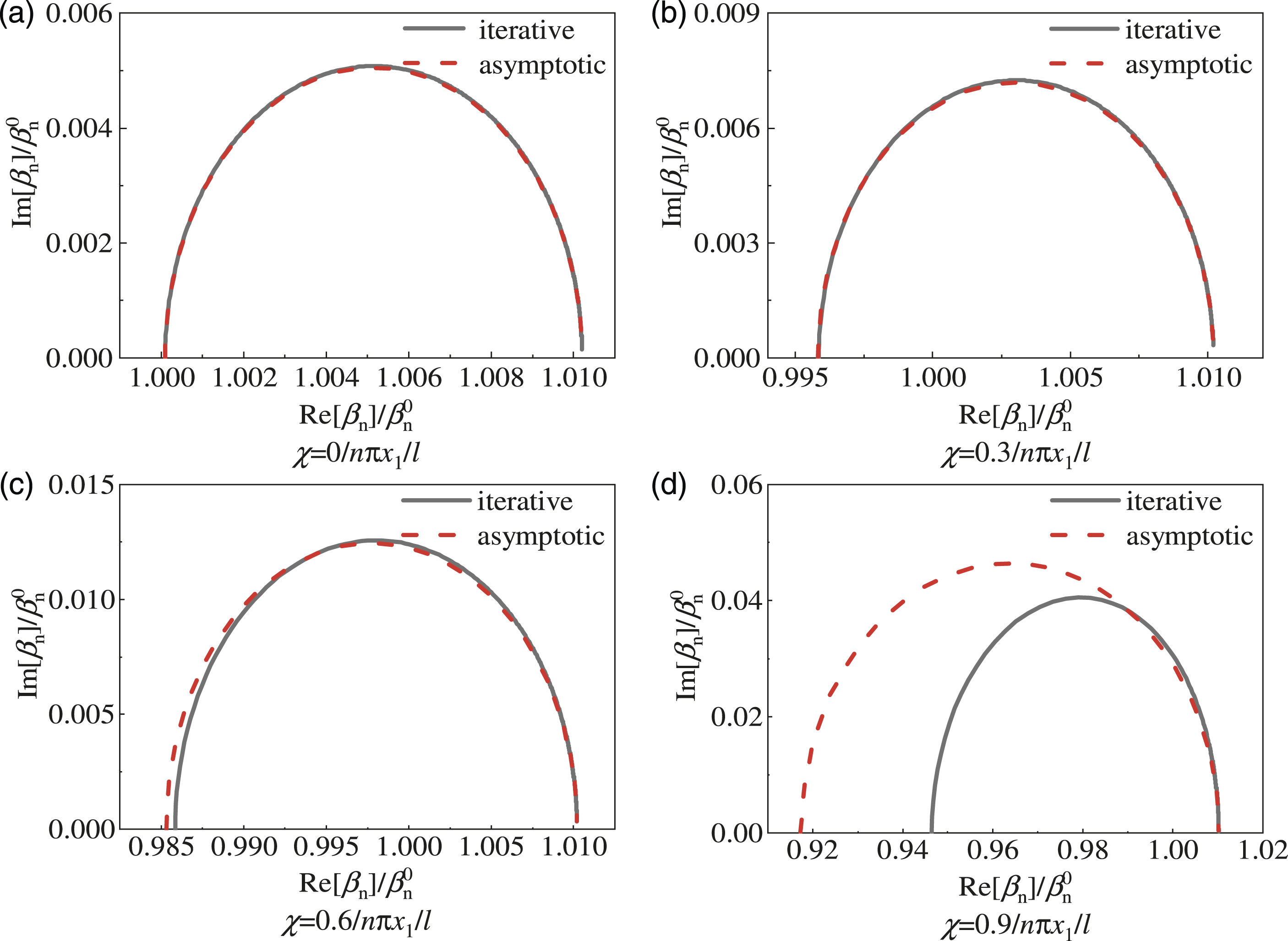
Parametric studies
Figure 6 shows the variations of the first supplemental modal damping ratio of the cable with a VD (PVMD) and a grounded cross-tie with the damping coefficient of the VD (PVMD) under various stiffness coefficients of the cross-tie. As illustrated in Figure 6, the maximum supplemental damping ratio of a cable with a PVMD and a grounded cross-tie is significantly increased compared with that of a cable with a VD and a grounded cross-tie, which indicates the coupled damping effect of a PVMD and a grounded cross-tie on a stay cable is superior to that of a VD and a grounded cross-tie on a stay cable. Moreover, increasing the dimensionless stiffness coefficient of the cross-tie is conducive to improving the maximum supplemental modal damping ratio of the cable. Variations of the first supplemental modal damping ratio of the cable with the damping coefficient under different stiffness coefficients of the cross-tie 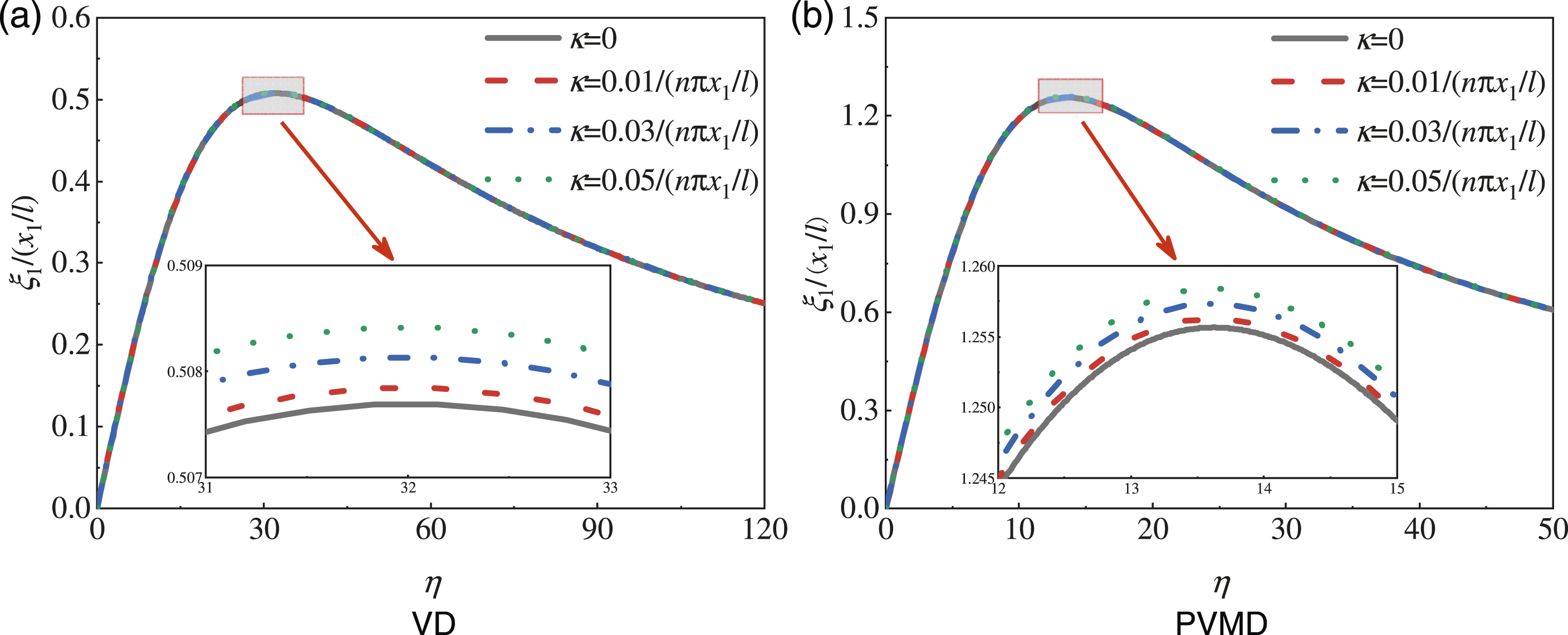
Figure 7 shows the variations of the first supplemental modal damping ratio of the cable with a VD (PVMD) and a grounded cross-tie with the damping coefficient of the VD (PVMD) under various installation positions of the cross-tie. It can be seen from Figure 7 that the maximum supplemental modal damping ratio of the cable slightly increases with the cross-tie moving away from the right cable end. Consequently, when the PVMD and the grounded cross-tie are installed at opposite cable ends, the increase of installation length of the cross-tie helps to achieve the damping improvement of the cable. Variations of the first modal damping ratio of the cable with the damping coefficient under various installation positions of the cross-tie (x1=1%l, κ=0.05/(nπx1/l)).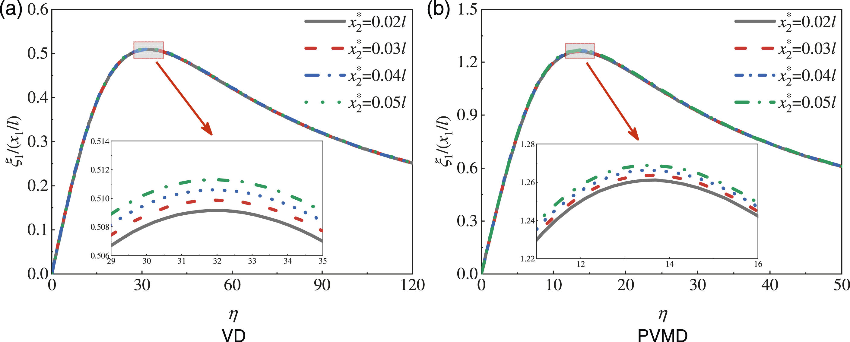
Optimization for the installation positions of the cross-tie
Optimal installation positions of the cross-tie
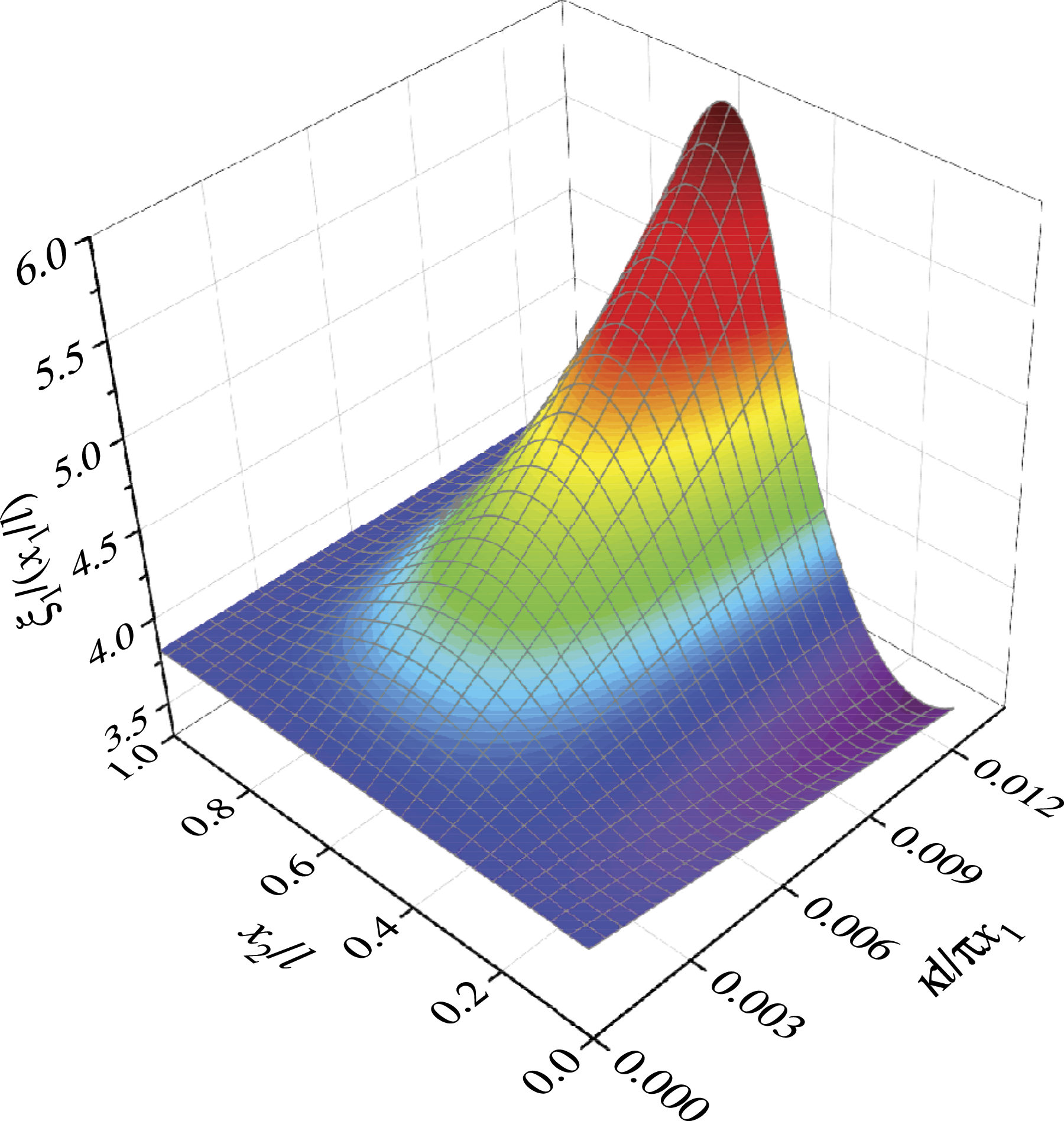
To analyze the effects of the installation positions of the cross-tie on the damping of a cable with a PVMD and a grounded cross-tie, the optimization for the installation positions of the cross-tie is carried out in this section. Figure 8 shows the variations of the first supplemental modal damping ratio of the cable with the installation positions of the cross-tie and the damping coefficients of the PVMD. It can be observed from Figure 8 that the first modal damping ratio of the cable reaches its maximum value when the installation position of the cross-tie is x2/l=0.51 and the damping coefficient of the PVMD is η=0.26. The variations of the first supplemental modal damping ratio of the cable with the installation positions and the stiffness coefficients of the cross-tie are further illustrated in Figure 9. It can be seen from Figure 9 that the first supplemental modal damping ratio of the cable reaches the maximum when the cross-tie is installed at the cable mid-span, in which the first supplemental modal damping ratio of the cable increases significantly with the increase of the stiffness coefficient of the cross-tie. Thus, the cable mid-span is the optimal installation position for the cross-tie to improve the vibration control performance of the cable for the first mode. Variations of the first supplemental modal damping ratio of the cable with the installation positions of the cross-tie and the damping coefficients of the PVMD (χ=0.9/(nπx1/l), κ=0.01/(nπx1/l)). Variations of the first supplemental modal damping ratio of the cable with the installation positions and the stiffness coefficients of the cross-tie (χ=0.9/(nπx1/l), η=0.26/(nπx1/l)).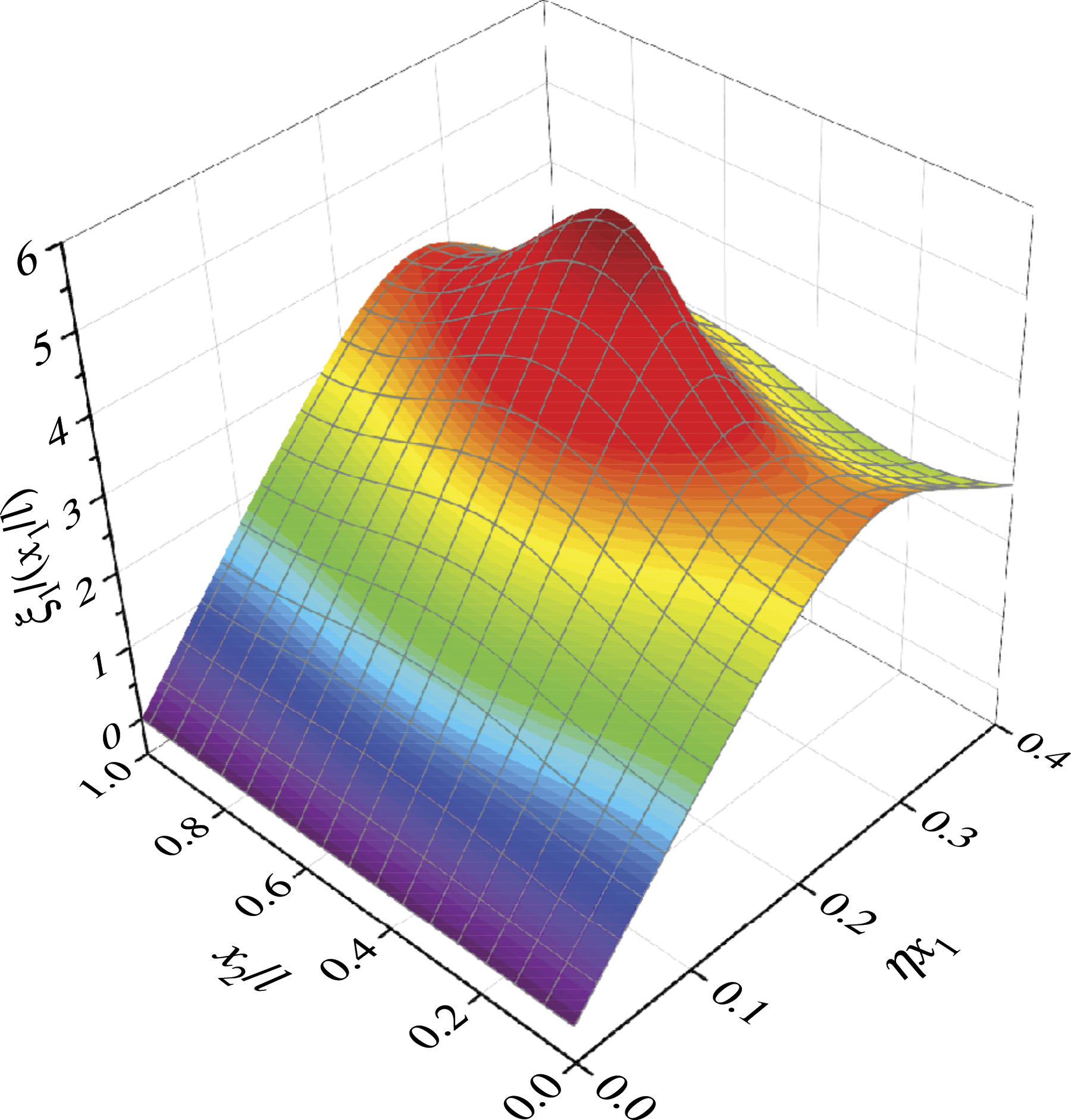
The cross-tie at the cable mid-span
To further analyze the effects of the stiffness coefficients of the cross-tie on the damping and frequency of a cable with a PVMD and a grounded cross-tie, the PVMD and the cross-tie are installed at the positions of x1=2%l and x2=50%l from the left cable end. Figure 10 shows the first modal complex wave numbers of a cable with a PVMD and a grounded cross-tie under various stiffness coefficients of the cross-tie. It is noteworthy that the frequency and the damping ratio of the cable increase significantly with the increase of the stiffness coefficient of the cross-tie. The first modal complex wave numbers of a cable with a PVMD and a grounded cross-tie under various stiffness coefficients of the cross-tie (x1=2%l, x2=50%l, χ=0.9/(nπx1/l)).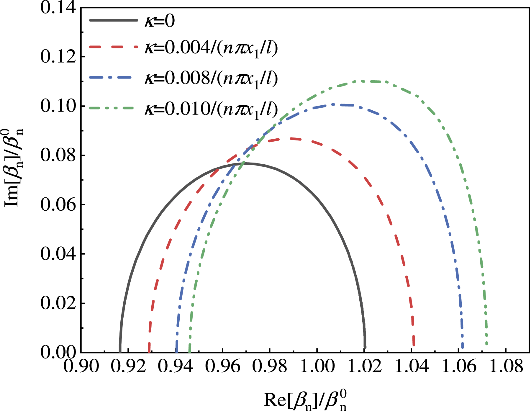
Figure 11 shows the influence of the damping coefficients of PVMD and the stiffness coefficients of the cross-tie on the first supplemental modal damping ratio of the cable. It can be seen from Figure 11 that when the stiffness coefficient of the cross-tie is determined, the first supplemental modal damping ratio of the cable increases with the increase of the damping coefficient of the PVMD, reaching the maximum value at the optimum damping coefficient of the PVMD, and then decreases with the further increase of the optimum damping coefficient of PVMD. Furthermore, the optimum damping coefficient of the PVMD decreases with the increase of the stiffness coefficient of the cross-tie, which helps to reduce the damping cost to achieve optimal vibration control performance of the cable. Variations of the first supplemental modal damping ratio of the cable with the damping coefficients of PVMD and stiffness coefficients of the cross-tie (x1=2%l, x2=50%l, χ=0.9/(nπx1/l)).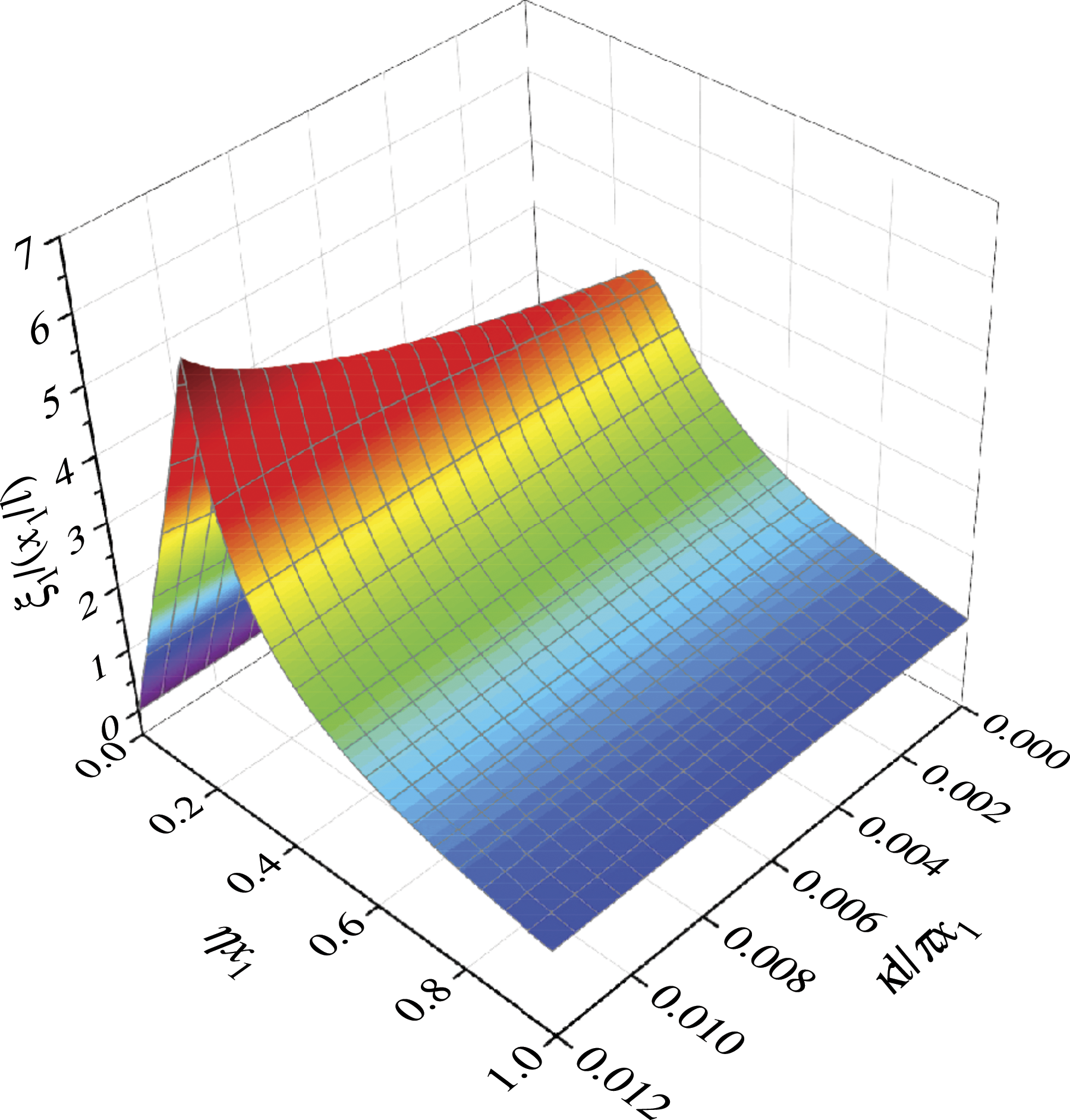
Figure 12 compares the maximum first supplemental modal damping ratio of a cable with a PVMD and a cross-tie, a single PVMD, as well as a VD and a cross-tie. It is found in Figure 12 that when the cross-tie is installed at the cable mid-span, the maximum first supplemental modal damping ratio of a cable with PVMD and cross-tie is greater than that of a cable with VD and cross-tie or single PVMD. In addition, the maximum first supplemental modal damping ratio of the cable increases with the increase of the stiffness coefficient of the cross-tie. The maximum first supplemental modal damping ratio of the cable (x1=1%l, x2=50%l).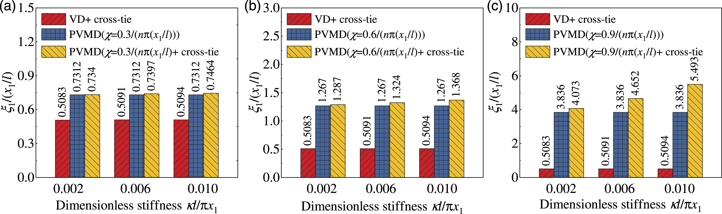
Conclusions
In this paper, the coupled damping effect of a cable with a parallel-connected viscous mass damper (PVMD) and a grounded cross-tie is investigated. The coupled damping effect of a PVMD and a grounded cross-tie on a stay cable is compared with that of a viscous damper (VD) and a grounded cross-tie on a stay cable. Moreover, the effects of the stiffness coefficients and installation positions of the cross-tie on the damping of the cable are emphatically analyzed. The main conclusions are summarized as follows: (1) The supplemental modal damping ratio of a cable with a PVMD and a grounded cross-tie is significantly improved compared with that of a cable with a VD and a grounded cross-tie, which indicates the coupled damping effect of a PVMD and a grounded cross-tie on a stay cable is superior to that of a VD and a grounded cross-tie on a stay cable. (2) When a PVMD and a ground cross-tie are installed at the same cable end, increasing the dimensionless stiffness coefficient of the cross-tie has negative effects on improving the maximum supplemental damping ratio of the cable, and the maximum supplemental modal damping ratio of the cable decreases with the cross-tie moving away from the PVMD. (3) When a PVMD and a ground cross-tie are installed at opposite cable ends, increasing the dimensionless stiffness coefficient of the cross-tie is beneficial to enhance the maximum supplemental damping ratio of the cable, and the maximum supplemental modal damping ratio of the cable increases with the cross-tie moving close to the cable mid-span. (4) The cable mid-span is determined as the optimal installation position of the cross-tie to improve the vibration control performance of the cable for the first mode. When the cross-tie is installed at the cable mid-span, the first supplemental modal damping ratio of the cable reaches the maximum.
Footnotes
Declaration of conflicting interests
The author(s) declared no potential conflicts of interest with respect to the research, authorship, and/or publication of this article.
Funding
The author(s) disclosed receipt of the following financial support for the research, authorship, and/or publication of this article: The National Natural Science Foundation of China (Grant No. 51878274).