
Abstract
A high-precision equipment is very sensitive to vibration, even micro vibration. How to isolate the low-frequency broadband multidirectional vibration remains a challenge. As the main component of piezoelectric smart vibration isolation model, the piezoelectric stack consists of a piezoelectric actuator, a piezoelectric sensor, and a rubber layer. The numerical results obtained by the finite element method agree well with theoretical solutions. The vibration attenuates rapidly under displacement and velocity feedback control with negative gains. As the control gain decreases, the vibration isolation band is extended to lower frequency. A piezoelectric smart multidirectional vibration isolation platform model is further proposed by inclined installation of two piezoelectric stacks. A spring-like structure is designed to exert a preload pressure on these piezoelectric stacks. After optimization on the control gain, the platform can isolate vibration from 0 to 3000 Hz in multiple directions.
Keywords
Introduction
The active smart system is an effective way to control structural vibration, which always consists of piezoelectric sensor and actuator. Vibration isolation performance of the system can be effectively regulated by the voltage of the piezoelectric actuator. Active control with piezoelectric sensor and actuator was proposed many years ago. 1 Extensive research has been conducted for three decades to suppress the vibrations in large space structure, civil structure, helicopter, aircraft, and computer hard disk driver. 2 The voltage relationship between sensor and actuator is determined by piezoelectric active control strategy, which usually plays a decisive role in vibration reduction. Therefore, many scholars have conducted in-depth research. He et al. 3 controlled the vibration of functionally graded material plate by velocity feedback control strategy. Furthermore, many other structures, such as piezoelectric plate and shell,4,5 were studied by this strategy. In addition, Moita et al. 6 applied displacement feedback control strategy to control the vibration of the piezoelectric laminated sheet. The vibration of a flexible beam was controlled by angular velocity feedback strategy. 7 Furthermore, multiple control strategies were usually applied simultaneously. Karagülle et al. 8 studied displacement, velocity, and displacement integral feedback control strategies to control the vibration of cantilever beam by ANSYS. Liew et al. 9 employed both velocity and displacement feedback control strategies to control the vibration of laminated composite plates. Moreover, active vibration control by multiple strategies was also investigated extensively in different types of functionally graded plates.10–12 So far, velocity feedback control and displacement feedback control have become the basic means for active control.
It is also an effective vibration isolation method to adjust the frequency band gap by modifying the stiffness of periodic structures through piezoelectric active control. 13 Li et al. 14 adjusted the stiffness of periodic piezoelectric beam by active control, and isolated vibration propagation successfully. With the same method, the stiffness of periodic piezoelectric beam was modulated to widen its band gap 15,16 Yi et al. 17 designed an appropriate feedback law to control the bending stiffness of the beam, and then achieved tunable band gaps and non-reciprocal wave propagation.
To enhance the effect of active control, some optimizations were studied. In terms of structural optimization, the placement of sensors and actuators was optimized on carbon nanotube reinforced composite plates and flexible cantilever plate.18,19 The topology optimization of flextensional piezoelectric actuators was carried on a cantilever model and a thin shell.20,21 In terms of control strategies, active vibration control as well as an optimal time delay were developed and identified for a cantilever beam. 22
Active control can also be applied in many other aspects, such as acoustic cloaks, 23 optical mirrors, 24 aircraft wing, 25 and thin-walled wing engine system. 26 In recent years, the innovation of active control algorithm27–31 and methods32,33 and the improvement of control system stability have been research hotspots of active control. 34 Moreover, as an actuator, the piezoelectric stack was usually applied in vibration isolation. He et al. 35 suppressed the vibration of the high-speed bearing-rotor system by using piezoelectric stack.
However, effective isolation of vibration input from the ground has always been a difficult issue in precision manufacturing. Nelson 36 proposed an active control structure system by installing piezoelectric sensor as well as piezoelectric stacks under the equipment. Ryan 37 introduced the active control system into a high-precision optical platform, but the control law was not given and the mechanism was also not clear. The team at University of Twente carried out the integrated design on active control system.38–41 Chen and Li 42 designed a monolithic self-sensing precision stage to achieve vibration isolation. However, the underlying mechanism needs to be further explored beyond the experiments. It is necessary to conduct in-depth theoretical research to improve performance of active vibration control. In addition, one of the advantages of active control is the effective control of low-frequency vibration. But controlling vibrations at lower frequencies and wider frequency bands remains a challenge. Multidirectional vibration is a common phenomenon in engineering, and the control of multidirectional vibration is another challenge of active control.
Face to these two challenges, the paper aims to study low-frequency multidirectional vibration isolation. Firstly, the piezoelectric smart model is proposed by introducing the piezoelectric sensor and actuator. Different control laws of the active control are then implemented to adjust the active damping and stiffness. The vibration isolation performance under different control gains is studied in time domain and frequency domain, respectively. Finally, multidirectional vibration isolation platform is proposed to investigate vibration control in two directions.
Piezoelectric smart vibration isolation model and control laws
As shown in Figure 1, the proposed piezoelectric smart vibration isolation model consists of a piezoelectric stack and a high-precision equipment. The piezoelectric stack is composed of a piezoelectric actuator, a piezoelectric sensor, and a rubber layer. The high-precision equipment is simplified as a rigid body due to its large stiffness. As an insulation material, the rubber layer is introduced between the sensor and actuator. The resonance frequency is also reduced because of its low stiffness. As the sensor, a single piezoelectric patch is placed below the rigid body whose polarization direction is along the vertical direction. Upper and lower surfaces of the piezoelectric patch are electroded. The lower electrode is grounded. As the output voltage, potential difference between the upper and lower surfaces can be monitored by the voltage on the upper surface. The actuator is composed of N layers of piezoelectric patches, where N = 18. Half of the layers are polarized along the thickness direction, and the other half are polarized in the opposite direction. In order to produce the synchronous deformation, piezoelectric patches in two different polarization directions are arranged alternately. Piezoelectric smart vibration isolation model. (a) Structure and circuit connection. (b) Geometric dimensions and the boundary conditions.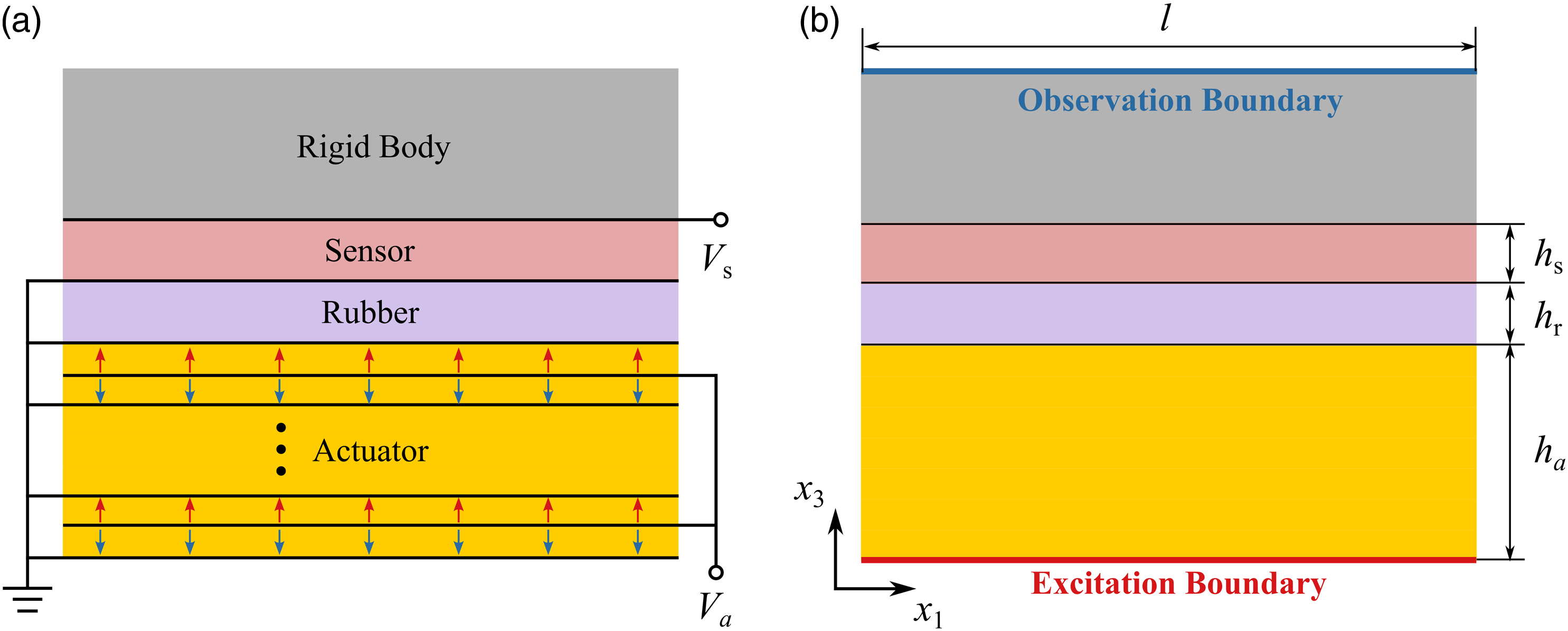
The constitutive equation of piezoelectric materials can be written as
For one-dimensional thickness extension motion of a thin patch, equation (1) can be simplified as

For the piezoelectric sensor, the electric displacement is equal to 0 at the condition of open circuit. Hence, equation (2) becomes


Displacement feedback control and velocity feedback control are basic control strategies.
9
Base on these two control strategies, the relationships between voltages V
s
and V
a
of the sensor and the actuator can be written as


Similarly, the differential relation can be derived by equations (5) and (7).

As we can know, the driving force of the actuator is positively correlated with the actuator voltage V a . Besides, T3 is positively correlated with the acceleration of the rigid body. Thus, the relationship between the displacement of the rigid body and the driving force of the actuator can be regulated by Gd from equation (8). Similarly, the relationship between the velocity of the rigid body and the driving force of the actuator can be regulated by Gv from equation (9). Thus, the magnitude and direction of the actuator output force can be modulated by tuning Gd or Gv, which can be applied to generate damping or to enhance vibration.
In addition, the stiffness of the model and the vibration propagation characteristics can also be adjusted by displacement feedback control. Let the total deformation of the piezoelectric stack be Δx3, and the strain of the piezoelectric stack can be assumed as

By ignoring the inertial force of the rubber, the stress T3 on its upper and lower surfaces is equal. The displacement of the load is set as x3. According to the constitutive relation of the rubber, the stress of the rubber is

Combine equations (5) and (6), the actuator voltage can be written as


Combine equations (3), (10), (11), and (13), the stress of the actuator is

It can be seen from equation (15) that the stiffness can be modulated by controlling the gain Gd. For a positive Gd, the structure is hardened by the piezoelectric effects; while for a negative Gd, the structure is softened. Therefore, it can be further inferred from statics analysis that the stiffness and vibration propagation characteristic of the structure can be adjusted by displacement feedback control.
Piezoelectric smart vibration isolation model with active control
Time domain vibration attenuation analysis
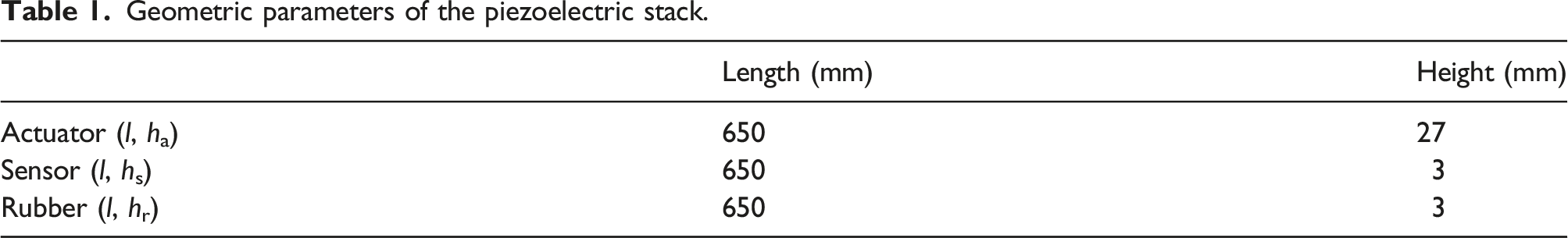
Geometric parameters of the piezoelectric stack.
Material parameters of PZT-5H.
The piezoelectric smart vibration isolation model is calculated by software ANSYS with APDL language. As shown in Figure 1(b), an acceleration excitation along x3-axis acts on the bottom of the model, which is set as excitation boundary (EB). The top surface of the rigid body is set as observation boundary (OB), whose vibration along x3-axis is measured. The presets of structural damping α = β = 1 × 10⁻⁷. The time step is set as 0.05 ms. The acceleration excitation versus time is shown in Figure 2(a), here the excitation lasts 2 ms. The displacement of the observation boundary (OB) versus time without active control is shown in Figure 2(a). The vibration of the rigid body and excitation are synchronous within excitation time. After the excitation, the structure vibrates at a frequency, 840.3 Hz. The frequency is close to the natural frequency, 836.5 Hz, of the first thickness stretch mode, which is also plotted in Figure 2(b). The vibration further decays slowly under the effect of structural damping. Excitation and response versus time in 10 ms. (a) Acceleration excitation and displacement response at observation boundary (OB). (b) Modal shape of the first thickness stretch mode with natural frequency, 836.5 Hz.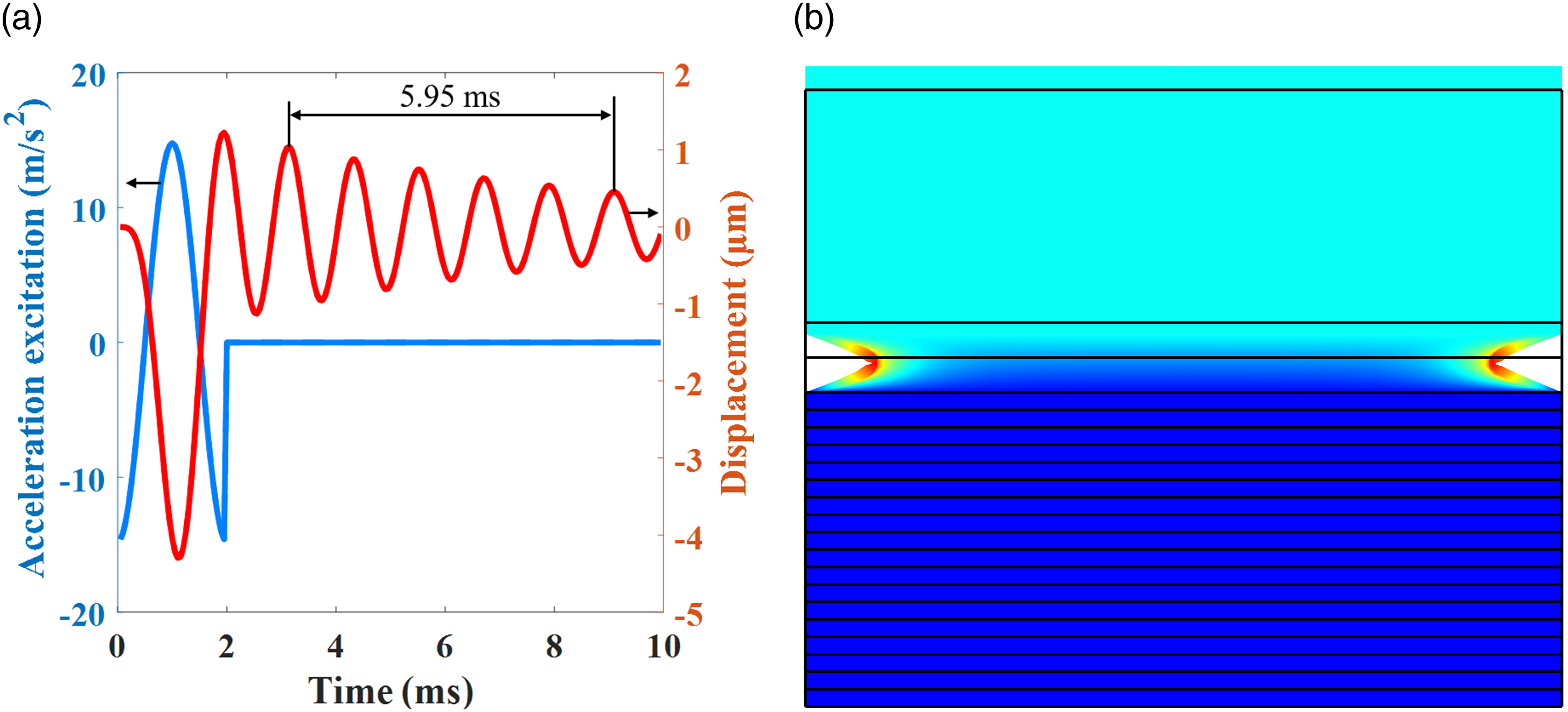
The vibration of the rigid body is further investigated under the displacement and velocity feedback control. Figure 3(a) illustrates that the vibration of the rigid body gradually decreases at a negative Gd, while the vibration increases at a positive gain as shown in Figure 3(b). Similar results are obtained under velocity feedback control as shown in Figure 3(c) and (d). The vibration of the rigid body gradually decreases for the negative Gv but increases for the positive one. For the negative Gv, the force acting on the rigid body by the actuator is opposite to the velocity direction; thus, vibration attenuates rapidly. However, for the positive Gv, the situation is reversed. Displacement time history of OB at different feedback control gains. (a) Gd = −100, (b) Gd = 50, (c) Gv = −0.004, and (d) Gv = 0.004.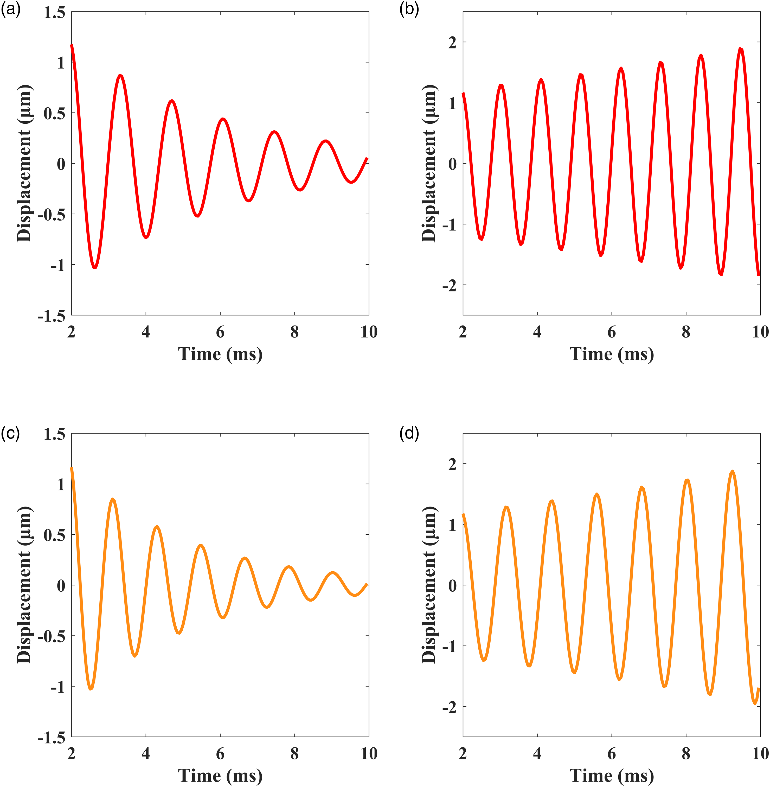

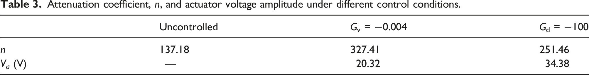
Attenuation coefficient, n, and actuator voltage amplitude under different control conditions.
Since the output force of velocity feedback control has the same property as the damping force, it is obvious that velocity feedback control has good damping effect. However, displacement feedback control cannot form effective damping, and furthermore its damping mechanism is still not clear. Therefore, it is necessary to analyze the relationship between actuator voltage and load displacement. Figure 4(a) and (b) show actuator voltage and velocity of rigid body versus time under velocity feedback control and displacement feedback control, respectively. A certain time lag between the sensor and the actuator is equal to the time step, where 0.05 ms is selected in calculation. However, in displacement feedback control, the voltage and displacement of displacement feedback control are not completely synchronized because of the hysteresis between the actuator and the sensor. But piezoelectric damping can still be formed in the driving force of the actuator during the hysteresis period, which results in vibration attenuation. Actuator voltage and velocity of rigid body versus time at different control gains. (a) Gv = −0.004. (b) Gd = −100.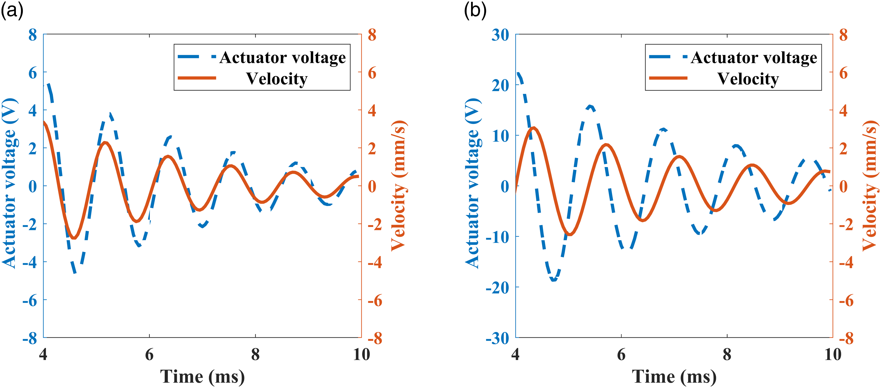
Figure 5 shows the displacement time history of the rigid body within 30 ms when Gv = −0.004. It can be noted that the vibration of the structure is attenuated to an equilibrium position after 20 ms. Under the continuous action of active control, the structure remains in this equilibrium position. If the structure is excited by vibration again, the amplitude of the sensor voltage generated by deformation will be greater, and according to the control strategy, the amplitude of the actuator voltage will also be recovered. No manual intervention is required, and the vibration suppression performance remains as effective as before. Displacement time history of OB over a long period of time when Gv = −0.004.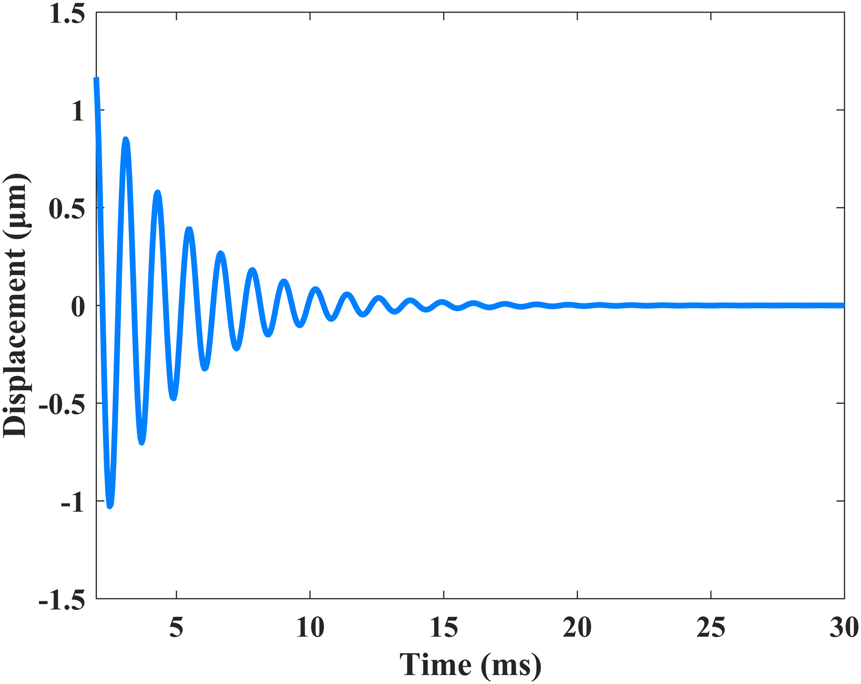
Frequency domain vibration isolation analysis
One-dimensional laminate theoretical model is proposed by taking the vertical vibration of piezoelectric damping structure into consideration. The frequency response of the structure is calculated by transfer matrix method (TMM). The thickness of each layer of the actuator is set as 2hp and the density is ρp. The thickness of elastic rubber layer is set as hr = 2he, and the thickness of piezoelectric sensor as hs = 4hp. hp = 0.75 mm, he = 1.5 mm, and total layer number of the actuator N = 18 are fixed in the calculation.
Only considering the vibration in the thickness direction, the displacement u3 and potential φ of the piezoelectric layer can be written as

Submitting into equation (2) yields
The equation of motion and the charge equation require that
Equations (19) and (20) yield


By substituting equation (22) into equation (21), the equation of motion can be simplified as
The general solution of displacement and voltage can be obtained as

For the piezoelectric sensor, current and electric displacement are 0 because of its open circuit condition. So the displacement, potential, and stress of the sensor can be simplified as
For the elastic rubber layer, the constitutive equation and equilibrium equation are


Its general solution is
According to equation (28), we get

According to equation (6), the actuator voltage is
According to equation (26), the electric potential of the actuator is
The electric potentials of the upper and lower surfaces of the odd-layer actuator are
Combining equations (36) and (37), B1a can be expressed as

After determining B1a and V a , only two coefficients are undetermined for each layer, A1s and A2s for sensing layer, A1a and A2a for actuator layer, and C1 and C2 for the rubber layer. These undetermined coefficients of the structure can be derived by the transfer matrix method.
At the interface between the rubber and the sensor, the continuity conditions of stress and displacement are
Then the transfer matrix between the rubber and the sensor can be written as follows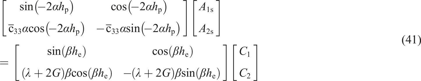
Similarly, the continuity conditions at the interface between the rubber layer and the actuator are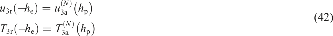
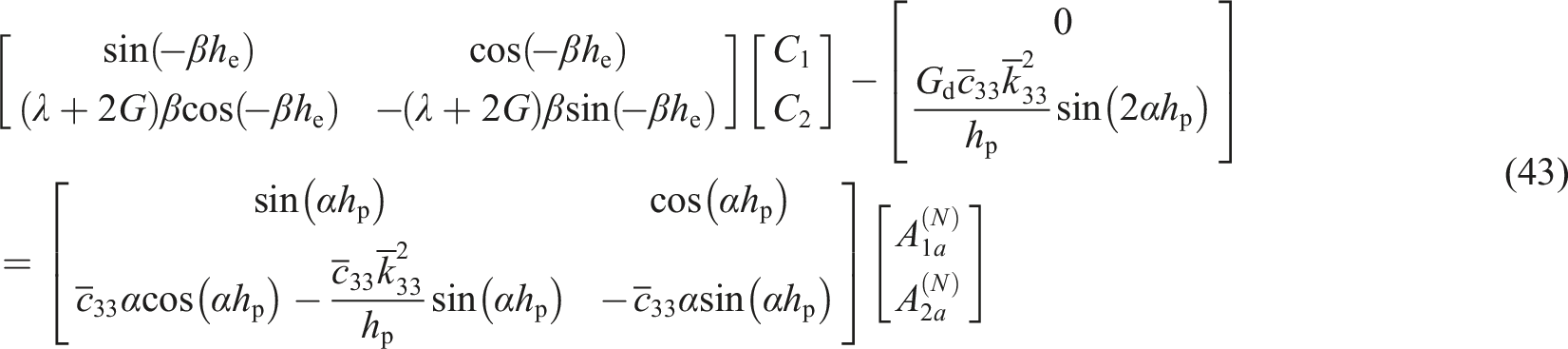
The continuity conditions at the interface between n-1 and n layer of the actuator are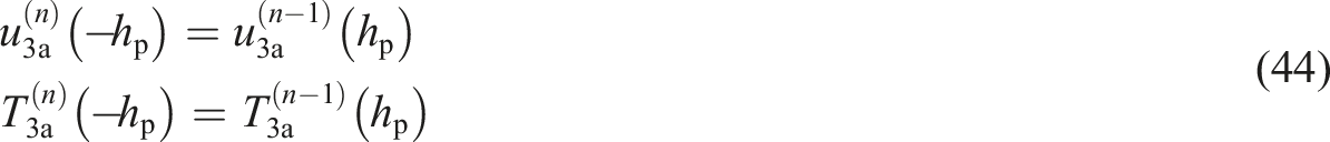
For the rigid body, the equilibrium condition satisfies

The frequency response relation of the structure can be written as
The effect of active control on vibration isolation is calculated by the finite element method (FEM) on software COMSOL Multiphysics. As illustrated in Figure 1, the bottom is excited by the vibration with displacement amplitude, Uin, along the x3 axis. The output displacement amplitude, Uout, along the x3 axis at the top of the model is then measured. Damping is introduced using complex elastic constants. c33 is replaced by c33 (1 + iQ−1) in the theoretical calculation. For ceramics, Q is of the order of 100–1000. Q = 100 is used.44,45
In order to verify these methods, harmonic response analyses on the model in Figure 1 are made by theoretical calculation and FEM. Figure 6(a) shows the frequency response curve obtained by TMM as theoretical calculation, and FEM as numerical calculation, where Gd = −1000 is fixed. Figure 6(b) shows the characteristic frequency versus control gain calculated by these two methods. The results agree well with each other, which verify the accuracy of the two calculation methods. Figure 7 shows the vibration displacement amplitude nephograms at 200 Hz without active control and with active control, where the control gain Gd = −2 × 10⁴. It can be seen from Figure 7(a) that the vibration amplitude of the rigid body is greater than that of the bottom. Hence, the vibration is enhanced when without active control. On the contrary, with active control, the vibration amplitude is weakened layer by layer along the piezoelectric actuator, as shown in Figure 7(b). Comparison of calculation results obtained from theoretical solution (TMM) and finite element calculation (FEM). (a) Frequency response curves when Gd = −1000. (b) The characteristic frequency versus control gain. Displacement distribution of the piezoelectric smart vibration isolation model under excitation of 200 Hz. (a) Without active control. (b)With active control and the control gain Gd = −2 × 10⁴.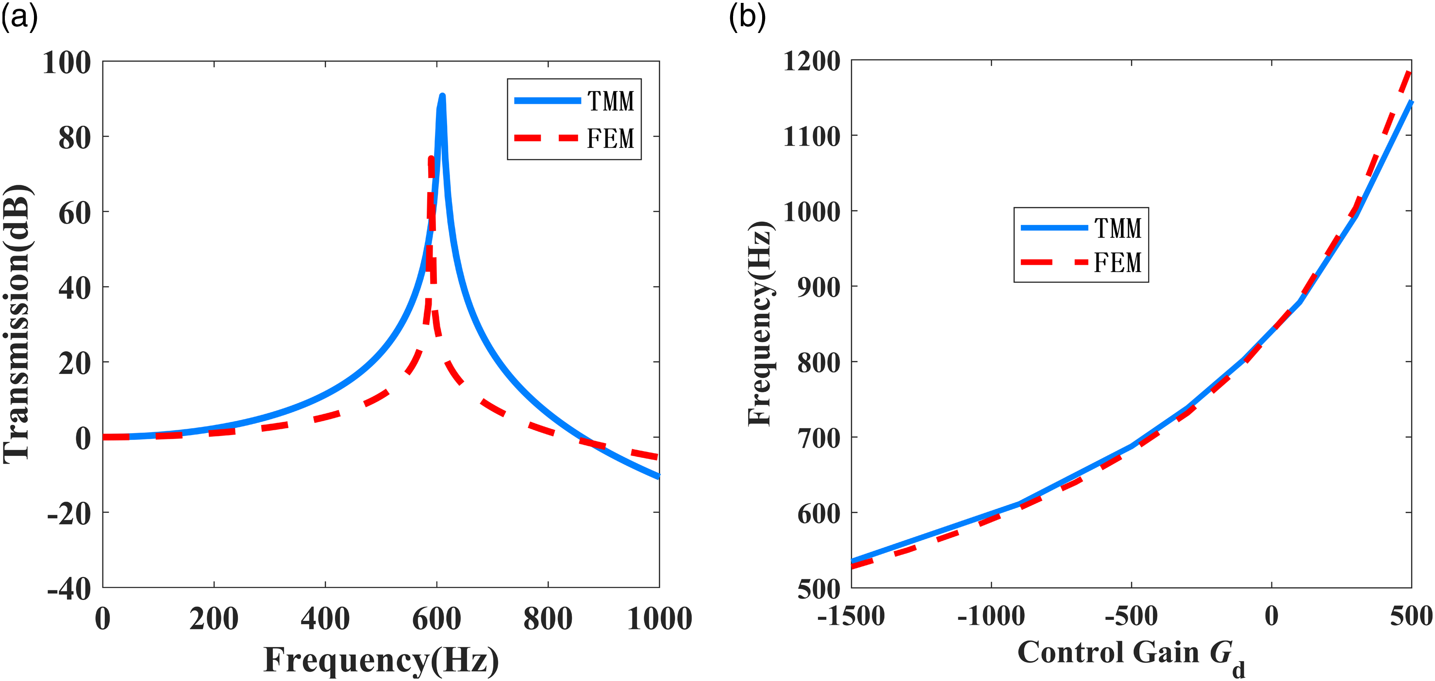
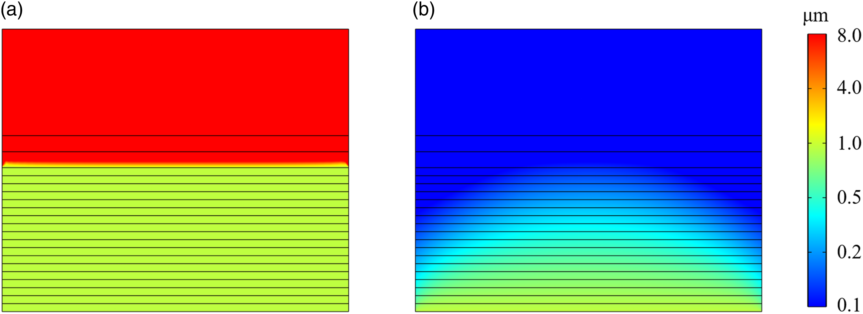
Figure 8 shows the frequency response curves of the model under different displacement feedback control gains. It is worth noting that the model is softened by the negative Gd. It leads to a decrease of the natural frequency of stretch mode. Comparing to the free vibration without control, the frequency response curve shifts to the low-frequency band. As Gd decreases, the vibration isolation band is extended to lower frequency. On the contrary, the model is hardened by the positive Gd. The frequency corresponding to the peak increases with the increase of the gain, as shown in Figure 8(b). Therefore, from Figures 3 and 7, each control strategy is less sensitive to parameter errors but is more sensitive to the positive and negative signs of their gain coefficients. Frequency response curves of the displacement at different control gains. (a) Gd < 0; (b) Gd > 0.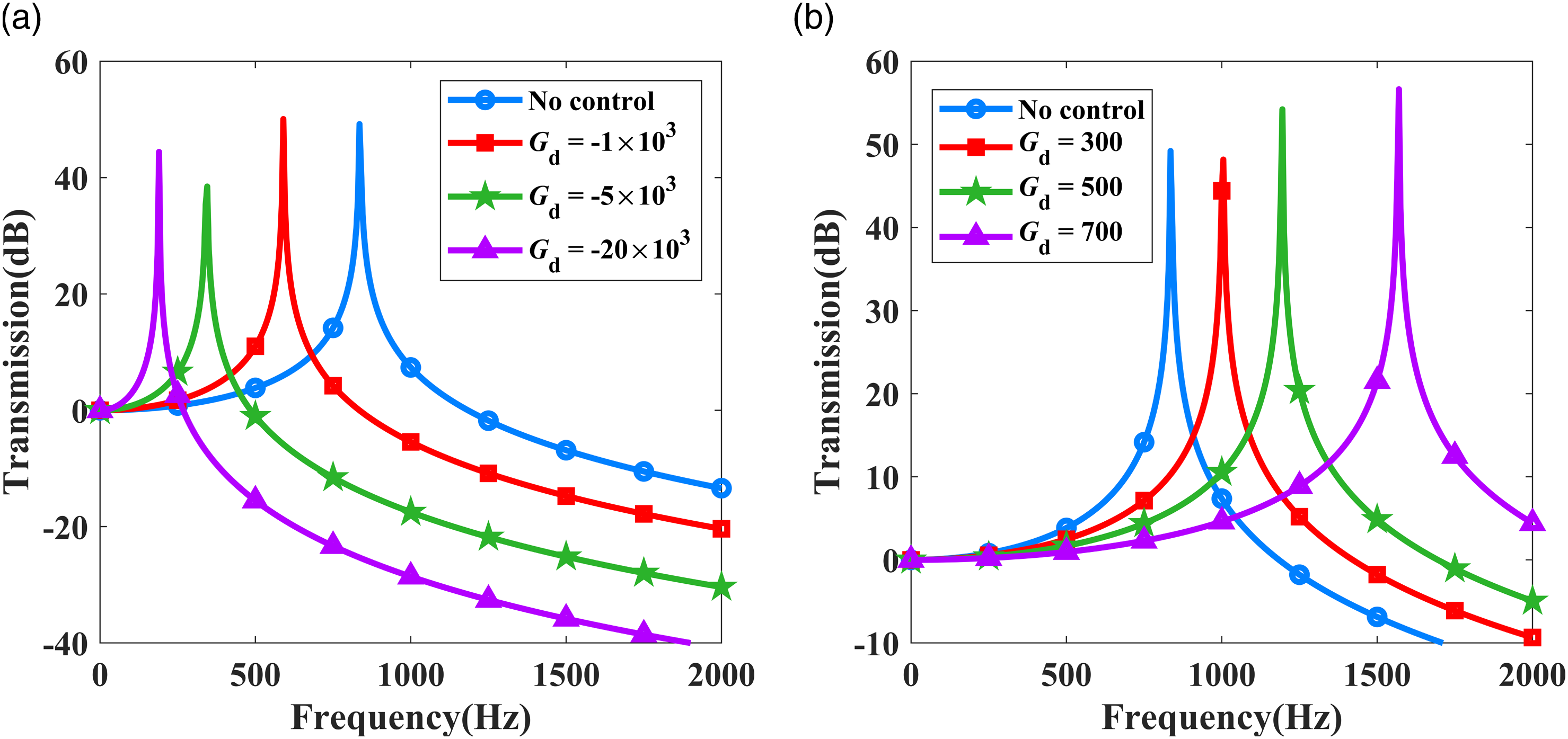
Multidirectional vibration isolation platform
The tensile strength of piezoelectric ceramics is usually poor due to their easy fracture under tensile stress. When the control gain is large, the structure may become unsafe. To avoid the problem, a pressure is usually preloaded on the piezoelectric stack. Holterman
39
designed a piezoelectric vibration isolation platform by considering the strength of a piezoelectric actuator. Based on the idea, a piezoelectric smart multidirectional vibration isolation platform model is designed. As a symmetric structure, only the main view is displayed in Figure 9, where l0 = 80 mm, h0 = 30 mm, and the width of each gap is 0.5 mm. The model consists of a support platform and two piezoelectric stacks. Two cavities are reserved in the platform for mounting two piezoelectric stacks. The platform is carved with multiple gaps to form a spring-like structure. A preload pressure is exerted on the piezoelectric stacks by the spring-like structure. In addition, due to the inclined installation of the piezoelectric stacks, the movement of the platform in the horizontal and vertical directions can be controlled at the same time, and multidirectional vibration isolation is then achieved. Piezoelectric smart multidirectional vibration isolation platform.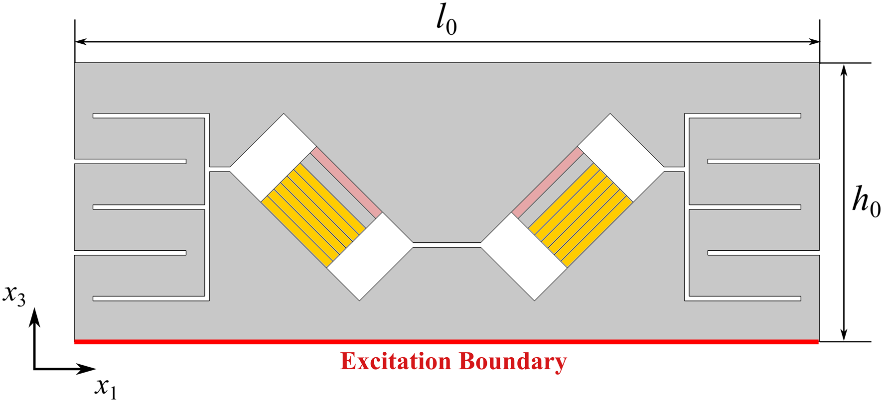
The piezoelectric stack is adopted with similar structure as shown in Figure 1. The only difference is that the rubber is replaced by aluminum. The length l = 10 mm, the thickness of each piezoelectric layer is 1 mm, and the thickness of the aluminum layer is 1.5 mm. The piezoelectric material in the platform is still PZT-5H. For the aluminum layer, the density is 2700 kg/m3, the Young’s modulus is 79 GPa, and the Poisson’s ratio is 0.33.
Assuming a rigid body, a precision equipment with a mass of 24 kg is placed on a vibration isolation platform to evaluate its multidirectional vibration isolation performance. Displacement excitations in the horizontal and vertical directions are applied to the excitation boundary (EB) of the vibration isolation platform. The response of the rigid body in the horizontal and vertical directions is then measured. The harmonic response analysis of the model is operated by software COMSOL.
In order to display the multidirectional vibration isolation performance of the vibration isolation platform, Figure 10(a) and (b) are plotted to show the displacements of the platform along x1 and x3 axis at 1000 Hz without active control. The displacement of the OB is greater than that of the EB in either x1 or x3 direction. Therefore, vibration at 1000 Hz is not isolated by the platform without control. However, Figure 10(c) and (d) illustrate the vibration amplitudes of the OB in two directions are both smaller than those of the EB, where Gd = −100. Hence, the vibration is weakened by the platform with active control. The platform has excellent vibration isolation performance even when the vibration along x1 and x3 axis excites at the same time. Displacement of piezoelectric vibration isolation platform at 1000 Hz. (a) and (b) Without active control, displacements along x1 axis and x3 axis, respectively. (c) and (d) Active control with Gd = −100, displacements along x1 axis and x3 axis, respectively.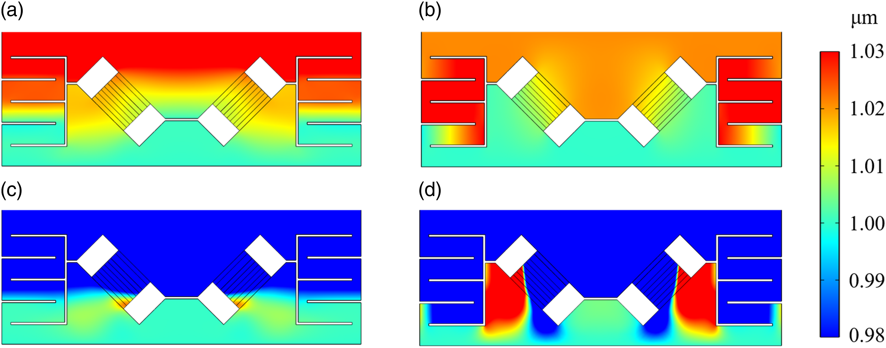
Figure 11 further demonstrates frequency response curves of the vibration along x1 and x3 axis, respectively. With the reduction of Gd, the frequency corresponding to the peak of the curve decreases, so the vibration isolation frequency band moves to the lower frequency. It is worth pointing out that when Gd = −30, vibration along x1 axis is isolated in the range of 0–3000 Hz, but the vibration along x3 axis is amplified. Nevertheless, when Gd = −100, the isolation vibration along both x1 and x3 axes can be achieved in the same frequency range. Accordingly, the piezoelectric vibration isolation platform can isolate the low-frequency and broadband vibration in two directions by tuning the control gain Gd. Frequency response curves of the piezoelectric vibration isolation platform. (a) Along x1 axis. (b) Along x3 axis.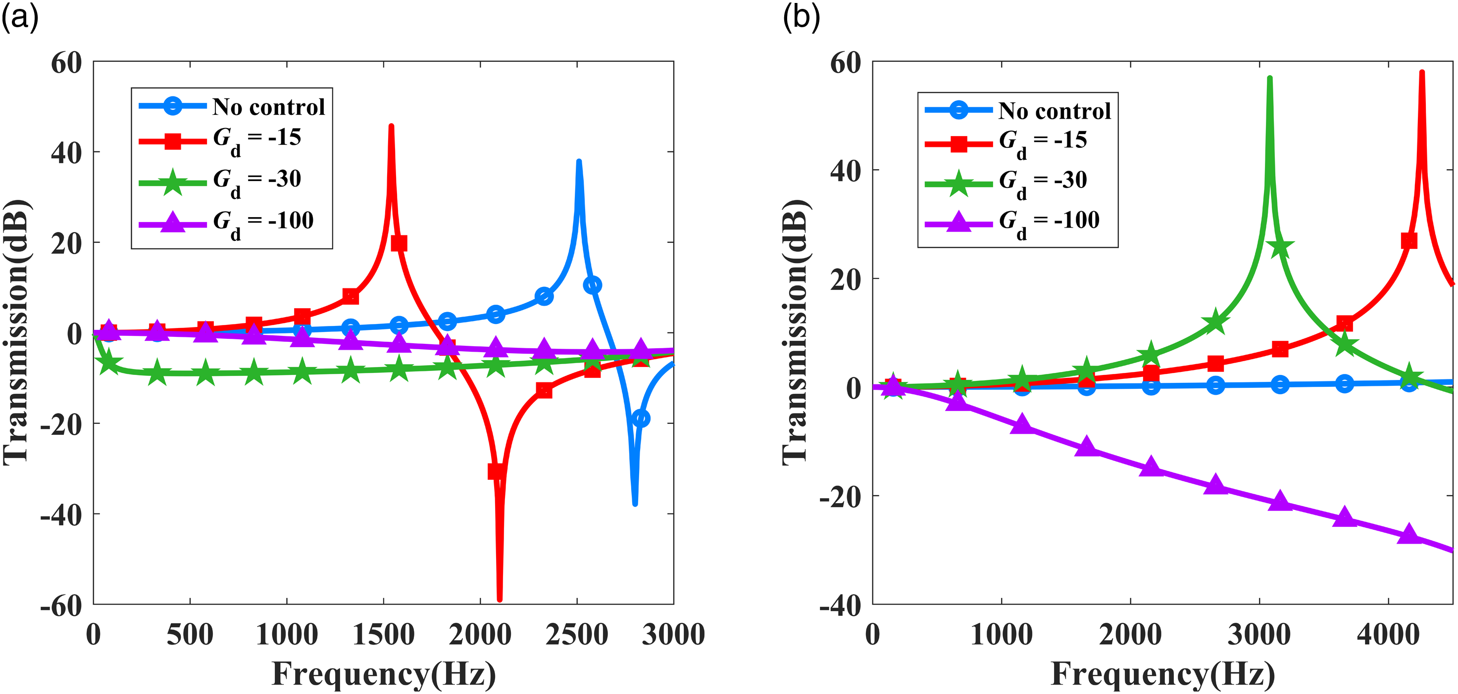
Conclusions
The piezoelectric smart vibration isolation platform model with thickness of 30 mm was proposed, which can isolate low-frequency broadband multidirectional vibration. Dependence of vibration isolation performance upon control gain is studied based on displacement and velocity feedback control strategies of piezoelectric active control. Some conclusions are drawn as follows. 1. The vibration transmission can be adjusted by velocity and displacement feedback control strategies. A negative control gain weakens the vibration, while a positive control gain has opposite effect. 2. The stiffness of the structure can be modulated by displacement feedback control strategy. A negative control gain softens the structure. Hence, the lower frequency vibration can be isolated effectively. 3. The control gain of the vibration isolation platform has been optimized to isolate low-frequency and broadband vibration in multiple directions.
Footnotes
Acknowledgments
The computation is completed in the HPC Platform of Huazhong University of Science and Technology.
Declaration of conflicting interests
The author(s) declared no potential conflicts of interest with respect to the research, authorship, and/or publication of this article.
Funding
The authors gratefully acknowledge the financial support of the National Natural Science Foundation of China (NSFC) (11872186, 12232007, and 11972164), and Fundamental Research Funds for the Central Universities (HUST: 2016JCTD114).