
Abstract
Piezoelectric stack actuators are a type of excellent smart devices that can activate large power and displacement outputs due to their unique stack configuration and have been widely used in linear vibrators for various engineering applications. For the fabricated piezoelectric stack actuator, it usually consists of multiple thin piezoelectric wafers, multiple electrodes, and two protective layers. All the piezoelectric wafers are connected electrically in parallel through the electrodes and are protected by two protective layers at the two ends. However, in most of the theoretical models, the active piezoelectric portion is mainly considered, while the electrodes and protective layers are usually neglected to simplify the complicated problem, which results in an inaccurate prediction of the electromechanical characteristics. In our previously published work, the exact theoretical models of the piezoelectric stack energy harvester and sensor with the electrodes and the protective layers included have been established successfully to evaluate the electromechanical performance of these two types of devices, and their validity has verified by the experimental results. However, the exact theoretical model of the piezoelectric stack actuators has not been established, and the effects of the electrodes and the protective layers on the electromechanical characteristics of the actuator are not fully understood. In this article, the exact theoretical model of piezoelectric stack actuator was derived based on our previous work, and the effects of these two factors on the electromechanical characteristics were investigated. Comparisons with the results in the earlier literatures and the experimental results were presented to validate the model. Furthermore, two kinds of typical working states, including clamped–free (C-F) and free–free (F-F), were discussed. The results showed that neglecting the electrodes and the protective layers will greatly affect the accuracy of the prediction model, thus providing some valuable guidelines in designing the piezoelectric stack actuators.
Keywords
Introduction
Piezoelectric stack actuators, by virtue of their unique stack configuration that can activate large power and displacement outputs, have been widely used in linear vibrators for various engineering applications, such as ultrasonic transducers, 1 –5 higher resolution positioners, 6 fuel injectors, 7,8 self-moving cell linear motors, 9 and so on. This type of actuators is usually fabricated by stacking multiple thin piezoelectric wafers, multiple electrodes, and two protective layers at the two ends. 10 –18 For example, in the work of Yao et al., 12 the fabricated small and hollow piezoelectric stack actuators included 9 PZT ceramic rings, 11 copper shims, and 2 copper caps. In the work of Wang et al., 10,17 the fabricated piezoelectric stack transducers consisted of 20 PZT-5H layers, 21 H62-Brass electrodes, and 2 common ceramic layers. In the work of Tran et al., 13,14 the fabricated piezoelectric stack actuators composed of 40 PMN-29PT layers, 41 thin copper foils, and 2 glass/epoxy caps. In the work of Xu et al. 15 and Qian et al., 16 the adopted piezoelectric stacks produced by CeramTec in Germany composed of 300 layers of Navy Type II (CeramTec SP505) PZT plates, 301 layers of pure silver internal electrodes, and 2 passive layers with no electrodes. In these studies, the thicknesses of the electrodes are 0.1 µm, 15,16 25 µm, 12 60 µm, 13,14 and 0.1 mm, 10,17 respectively. The thicknesses of the protective layers are 1 mm, 15,16 1.48 mm, 10,17 and 2 mm, 11 respectively. All these data demonstrate that the influence of the electrodes and the protective layers cannot be neglected and thus should also be considered in the theoretical modeling in terms of the electromechanical characteristics of the stack actuator.
In recent years, in order to accurately predict the electromechanical behaviors of the piezoelectric stack actuator and guide its design and fabrication, researchers have proposed several improved models to analyze the vibration characteristics. Zhang et al. 19 proposed a three-port equivalent model that separates the piezoelectric stack into one electrical port and two acoustic ports through a transformer. This model broke through the limitations of the existing circuit models, including the earlier and extended Van Dyke equivalent circuit models and other ones 20 –23 that need to use various types of system identification methods to determine the electrical parameters based on the measured information, and can be extended to any mechanical and electrical conditions. Zhang et al. 24 proposed a simplified transfer matrix method of the piezoelectric stack that adopted an equivalent homogenous bulk to consider the whole multilayer structure. This method not only improved the previous transfer matrix method presented in the work of Bloomfield 25 and Morita et al. 26 that considered the transfer matrix of each individual layer and then multiplied them, but also greatly facilitated the direct calculations or the derivation of analytical solutions when the piezoelectric stack was stacked with other structures. Zhang et al. 27 proposed a simple distributed parameter model to study the vibration characteristics of piezoelectric stack actuator-based applications. Compared with the previous equivalent circuit models 20 –23 and transfer matrix methods, 25,26,28 this model was easy to handle using a small number of easily accessible parameters, but extended with the little compromised accuracy. Tran et al. 14 proposed an analytical multi-degree-of-freedom model to predict the resonant frequency, which is validated by the finite element results and the measured ones. Liu et al. 29 established an exact analytical model based on the linear piezo-elasticity theory in hope of assessing the output properties and the inner electromechanical components comprehensively. All these theoretical models played key roles in design, fabrication, and optimization of the piezoelectric stack actuators and promoted their rapid development.
In the theoretical models mentioned above, the electrodes 19,24,27,29 or their masses 14 are usually neglected to simplify the complicated problem; however, they really exist in the actuator. The previous studies have also proved that the electrodes have great effects on the electromechanical behaviors of various piezoelectric devices, including piezoelectric stack energy harvesters and sensors, 10 piezoelectric beams, 30 –33 cement-based piezoelectric composites, 34 –37 and cylindrical piezoelectric transducers. 38 –41 These studies assumed the electrodes as the common elastic layers to reveal some helpful findings for further design and performance optimization, providing good references for the piezoelectric stack actuators. In addition, the protective layers of the actuator are rarely considered in the previous theoretical models, which are the important components in the actuators. It should be pointed out that neglecting their effects can greatly simplify the modeling of the dynamic behaviors of the actuator when their thickness is relative smaller than that of the active piezoelectric portion. However, when their thickness is thick and is comparable to the piezoelectric portion, the predicted electromechanical characteristics are not accurate. 1 For such cases, the effects of the electrodes and the protective layers should be considered. In our previously published work, 10 the exact theoretical models of the piezoelectric stack energy harvester and sensor with the electrodes and the protective layers considered have been established successfully to evaluate the electromechanical performance of these two types of devices, and their validity has verified by the experimental results. However, the exact theoretical model of piezoelectric stack actuator has not been established, and the effects of these two important components on the electromechanical characteristics are not clear. To this end, this article will give the exact theoretical model of piezoelectric stack actuators based on our previous work to study the effects of these two factors on the electromechanical characteristics of the piezoelectric stack actuator. The aim is to give some valuable guidelines in designing the piezoelectric stack actuators.
The remaining contents are organized as follows. The second section gives the theoretical solution of the stack actuator model based on the results from our previous work. The results obtained from the present model with the results in the earlier literature and the experimental results to validate the present model are compared in the third section. The fourth section describes the numerical analysis to study the effects of the thickness of electrodes, the thickness of the protective layer, and the electrode types on the electromechanical characteristics of the actuator. The fifth section concludes the main findings.
Theoretical solution
Figure 1 presents the schematic diagram of the piezoelectric stack actuator. The actuator consists of N piezoelectric layers, N + 1 electrode layers, and two protective layers. Symbols P, E, and C denote the piezoelectric layer, the electrode layer, and the protective layer, respectively. Symbol tP
denotes the thickness of the piezoelectric layer, which is also expressed as
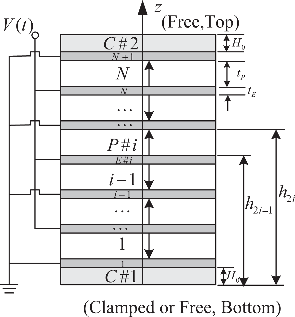
Schematic diagram of the piezoelectric stack actuator.
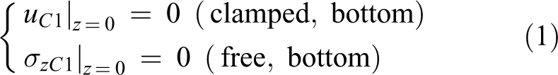
Here, two kinds of typical working states including clamped–free (C-F) and free–free (F-F) are considered. Their mechanical boundary conditions at the bottom and top of the actuator can be written as follows

Based on our previous work.
10
the coefficients


where
The expressions of other coefficients such as

where
The electrical admittance Y can be expressed as

where
When
Comparisons
In this section, comparisons with the results in the earlier literatures and the experimental results are performed to validate correctness of the proposed model.
Comparisons with the results in the earlier literatures
Firstly, comparisons on the free-end displacement for C-F state are given. Zhang et al. 19,27 established a simple distributed parameter model and an equivalent circuit model to study the vibration characteristics of piezoelectric stack actuators, and these models were validated by three-dimensional (3-D) finite element analysis (FEA) model based on ANSYS R15.0 software. In their investigations, piezoelectric material N10 was adopted, whose material properties are listed in Table 1. Two kinds of stacks were considered. One includes 20 piezoelectric layers, 27 and the other includes 10 piezoelectric layers. 19 The detailed geometric dimensions are also listed in Table 1. The theoretical and simulated frequency responses of free-end displacement under 100 V excitation voltage are plotted in Figure 2. The frequency range is from 0 Hz to 200 kHz with a solution interval of 1000 points. Taking the electrode thickness and thickness of the protective layer as negligible values tE = 10−12 m and H 0 = 10−12 m in the present model, it can approximately obtain the results of the above models. In the calculation, H62-Brass electrode listed in Table 2 and the passive layer listed in Table 1 are adopted. In addition, the results of an exact analytical model without electrodes and protective layers developed in our previous work 29 are also addressed in Figure 2. From Figure 2, it can be found that the all the results agree very well in the lower order modes; however, in the higher order modes, the 3-D FEA model, the exact analytical model, and the present approximate model are in good agreement with each other, which are different from the simple distributed parameter model and the equivalent circuit model. The reason for such discrepancy is that in the simple distributed parameter model and the equivalent circuit model, the displacement of each piezoelectric layer is assumed as the uniform distribution across each layer. 19,27
Material properties of piezoelectric layers in piezoelectric stacks.a
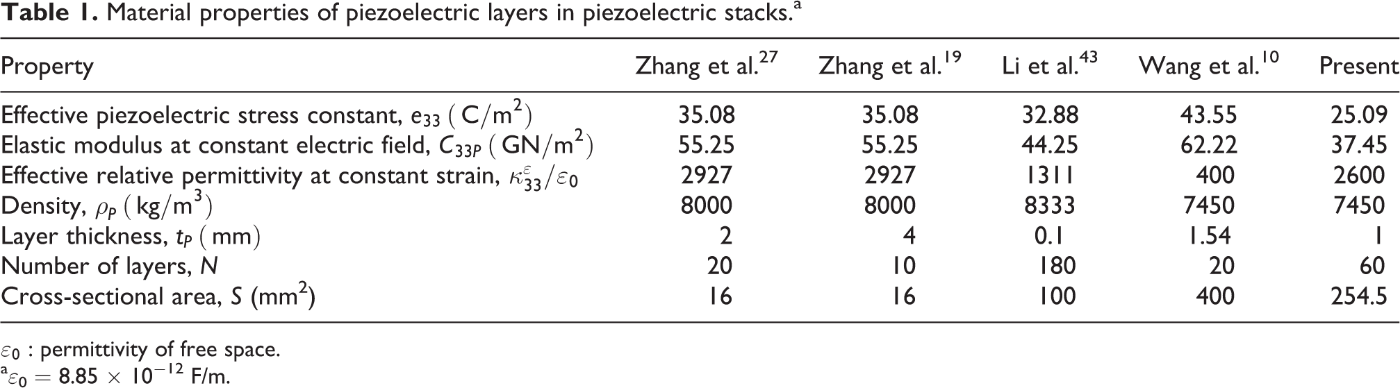
aε0 = 8.85 × 10⁻¹² F/m.

Secondly, comparisons on the resonance and antiresonance frequencies for F-F state are given. Li et al. 43 proposed a refined resonance method to measure the properties of piezoelectric stack under prestress. The piezoelectric stack (PSt 150/20) was employed in the test, whose material properties are listed in Table 1. The F-F state is a special case when the prestress is equal to zero, whose results can be employed to verify the present model. Similar to the above analysis, taking the electrode thickness and thickness of the protective layer as negligible values tE = 10−12 m and H 0 = 10−12 m, the present model can approximately solve the theoretical results of the piezoelectric stack. The experimental resonance and antiresonance frequencies as well as the theoretical ones obtained from the present model are compared and are listed in Table 3. It shows that the experimental results are in good agreement with the theoretical predictions. The above two comparisons validate the correctness of the proposed theoretical model based on our previous work. 10
Here, it should be noted that the material parameters of piezoelectric materials adopted in Table 1 including
Comparisons with the experimental results
In the experiment, nine samples are fabricated, as shown in Figure 3. Each stack includes 60 PZT-5H layers, 61 phosphorous bronze electrodes, and 2 common ceramic layers. The geometric dimensions and material properties are listed in Tables 1 and 2. Each sample is placed on the foam, which can obtain approximately the F-F state. Figure 4 shows the experimental setup. All the impedance–frequency curves can be measured using an impedance analyzer (model: Agilent 4294A), which are plotted in Figure 5. From these curves, the fundamental fr and fa can be obtained, which are further addressed in Table 4 for comparisons. It can be found that the theoretical values are basically in agreement with the experimental ones. The average error is less than 10%, validating the reliability of the theoretical model.

The fabricated piezoelectric stacks.
Material properties of electrodes and protective layers in piezoelectric stacks.


The experimental setup.

The measured impedance–frequency curves.
Comparisons of the fundamental fr and fa for F-F state.

F-F: free–free.
Comparisons of the fundamental fr and fa between theory and experiment for F-F state.a

F-F: free–free.
a Error = (Experiment − Theory)/Experiment
Numerical analysis
In this section, the piezoelectric stack reported in our previous work 10 is adopted to perform the numerical analysis. The piezoelectric layer, the electrode layer, and the protective layer adopted as PZT-5H, H62-Brass, and common ceramic, respectively. Their detailed material properties are listed in Tables 1 and 2. In the following analysis, when one parameter is discussed, other parameters are kept unchanged.
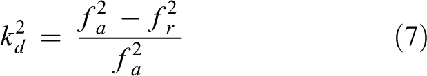
Figure 6 presents the effects of the electrode thickness on the fundamental fr , fa , and kd for both C-F and F-F states. It can be seen that all the fundamental fr , fa , and kd are decreased as the electrode thickness increases. The reason may be explained as follows. The increase in the electrode thickness will induce the decrease of the stiffness and the increase of the mass in each electrode layer. Because the order of magnitude of stiffness is larger than that of mass, the whole stiffness of the actuator presents a decreasing trend. When the change in mass is relative small, a smaller stiffness corresponds to the smaller resonance frequencies.
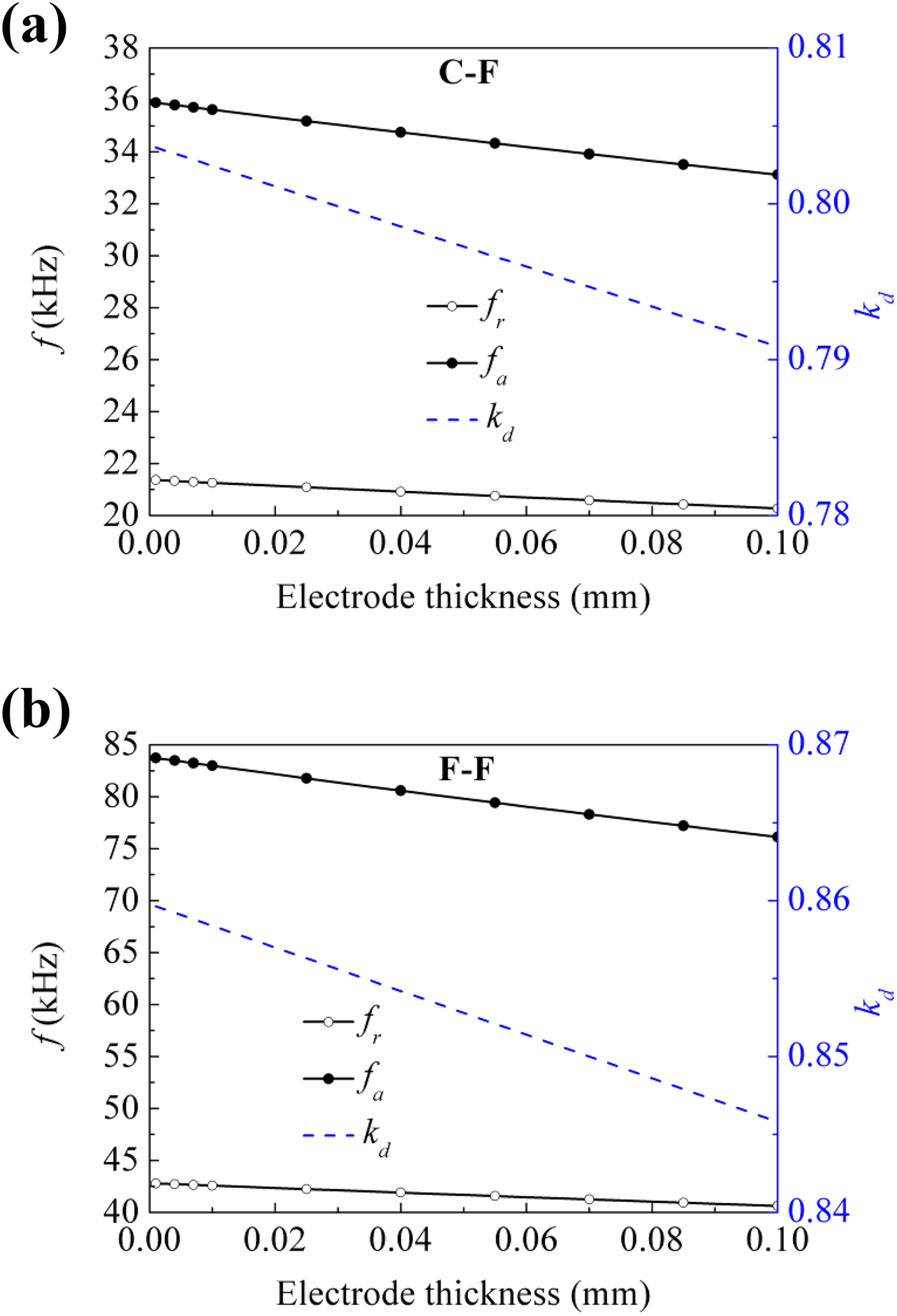
Effects of electrode thickness on fundamental fr , fa , and kd : (a) C-F state and (b) F-F state. C-F: clamped–free; F-F: free–free.
Figure 7 shows the effects of the thickness of the protective layer on the fundamental fr , fa , and kd for both C-F and F-F states. It can be found that for both states, the fundamental fr and fa are decreased as the thickness of the protective layer increases. The physical reason is similar to that of the electrode. However, the fundamental kd has a reverse rule. For the C-F state, it is decreased, while it is increased for the F-F state.

Effects of thickness of protective layer on fundamental fr , fa , and kd : (a) C-F state and (b) F-F state. C-F: clamped–free; F-F: free–free.
Based on the results of Figures 6 and 7, Table 6 lists the comparisons of fundamental fr and fa for piezoelectric stack actuators with/without electrodes and protective layers. From Table 5, it can be found that neglecting the electrodes or the protective layers or both in the actuator model will result in the inaccurate prediction. In this example, a thicker electrode (0.1 mm) is considered; the maximum differences are 9.17, 13.82, and 21.54% for three simplifications, respectively. Therefore, it is necessary to account for these two factors when modeling the actuator to guide the design and fabrication of the piezoelectric stack actuators accurately.

Ni: nickel; Al: aluminum; Cu: copper; Ag: silver; Pt: platinum.
Difference analysis of piezoelectric stack actuators with/without electrodes and protective layers.a
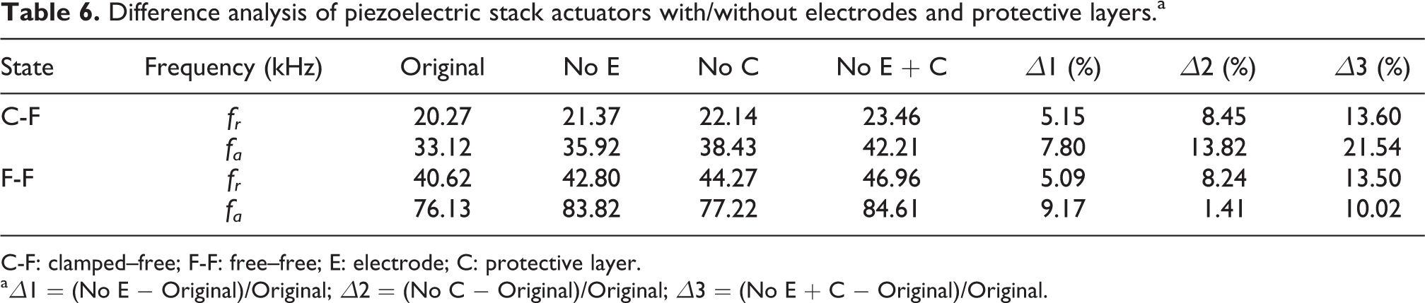
C-F: clamped–free; F-F: free–free; E: electrode; C: protective layer.
aΔ1 = (No E − Original)/Original; Δ2 = (No C − Original)/Original; Δ3 = (No E + C − Original)/Original.
Figure 8 shows the effects of six electrode types (H62-Brass, nickel (Ni), aluminum (Al), copper (Cu), silver (Ag), and platinum (Pt), as shown in Tables 2 and 5) on the fundamental fr
, fa
, and kd
. Among these six electrodes, the actuator with Ni electrodes has the maximum fundamental fa
and kd
for both the C-F and F-F states, while the actuator with Al electrodes has the maximum fundamental fr
. In order to make those results clearly, Figures 9 and 10 analyze the effects of elastic constant

Effects of electrode types on fundamental fr , fa , and kd : (a) C-F state and (b) F-F state. C-F: clamped–free; F-F: free–free.
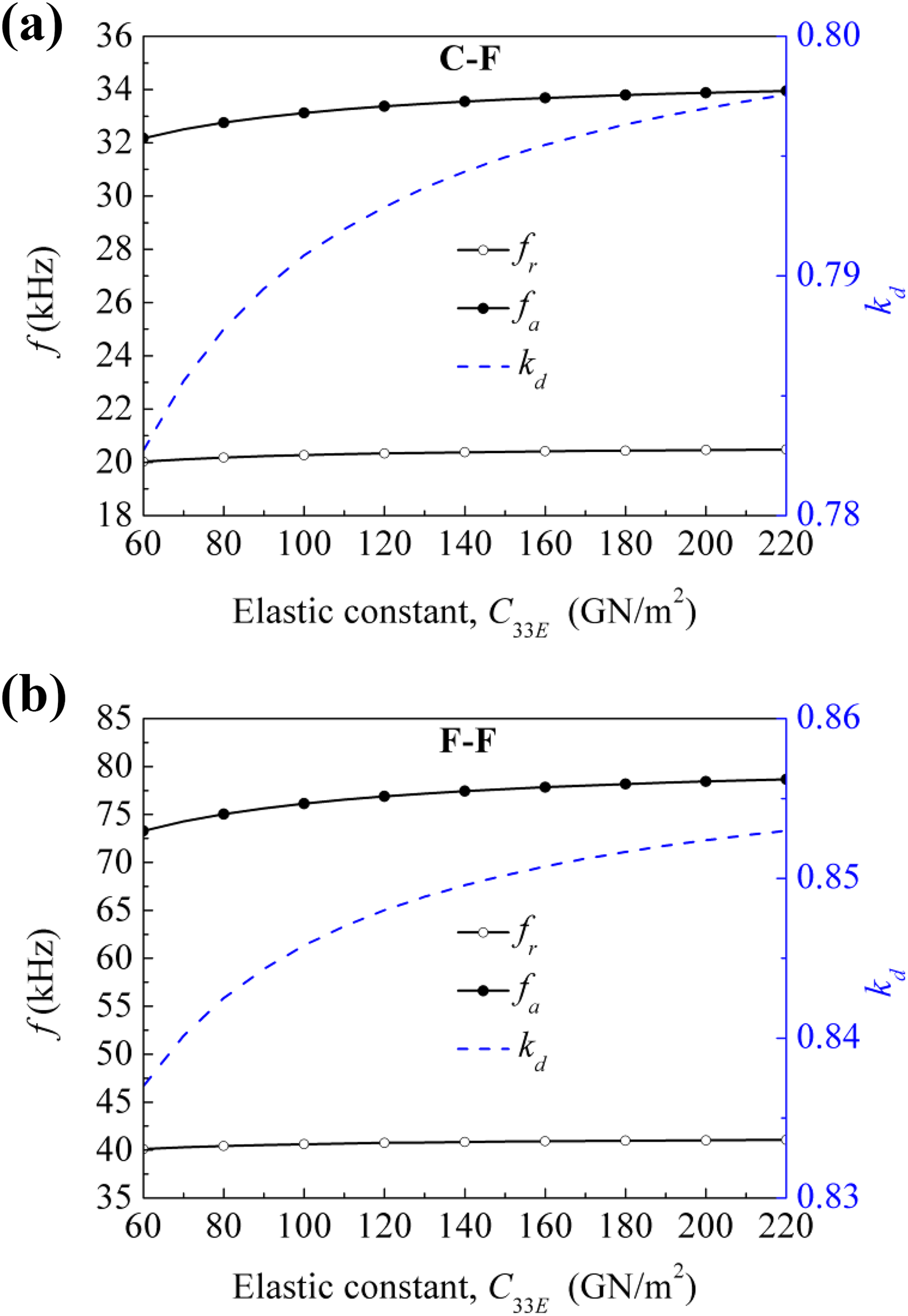
Effects of elastic constant of the electrode on fundamental fr , fa , and kd : (a) C-F state and (b) F-F state. C-F: clamped–free; F-F: free–free.
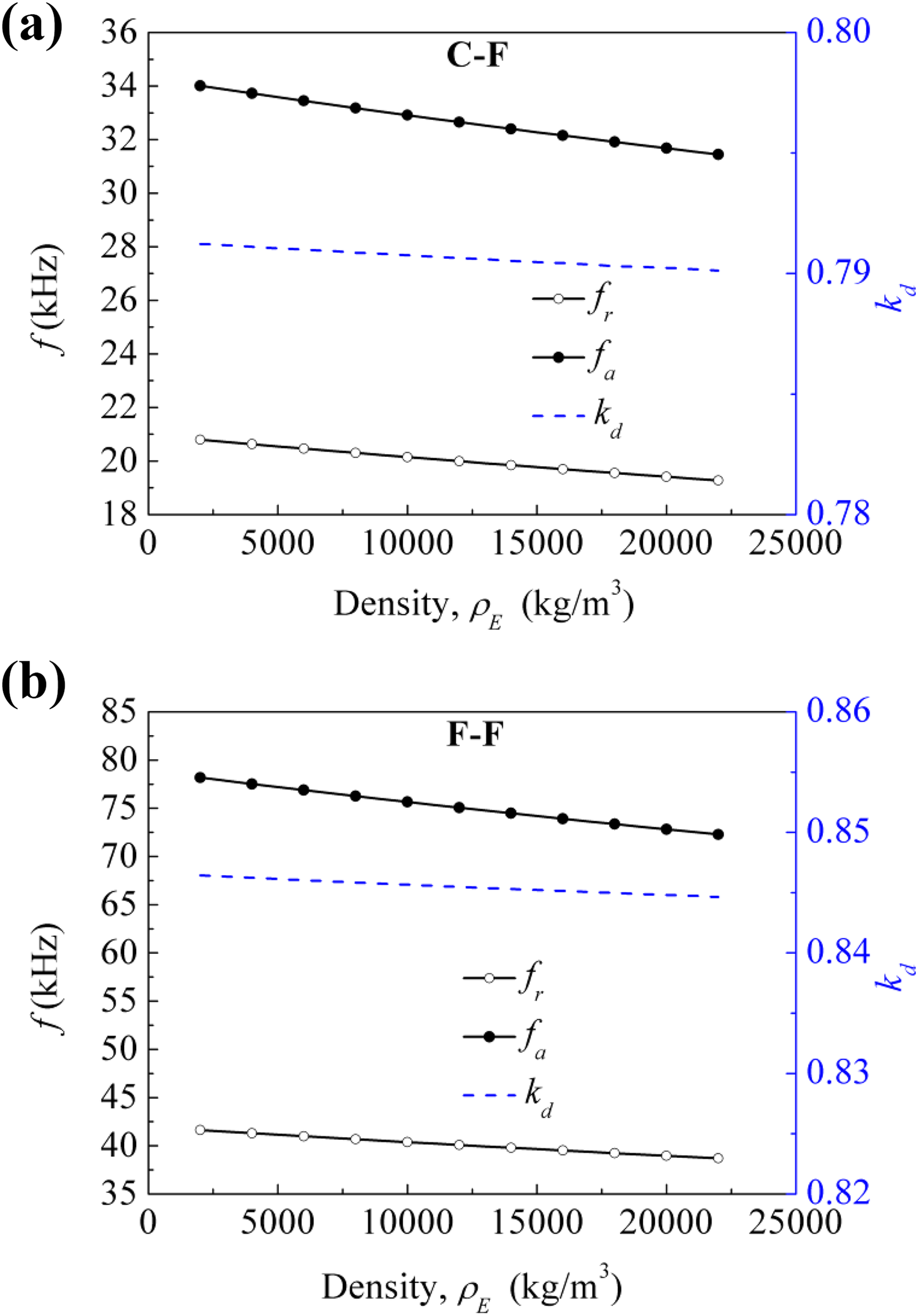
Effects of density of the electrode on fundamental fr , fa , and kd : (a) C-F state and (b) F-F state. C-F: clamped–free; F-F: free–free.
Conclusion
In this article, the exact actuator model of piezoelectric stack was given based on the findings of our previous work. The aim is to evaluate the effects of two key factors including the electrodes and the protective layers on the electromechanical performance of the piezoelectric stack actuator. These two factors are important components in the fabrication of piezoelectric stack actuator, but are not considered in most of the theoretical studies. The correctness of the proposed actuator model was validated by comparing it to the results in the earlier literature and the experimental results and was employed to analyze the effects of the electrode thickness, the thickness of the protective layer, and the electrode type on the electromechanical characteristics. The main findings can be found as follows. With the increase of the electrode thickness, the fundamental fr
, fa
, and kd
of the C-F and F-F states are decreased. With the increase of the thickness of the protective layer, the fundamental fr
and fa
of the C-F and F-F states are decreased. However, the fundamental kd
of these two states has a reverse rule. For the C-F state, it is decreased, while it is increased for the F-F state. Among six electrode types (H62-Brass, Ni, Al, Cu, Ag, and Pt), the actuator with Ni electrodes has the maximum fundamental fa
and kd
for the C-F and F-F states, while the actuator with Al electrodes has the maximum fundamental fr
. With the increase of the elastic constant of the electrode, the fundamental fr
, fa
, and kd
of the C-F and F-F states are increased. With the increase of the density of the electrode, the fundamental fr
, fa
, and kd
of the C-F and F-F states are decreased. Compared to the density, the elastic constant is the dominant factor for the fundamental kd
. Neglecting the electrodes and the protective layers in the actuator model will result in the inaccurate prediction, especially for the thicker ones.
Footnotes
Declaration of conflicting interests
The author(s) declared no potential conflicts of interest with respect to the research, authorship, and/or publication of this article.
Funding
The author(s) disclosed receipt of the following financial support for the research, authorship, and/or publication of this article: This work was supported in part by the National Natural Science Foundation of China (51708025, 61671068, and 11872105) and in part by the Fundamental Research Funds for the Central Universities (FRF-TP-19-023A2).
Appendix 1
where