
Abstract
There are three motion stages for an industrial robot manipulator, including the acceleration stage, the constant velocity stage, and the deceleration stage. Aiming at reducing the residual vibration of the manipulator after the movement of the deceleration, a new method is proposed by configuring the movement parameters of the flexible manipulator. Firstly, we conduct experiments to verify a numerical vibration model of the manipulator, and then, we analyze the vibration suppression effect under different conditions based on the numerical model. The results show that in the range of one movement, the residual vibration can be well suppressed when the acceleration and deceleration time are set as a positive integer to the natural period of the manipulator operation; otherwise, the vibration suppression effect is not obvious and proportional to the difference between the acceleration/deceleration time and the manipulator natural period.
Introduction
Manipulators are widely used in different applications, with broad application prospects, including industry, aerospace, and marine development,1–4 and have attracted the attention of many researchers. Compared with rigid-linked manipulators, flexible manipulators have the advantages of low energy consumption, large operating space, high efficiency, fast and accurate response, and lightweight structure.5–7 However, flexible manipulators usually vibrate and deform during movement. Especially, in a complex environment, the vibration of the elastic flexible structure will reduce the control accuracy and service life of the system, and even cause the system unstable.8–11 Therefore, vibration reduction is worth investigating.
The vibration control methods of flexible manipulators are generally divided into passive control and active control. Passive control mainly suppresses the vibration of the system by adding damping to the system and using the damping characteristics of suitable materials. This is a simple, effective, and widely used method to suppress the vibration of the manipulators. The passive control requires external control device to gradually stabilize the system, and is restricted by factors such as mechanical structure and damping material, which make it difficult to implement in many applications.12,13 The active vibration control does not rely on external devices and can utilize external input energy to achieve high-performance control; so, it has good controllability and can easily meet high control requirements. However, most active vibration control methods require specific sensors to measure specific motion parameters that are required to drive the actuator to generate accurate force or torque outputs14,15; as a result, the actuator will inevitably bring certain disturbances to the original control system, which may degrade the system control performance. In order to solve this problem, computation-costly active control algorithms and expensive external devices are often used to suppress the vibration of the flexible manipulators. For example, Wu et al. 16 proposed a vibration control of a piezoelectric actuator on the L-shaped manipulator. He et al. 17 designed a neural network controller to suppress the vibration of a flexible manipulator system. Cui et al. 18 proposed a particle swarm optimization (PSO) method to study the motion trajectory of the manipulator, which can reduce the vibration of the flexible manipulator. Yavuz et al. 19 applied the exponential harmonic velocity excitation to control the residual vibration of a single-link flexible manipulator. Annisa et al. 20 developed an intelligent evolution controller of a flexible manipulator by finding the suitable trajectory planning for vibration reduction. He et al. 1 used a boundary controller to drive the motion of a flexible manipulator and track the given angular position. Although these active control methods have been proved effective for the vibration suppression of the flexible systems, the controller structure and computation are very complex, and some specific parameters of the system are difficult to be accurately measured, which hinders their practical applications. Hence, it is necessary to propose a simple and effective vibration suppression method for the flexible manipulators.
Recently, the surrogate model of flexible manipulator is recognized to be a potential solution to solve the aforementioned issue. By establishing a surrogate model of the flexible manipulator, it is possible and convenient to develop efficient and effective vibration controllers. Bai et al. 21 proposed a surrogate model of a two-link flexible manipulator for reliability optimization. The surrogate model significantly reduced the complexity of the analysis of the flexible manipulator. Fei et al. 22 used the deep learning to establish the surrogate model of a flexible manipulator, and Li et al. 23 adopted the Kriging technique to establish the surrogate model. Wang et al. 24 employed the digital twin to build the surrogate model of a flexible manipulator. However, these excellent research studies did not perform vibration control based on the surrogate models. It is crucial to develop a practicable vibration controller for the flexible manipulators based on surrogate model strategy.
According to the configuration of the three-stage motion time of the flexible manipulator, this paper proposes a practical, effective, and easy-to-implement vibration suppression method. The system does not require special control algorithms and other complicated steps, and the vibration of the flexible manipulator can be eliminated through reasonable configuration of motion parameters. The rest of this paper is organized as follows. In the section Introduction, the reliability of the first-order mode of the flexible manipulator is verified. The section Simulation Reliability Verification sets the motion parameters of the flexible manipulator, performs the motion simulation, analyzes the vibration suppression effect, and discusses the problems encountered in the analysis process. The results of this paper are summarized in the section Vibration Suppression Effect Analysis.
Simulation reliability verification
Natural frequency measurement of flexible manipulator
Modeling research on manipulator generally considers the manipulator to be equivalent to a variable cross-section beam. At the same time, the variable cross-section beam material has the same effect as flexibility beam, so that the variable cross-section beam can meet the load-bearing capacity of the manipulator, and can also reduce the weight of the manipulator so that save materials and costs.25,26
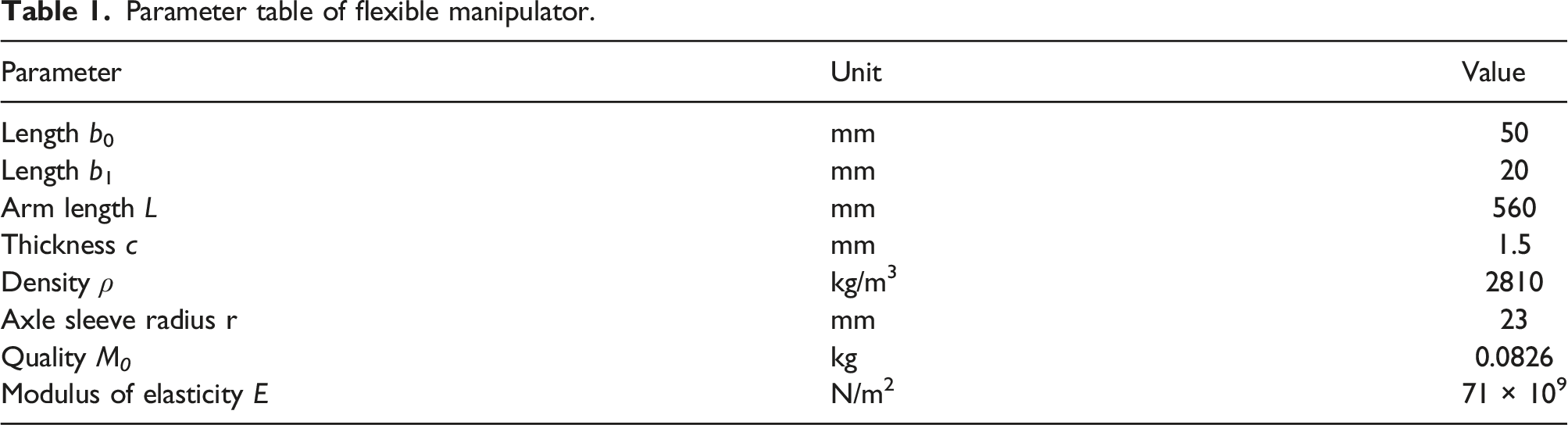
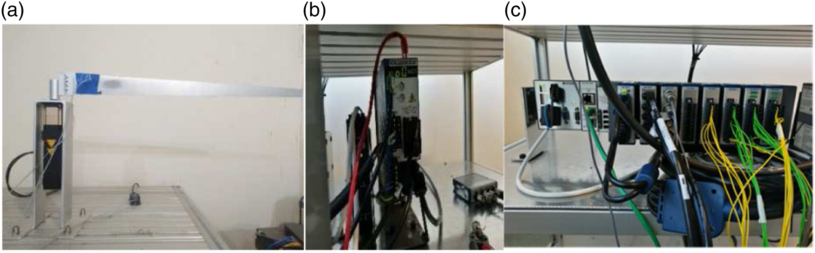
The material of the flexible manipulator studied in this paper is aviation aluminum. The model is shown in Figure 1, and the material parameters are shown in Table 1. One end of the flexible manipulator is fixed on the shaft of the motor by a fixing device, and the other end is in free state. Figure 2 shows the experimental platform for vibration control of the flexible manipulator. The experimental control system includes two parts; the first part is the DC motor control module, which realizes the real-time control of the DC motor; the second part is the data acquisition module, which uses the strain gauge measurement system to realize the system’s real-time vibration test and data collection. The experimental system is implemented by NI Labview real-time module and Compact RIO measurement control system. The Compact RIO system consists of a processor, a user programmable controller, and one or more signal conditioning I/O modules provided by NI or a third party, these modules can directly connect to the sensor.
27
Flexible manipulator model. Parameter table of flexible manipulator. Vibration suppression experiment platform. (a) Flexible manipulator. (b) Servo driver. (c) Measurement and control system.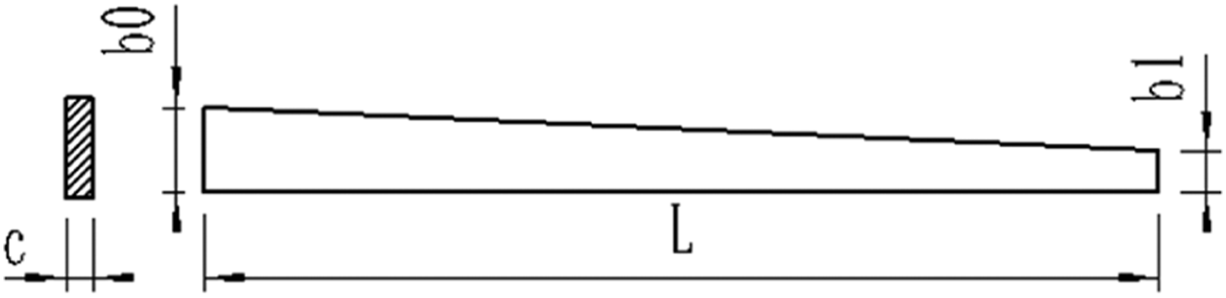
For the single-link flexible manipulator studied in this paper, when the driving torque frequency remains at a low state, the first-order mode can meet the accuracy requirements.
28
Therefore, the first-order mode is used for this situation. The natural frequency of the aviation aluminum material used in this paper is obtained by the attenuation method. The natural frequency of the system is defined as the resonant frequency generated by the system when it is forced to move. Therefore, it is suitable to hit the flexible manipulator with a pulse hammer for data collection. The data acquisition system composed of NI CRIO-9046 embedded controller and NI9237 acquisition card is used to transmit the strain data on the strain gauge to the upper computer. Use the Labview control software to display the changing waveform in real time, and save the real-time data, shown in Figure 3. After processing the data by MATLAB software, the first-order natural vibration frequency of the flexible manipulator can be obtained by fast FFT (Fast Fourier Transform), as shown in Figure 4. Vibration attenuation waveform. FFT of vibration response.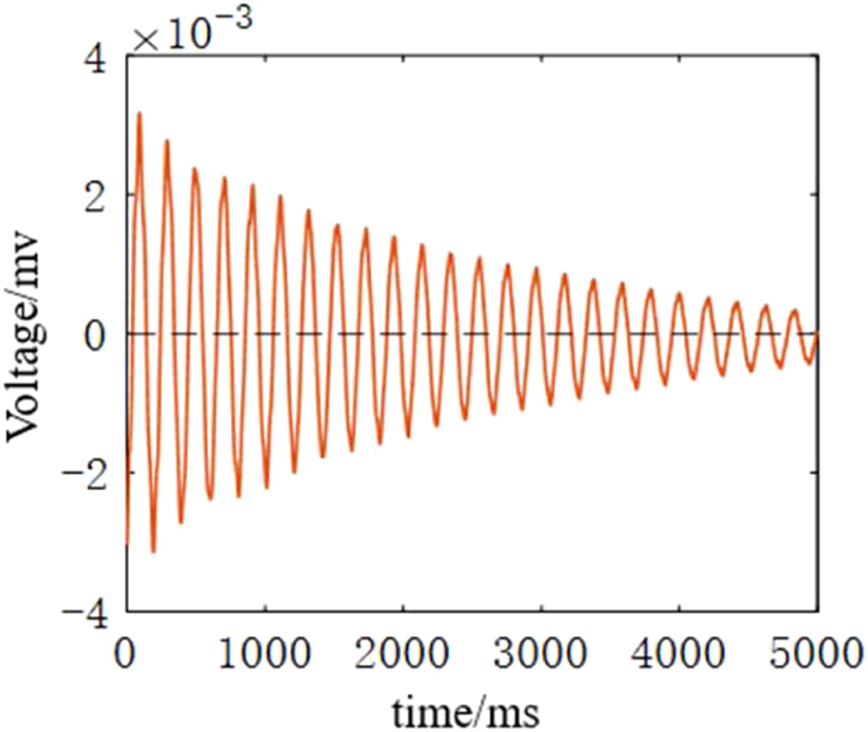
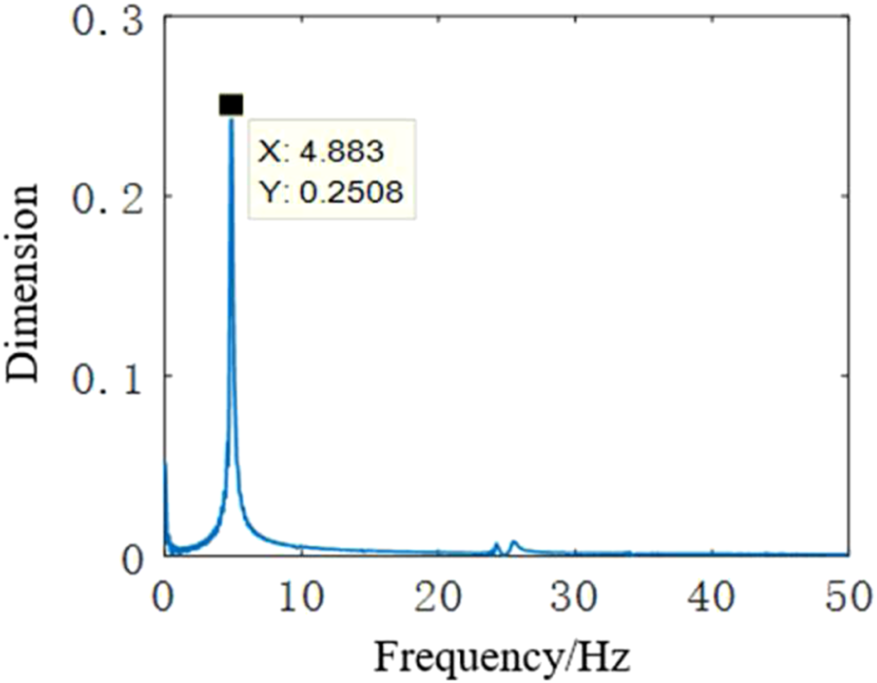
It can be seen from Figure 4 that for the aviation aluminum flexible manipulator proposed in this paper, the first-order natural frequency of the aviation aluminum flexible manipulator is 4.883 Hz measured by experiments, which is the natural vibration period T = 0.20479 s of the aviation aluminum flexible manipulator.
Simulation model
In order to verify the effect of the three-level motion speed configuration method proposed in this paper, the simulation model of the flexible manipulator control system is established by using the SIMULINK visual simulation software. As shown in Figure 5, the summation of two Ramp modules and Saturation modules is used to form the required input speed signal. The Transfer Fcn module is a system transfer function module, and each parameter variable in the module corresponds to the position of each parameter variable of the transfer function. The transfer function of the aviation aluminum flexible manipulator system is Three-level motion velocity configuration vibration research simulation model.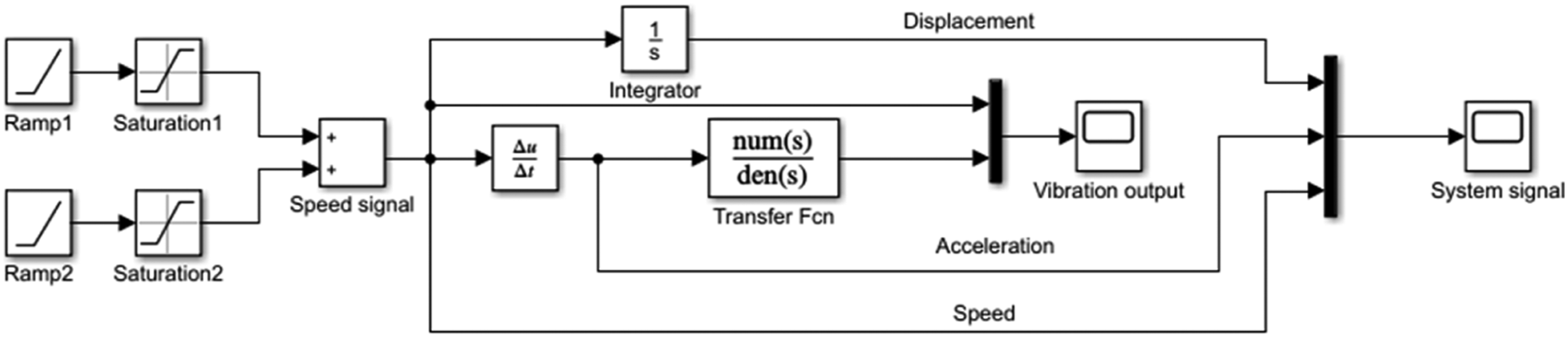
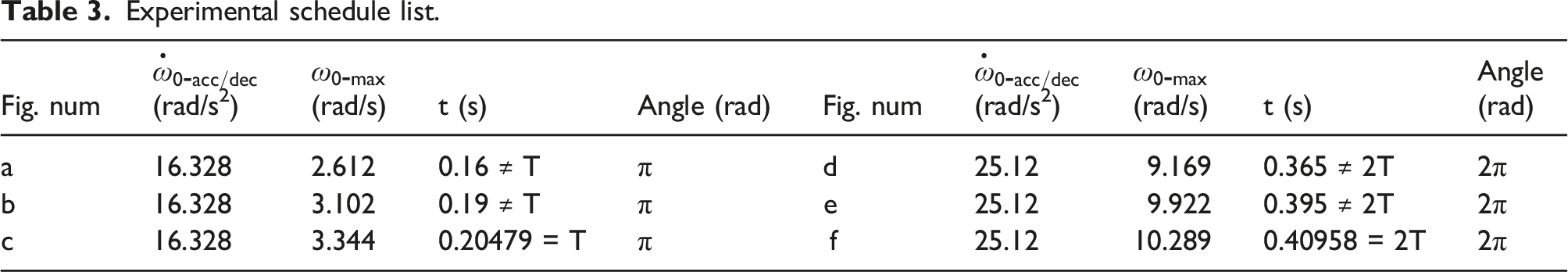
The experimental plan is determined
Experimental schedule list.
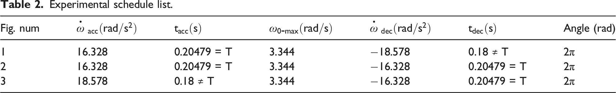
The experimental and statistical results obtained based on the experimental plan are shown in Figure 6 Acceleration and deceleration time configuration verification results.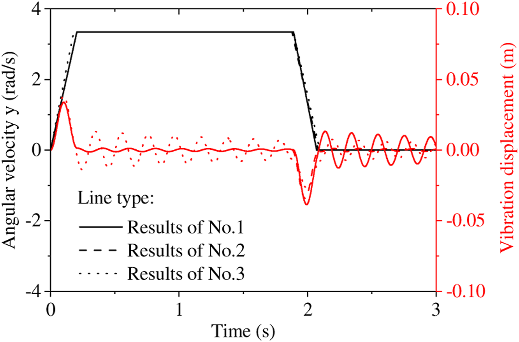
It can be seen from Figure 6 that when the acceleration time is the natural period of the manipulator, the vibration at the constant velocity is significantly reduced; the residual vibration increases when the deceleration time is not the natural period of the manipulator. In addition, when the deceleration time is not the natural period of the manipulator, the residual vibration is more obvious. This means that the residual vibration is obvious when the acceleration and deceleration time are not the natural period of the manipulator (there may be a multiple relationship, considering the content of subsequent research, here only verify the condition when the acceleration and deceleration time are the natural period of the manipulator). This is contrary to the expectation of active control, so follow-up studies are under the condition which the acceleration and deceleration time are equal to the natural period of the manipulator or its positive integer multiples.
Simulation result verification
Experimental schedule list.
In order to compare the simulation and experimental results, the residual vibration amplitude is used for evaluation. The results are shown in Figure 7, and the statistical results are shown in Table 4. Comparison results of experiment and simulation under different conditions (a) The simulation and experimental results when the angular acceleration is 16.328rad/s−2, acceleration time is 0.16s and angular is Π rad; (b) The simulation and experimental results when the angular acceleration is 16.328rad/s−2, acceleration time is 0.19s and angular is Π rad; (c) The simulation and experimental results when the angular acceleration is 16.328rad/s−2, acceleration time is 0.20479s and angular is Π rad; (d) The simulation and experimental results when the angular acceleration is 25.12rad/s−2, acceleration time is 0.365s and angular is 2Π rad; (e) The simulation and experimental results when the angular acceleration is 25.12rad/s−2, acceleration time is 0.395s and angular is 2Π rad; (f) The simulation and experimental results when the angular acceleration is 25.12rad/s−2, acceleration time is 0.395s and angular is 2Π rad. Simulation and experiment error.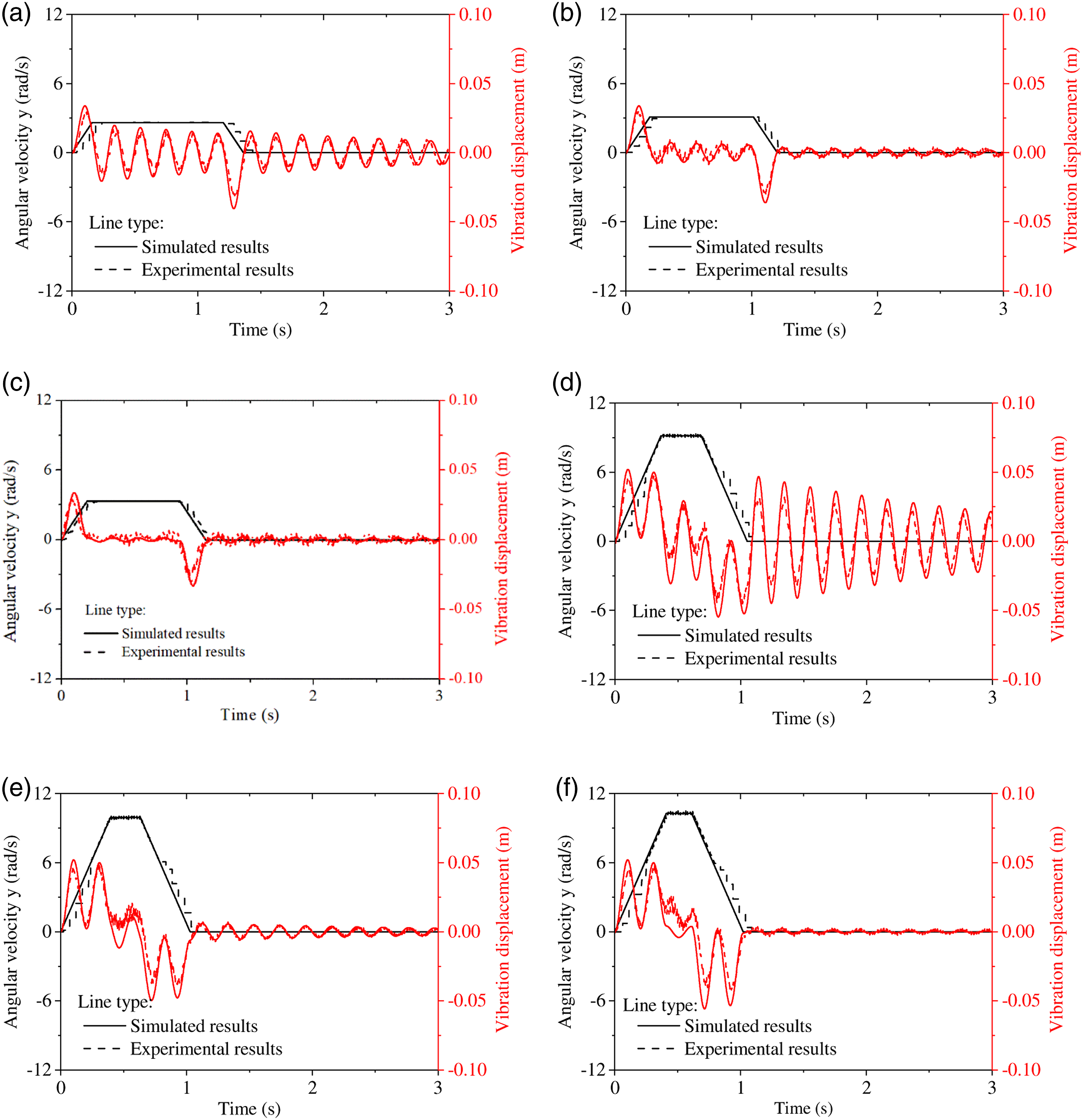
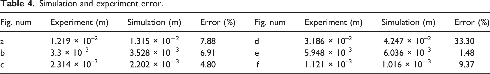
It can be seen from Table 4 that the simulation and experimental errors are within 10% except the fourth group. The reason for the larger error of the fourth group is that its acceleration and deceleration time deviate from the natural period of the manipulator, which make the vibration suppression effect worse; what is more, the vibration is relatively obvious due to the large acceleration at that moment. From the free oscillation result of the residual vibration, we can see that the accuracy is slowly improving, which may be caused by the range and sampling rate of the sensor. On the whole, the simulation and experimental results meet the error requirements, so the simulation model has enough correctness to study the vibration suppression analysis of the manipulator.
It can be seen from Figure 7 that the experimental data of angular velocity presents a step change in the first period of acceleration and the last period of deceleration. This is affected by the vibration of the manipulator, and is also related to the acceleration and deceleration mechanism of the motor. Even so, the numerical values of the angular velocity of the simulation and the experiment are almost the same, especially in the constant velocity phase. After entering the constant velocity stage, we can see from Figure 7(a)–(c) that the vibration amplitude is increasing smaller during the constant velocity stage when the acceleration and deceleration time are getting closer to the natural period of the manipulator. As can be seen in Figure 7(d)–(f), the acceleration and deceleration time are twice the natural period of the manipulator, the constant velocity time is shorter, so the vibration is relatively irregular, but the trend law is consistent with the former. The reason for the irregular vibration is that when the acceleration time is not the natural period or multiple of the manipulator, the vibration of the manipulator has not yet returned to the original point. At this time, the inertial force suddenly disappears and starts to oscillate freely, and its direction is opposite to the original inertial force, superimpose with the original vibration effect to produce more obvious vibration; when the acceleration time is equal to the natural period or multiple of the manipulator, it is only the result of free oscillation; after entering the constant velocity period, due to the constant velocity time does not constitute a complete free oscillation period, the experimental value fluctuates significantly and does not constitute a complete vibration waveform. Furthermore, the fluctuation of the test data is related to the data acquisition resolution and the accuracy of the strain gauge.
Based on the analysis above, we use the simulation method to further research on the vibration suppression control.
Vibration suppression effect analysis
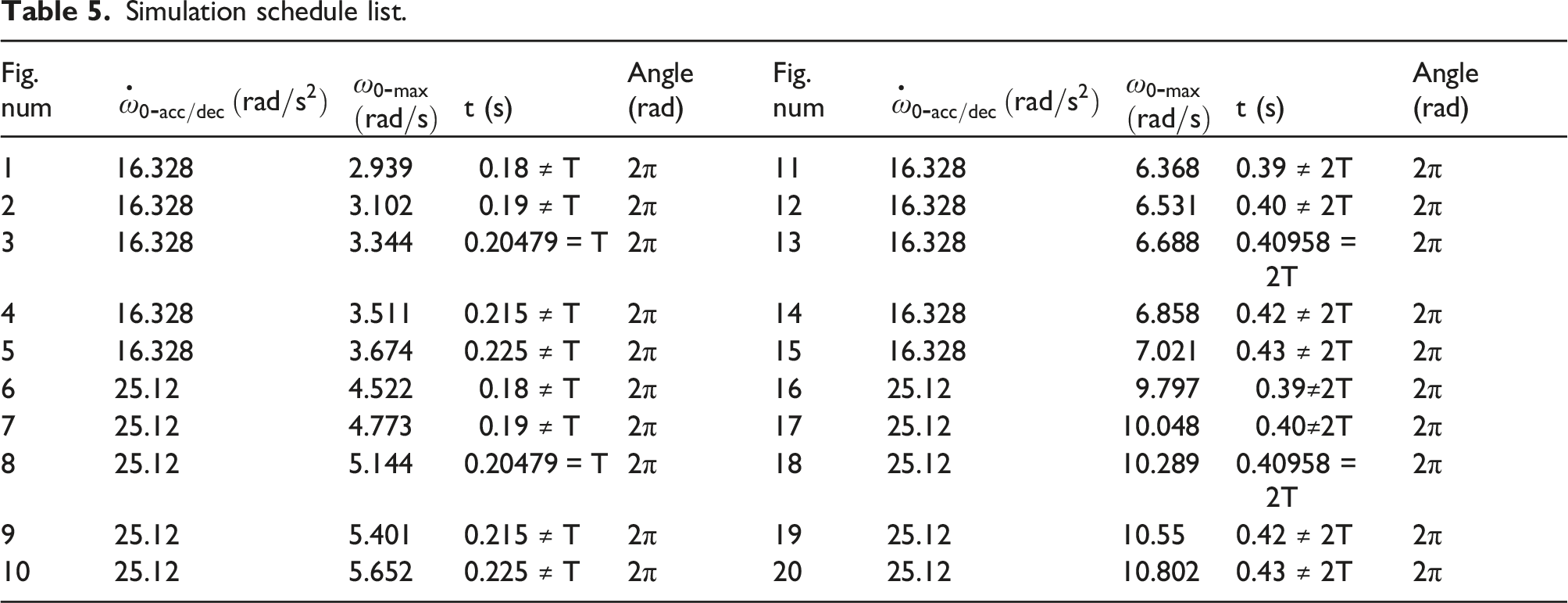
Simulation program arrangement
Simulation schedule list.
Simulation results
The simulation results are shown in Figure 8. The vibration amplitude in the acceleration phase (AV for short), the vibration amplitude in the constant speed phase (MV for short), the vibration amplitude in the residual phase (RV for short), and the residual vibration suppression rate are obtained at the same time for evaluation. The statistical data is shown in Table 6. Among them, the vibration amplitude is the maximum deformation of the end for flexible manipulator during acceleration. The vibration amplitude in the constant velocity stage refers to the maximum deformation of the end of the flexible manipulator during the constant velocity process. The residual phase vibration amplitude refers to the maximum deformation of the end of the flexible manipulator after the end of the movement. The residual vibration suppression rate is Simulation results under different conditions. (a) The simulation results when the angular acceleration is 16.328rad/s−2 and acceleration time is equal or near to T; (b) The simulation results when the angular acceleration is 25.12rad/s−2 and acceleration time is equal or near to T; (c) The simulation results when the angular acceleration is 16.328rad/s−2 and acceleration time is equal or near to 2T; (d) The simulation results when the angular acceleration is 25.12rad/s−2 and acceleration time is equal or near to 2T. Motion parameters and reduction of vibration percentage.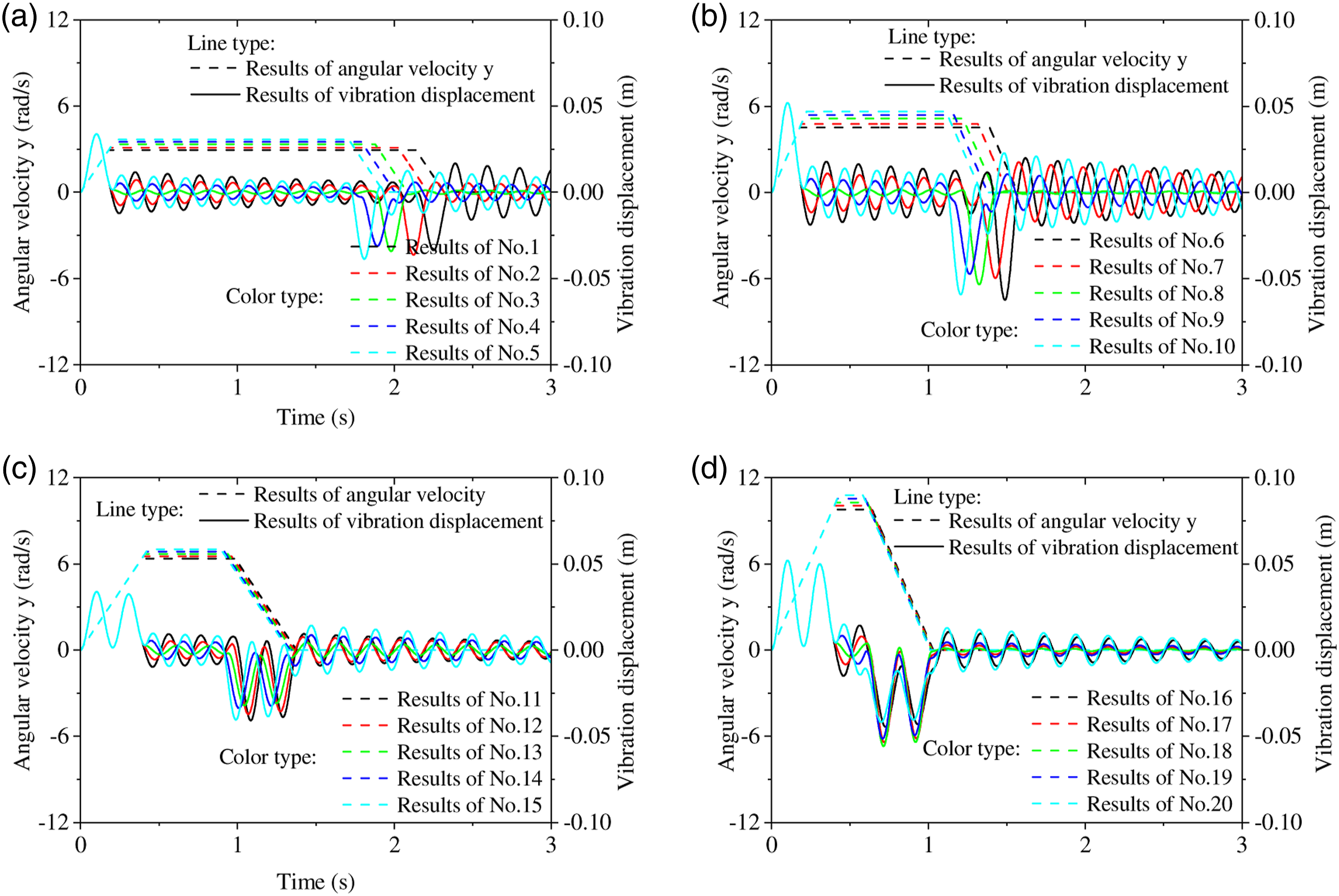
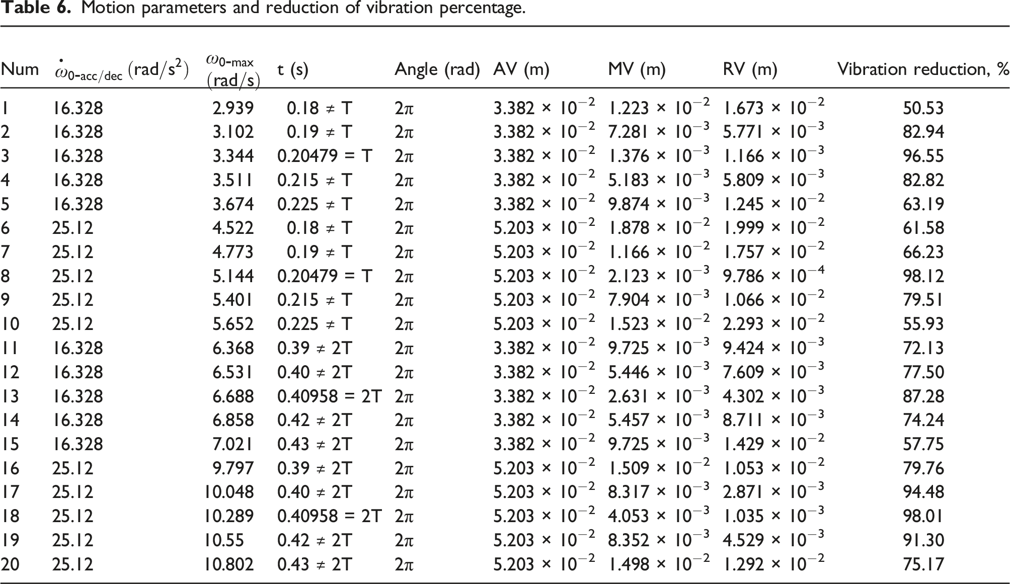
We can tell from Table 6 that when the acceleration/deceleration time is multiple of the natural period of the manipulator, the vibration amplitude is the minimum of the current group data whether in the constant velocity phase or the residual phase. This means that the three-level motion speed configuration proposed in this paper has an obvious suppression effect on residual vibration, with the maximum vibration suppression efficiency reaching 98.12% and the minimum value reaching 87.28%; the vibration amplitude of each group of data is basically unchanged during the acceleration stage; when the acceleration/deceleration time is twice the natural period of the manipulator, the vibration amplitude in the constant velocity phase is almost twice that when the acceleration/deceleration time is equal to the natural period of the manipulator, but the vibration effect in the residual phase shows a different trend; the three-level motion configuration has the same vibration suppression effect when the acceleration/deceleration time is equal to the natural period of the manipulator, and the residual vibration amplitude is almost equal; the vibration amplitude under the condition of large acceleration increases significantly when the acceleration/deceleration time deviates from the natural period; when the acceleration/deceleration time is twice the natural period of the manipulator, the residual vibration amplitude is larger than that when the deceleration time is adjusted as even multiples of the natural period.1,2 The reason is that the vibration does not return to the origin at the constant velocity stage, and the reverse vibration moves toward the origin, and the distance is far (as shown in Figure 8(c)). When the acceleration is large, the overall residual vibration is smaller than that the acceleration is small. This is due to the uncomplete vibration period in the constant velocity stage, and part of the vibration is in the forward direction and part of the vibration in the reverse direction (as shown in Figure 8(d)). Therefore, the three-level motion speed configuration is not suitable for setting a large acceleration/deceleration time, which makes the time in the constant velocity phase greater than the natural period of the manipulator. In addition, when the acceleration/deceleration time deviates from the natural period, the farther the deviation is, the lower the vibration suppression effect, this satisfies under any public conditions.
Conclusion
The motion control method proposed in this paper is used to study the vibration suppression of the flexible manipulator system, the conclusions are as follows: 1. The flexible manipulator adopts a three-level motion control method, and when the acceleration/deceleration time is equal to a positive integer multiple of the natural period of the manipulator, that is, 2. When the acceleration/deceleration time deviates from a positive integer multiple of the natural period of the manipulator, the greater the deviation, the lower the vibration suppression efficiency. 3. When the constant velocity time is too short to form a complete vibration cycle or the manipulator deviates far from the origin, the vibration suppression effect still performs well, but the law is abnormal.
Footnotes
Data availability
All the data can be requested from the corresponding author.
Declaration of conflicting interests
The author(s) declared no potential conflicts of interest with respect to the research, authorship, and/or publication of this article.
Funding
The author(s) disclosed receipt of the following financial support for the research, authorship, and/or publication of this article: This work is supported by the National Natural Science Foundation of China (52005048) and Special Funds for Fundamental Research Business Fees of Central Universities of Chang’an University (300102259504), and Narodowego Centrum Nauki, Poland (No. 2020/37/K/ST8/02748).