
Abstract
The lateral plates are usually used in the field of structural design of acoustic metamaterials (AMs), which can realize the control of AMs on sound waves. Presently, researches on the application of AMs with lateral plates mainly focus on the regulation of sound waves in air media, and rarely involve the research on their underwater acoustic properties. Therefore, a composite acoustic structure is designed by inserting regularly distributed lateral plates into the viscoelastic rubber, and then, the AMs with multiple coupling substructure (AMs-MCS) can be obtained through combining the local resonance structure and functional gradient structure. Based on underwater acoustic calculation model for the functional gradient acoustic structure established by grade finite element method (G-FEM), the underwater sound absorption characteristics of the AMs-MCS are studied, and the influence of each substructure on the acoustic performance of the AMs-MCS is explored. Numerical results indicate inserting gradient-distributed multiple lateral plates inside the homogeneous acoustic structure can improve the sound absorption performance of the acoustic structure in the mid-and high-frequency ranges and the sound absorption frequency band of the acoustic structure can be effectively broadened. Moreover, the sound absorption coefficient of the AMs-MCS is greater than 0.8 at 500Hz-10 kHz, and the average sound absorption coefficient reaches 0.893, thus achieving low-frequency and broadband sound absorption performance.
Introduction
As an important equipment, underwater vehicles have attracted much attention in the field of underwater detection due to their acoustic stealth, maneuverability and assault capabilities. In recent years, with the development of underwater sonar detection technology, the submersible depth of underwater vehicle has also reached the kilometer level, and the corresponding frequency band of sonar detection has also expanded to lower frequencies. Correspondingly, the vibration and noise reduction technology of underwater vehicles also needs to be further improved in response to changes in detection technology, reducing radiated noise and acoustic target intensity within a low-frequency broadband range. Therefore, reducing the acoustic target intensity of underwater vehicle in low and broaden frequency range is the key to improving its acoustic stealth. Anechoic coating is a key technology that can simultaneously suppress the echo and vibration-acoustic response of the vehicles. The application of anechoic coating with better sound absorption properties can reduce the acoustic target intensity of underwater vehicles, and it is widely used in acoustic stealth technology for underwater vehicles.
The anechoic coating with cavity resonance refers to the cavity of different shapes such as spherical, cylindrical, conical and horn-shaped embedded inside the homogeneous material.1–7 It mainly achieves effective absorption of sound waves through cavity resonance, wave mode conversion and intrinsic energy dissipation of viscoelastic materials, and low-frequency sound absorption performance can be achieved, which has been widely used on underwater vehicles. However, since the anechoic coating with cavity resonance cannot withstand high hydrostatic pressure, it will deform under the water pressure, and the low-frequency sound absorption effect will become worse or even the sound absorption function will be lost. Therefore, high hydrostatic pressure limits the application of the anechoic coating with cavity resonance when considering the control of low-frequency sound waves.
In recent years, the local resonance regulation mechanism for low-frequency sound waves has been proposed, which can break the mass density law of traditional acoustic structures and has the ability to control large-wavelength sound waves through a small-scale structure, providing new ideas of regulation and control for underwater low-frequency sound wave control. Liu et al. 8 designed a three-component 3D local resonant phononic crystal, and the proposed local resonance phonon crystals break the scale limitation of Bragg scattering phonon crystals and provide a new idea for realizing the control of low-frequency sound waves by small-scale materials. Li et al. 9 designed a new structure composed of soft rubber localized vibrators distributed in a water matrix and explicitly proposed the concept of AMs, which refers to some artificial materials with extraordinary acoustic properties that natural materials do not possess. Derived from the development of local resonance structure, it can realize basic properties such as negative parameters and anisotropy, and can regulate the refraction, scattering and absorption of sound waves, thus achieving different acoustic regulation functions.10–12
Based on the special physical effects of AMs, many researches on the underwater sound absorption properties of AMs have been carried out in recent years. Zhao et al.13–16 introduced the local resonance effect into the underwater sound absorption structure, revealing the sound absorption mechanism of the underwater local resonance phonon crystal, systematically investigating the influence of the mode of the internal resonators, the backing of the structure and the position of the resonators on the sound absorption performance of the acoustic structure. Zhang et al.17,18 embedded elastic plate with different size into the matrix in a certain gradient form, and introduced multiple resonance modes into the matrix structure to increase the resonance modes of the acoustic structure, which can effectively broaden the absorption band of the acoustic structure. Jiang et al.19,20 introduced the woodpile structure into the matrix material and designed a phononic woodpile structure that can realize the performance of underwater broadband sound absorption. Later, the multi-scale woodpile structure was networked to design a phonon glass structure with both pressure resistance and broadband sound absorption, providing a new way and method for the research of underwater broadband sound absorption. Gao et al.21–24 respectively proposed the AMs with a spiral metal ring embedded in the elastic layer and the AMs combing conical cavities and resonators. Numerical results showed that these two kinds of AMs can effectively convert medium and low-frequency longitudinal waves to shear waves, and achieve broadband sound absorption performance in the frequency band below 10 kHz. Duan et al. 25 introduced rubber layer and embedded metal neck into the Helmholtz resonator to design a lightweight tunable AMs, the strong absorption effect of low-frequency sound waves can be achieved by adjusting the geometric parameters of the AMs. Lee et al. 26 designed an underwater acoustic stealth metasurface by using the shunt pore-conduit hybrid resonance unit. The research proved that, on the basis of the coupling resonance mechanism generated by the shunt pore-conduit hybrid resonance unit, the resonant sound absorption frequency was adjusted by adjusting the geometric parameters and the broadband sound absorption performance can be obtained. Zhang et al.27,28 proposed a new semi-active anechoic coating with periodic sub-wavelength piezoelectric array for the acoustic stealth technology of underwater vehicles. The theoretical modeling, multiple energy dissipation and sound absorption mechanism of the semi-active anechoic coating were studied, and the sound absorption characteristics of the semi-active anechoic coating under different hydrostatic pressure are studied as well.
In general, although the AMs has better regulatory performance for low-frequency sound waves compared with traditional anechoic coating, the narrow sound absorption band is a key factor restricting the application of its underwater sound absorption due to the inherent property of the local resonance mechanism. The general method of broadening the local resonance acoustic absorption band is to adjust the elastic constant matching of the component materials and the geometric structure of the local resonance unit. Most of these methods are based on changing the intrinsic properties of the local resonance unit, and the absorption band cannot be broadened effectively. From the perspective of local resonance sound absorption mechanism, the key to realize broadband strong sound absorption is to generate more resonance modes at different frequency points in the broadband range. The feasible method is to introduce multiple resonant elements through composite multi-scale, multi-structure combination, multi-resonator coupling, etc. The new resonance mode can be generated by the coupling between multiple resonant elements and the sound absorption band can be broadened. At present, the means to broaden the sound absorption band of the AMs are not abundant, so it is necessary to do further research on the low frequency and broadband sound absorption mechanism of the AMs.
In order to achieve low frequency and broadband sound absorption performance under high hydrostatic pressure, the AMs-MCS are designed through combining the local resonance structure and functional gradient structure. The underwater sound absorption characteristics of the AMs-MCS are studied based on underwater acoustic calculation model for the functional gradient acoustic structure, and the low frequency and broadband sound absorption mechanism of the AMs is also revealed. Moreover, the influence of each substructure and hydrostatic pressure on the acoustic performance of the AMs-MCS is explored. It provides technical support for the development of underwater low frequency and broadband anechoic coating.
Acoustic model and calculation method
Model of AMs-MCS
Multiple lateral plates with a certain gradient distribution are embedded into the rubber matrix, and a composite acoustic structure with multiple lateral plates is designed. The underwater sound absorption model for composite acoustic structure with multiple lateral plates is shown as Figure 1. It can be seen that the rubber layer is laid on the surface of the steel plate, and the multiple lateral plates are embedded into the rubber matrix which is periodically distributed along the x direction. The width of the lateral plates along the x direction is distributed with a gradient form along the thickness direction of the acoustic structure, and the length of the lateral plates structure along the y direction is infinite. Schematic diagram of underwater sound absorption model for composite acoustic structure with multiple lateral plates.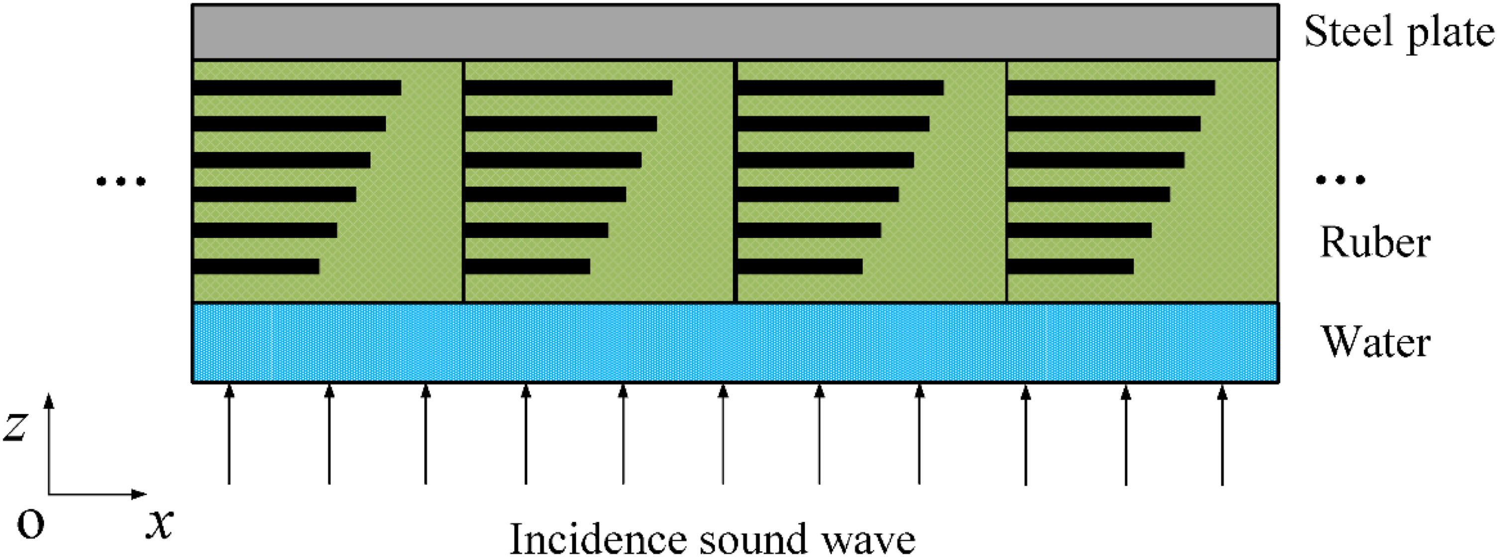
Figure 2 shows a unit cell of composite acoustic structure with multiple lateral plates. In Figure 2(a), the cell of the acoustic structure contains lateral plates with gradient distribution, while the lateral plates with uniform distribution are inside of the acoustic structure in Figure 2(b). The thickness of the rubber layer is h
a
, the thickness of the steel plate is h
s
, the distance between adjacent cells is a, and the thickness of the lateral plates is t
p
. For the lateral plates with gradient distribution, its initial width is b1, and the width changes along the z direction is b
i
= b1+(i-1) × (a-b1)/n, (i =2,3,…,n), where n is the number of lateral plates, and the distance between adjacent lateral plates is △h = h
a
/n. The backing side of the steel plate is the semi- infinite air, while the other end of the rubber layer is the semi-infinite water. The sound wave is vertically incident along the z direction through the water medium. Schematic diagram of a unit cell of composite acoustic structure with multiple lateral plates.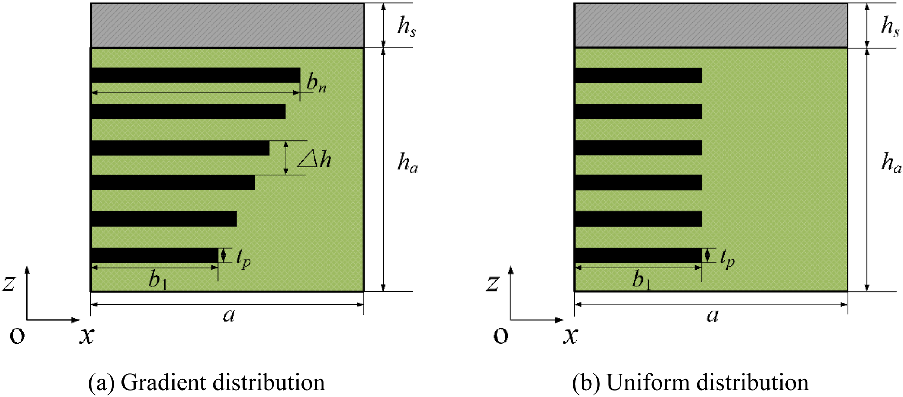
Based on the local resonance acoustic structure (Figure 3(a)), acoustic structure with multi-resonator (Figure 3(b)), gradient cavity structure (Figure 3(c)) and acoustic structure with multiple lateral plates(Figure 3(d)), the AMs-MCS is designed by combining with those four substructures. Figure 4 shows the physical model of underwater sound absorption of the AMs-MCS. The matrix structure is composed of functionally graded materials (FGMs) and rubber, and the single resonator, the multi-resonator, the gradient cavities and the multiple lateral plates are distributed inside the FGMs and rubber, respectively. The AMs-MCS is laid on the surface of the steel plate, and the other side of the AMs-MCS is semi-infinite water. Plane waves are vertically incident along the z direction from semi-infinite water. Schematic diagram of each substructure of the AMs-MCS. Physical model of underwater sound absorption of the AMs-MCS.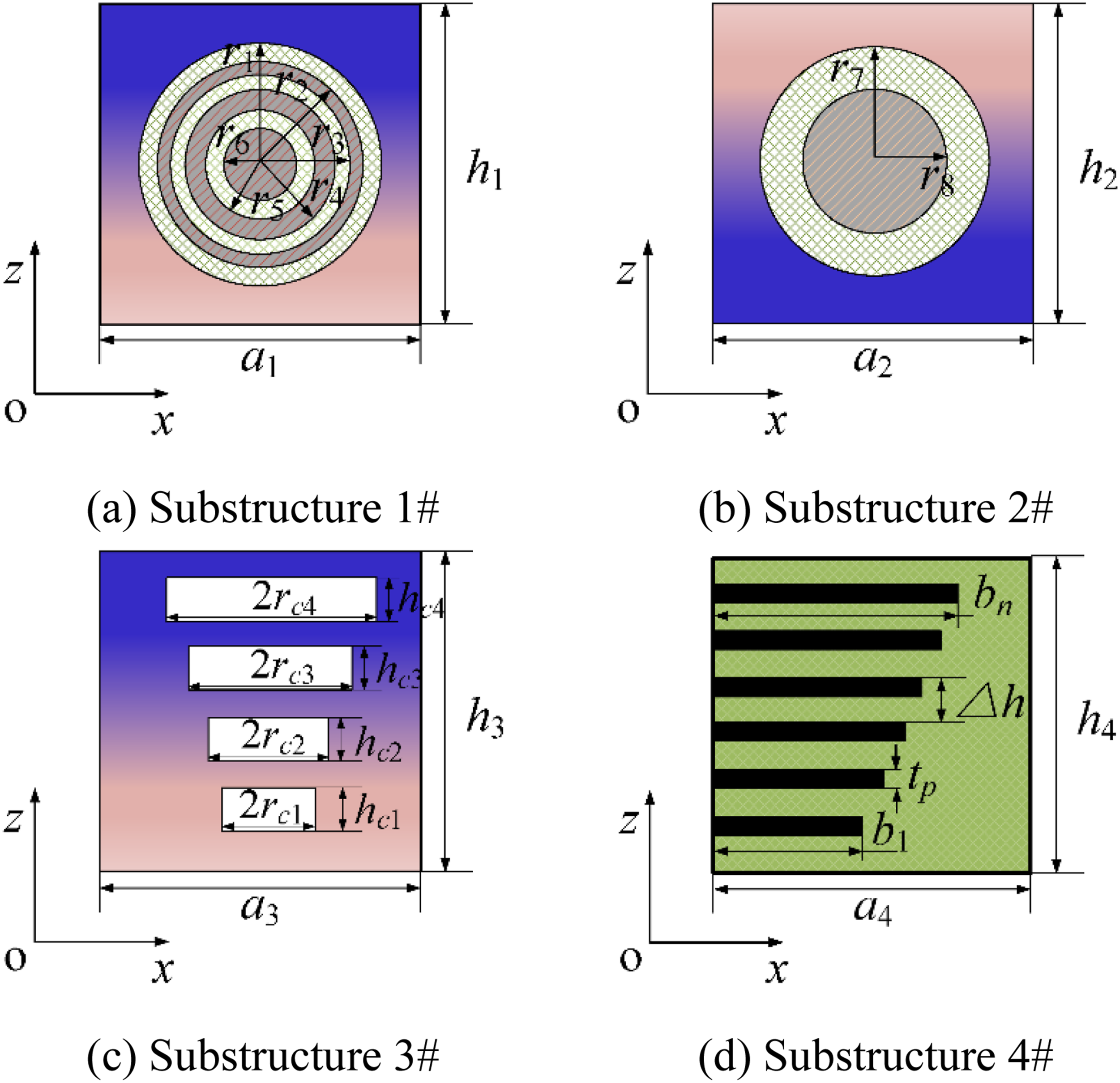
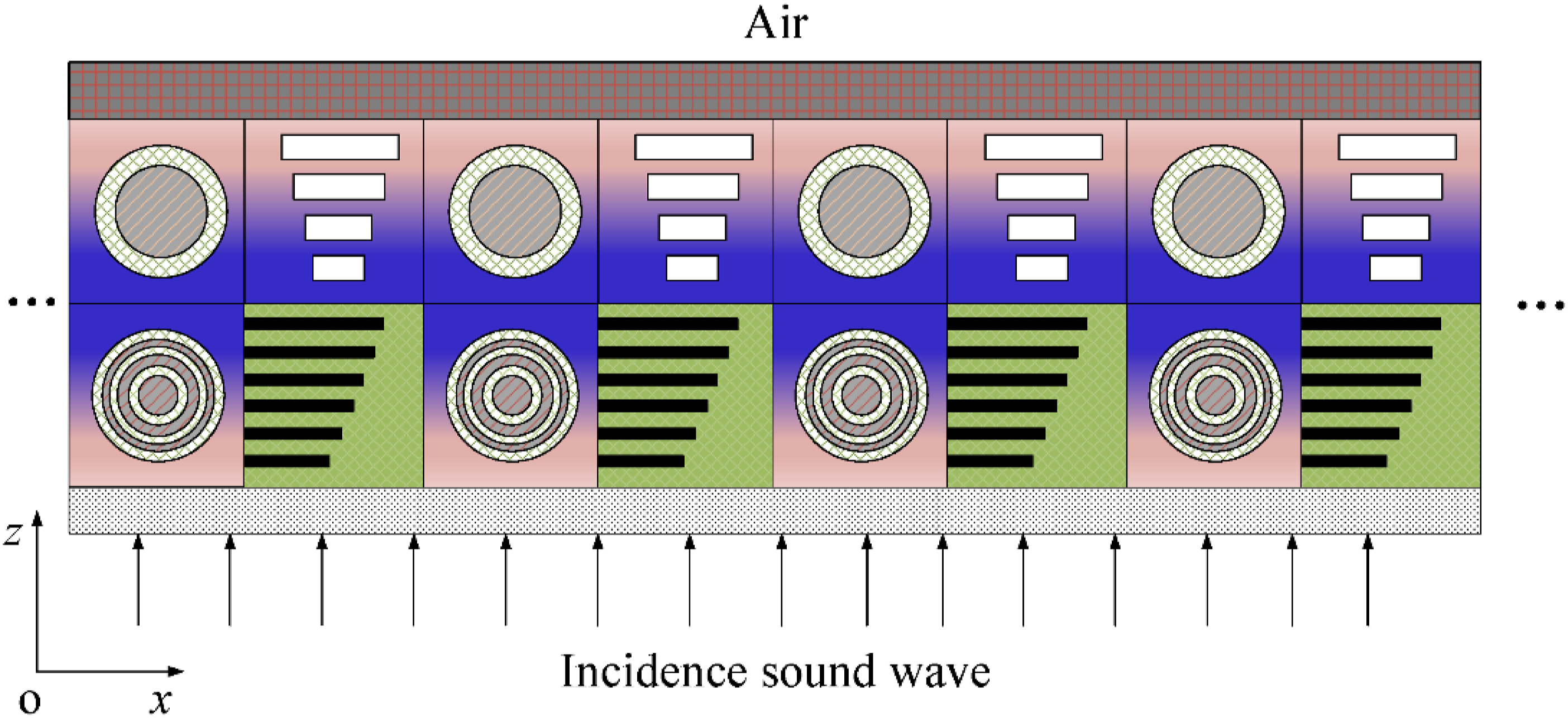
The unit cell of the AMs-MCS on xoz plane is shown in Figure 5. It can be observed that, a unit cell of the AMs-MCS consists of four substructures, named substructures 1#, 2#, 3#, and 4#, respectively. In substructure 1#, FGMs contain the multi-layered spherical resonator, and each resonator is connected by coating layer. The radius of the spherical vibrator and the cladding layer are r1∼r6, the gradient index of the FGMs is P1, the thickness of the FGMs is h1, and the lattice constant of the substructure along the x and y directions is a1. In substructure 2#, FGMs contain single spherical resonator, the radius of the spherical resonator and the coating layer are r7 and r8, the gradient index of the FGMs is P2, the thickness of the substructure 2# is h2, and the lattice constant of the substructure 2# along the x and y directions is a2. In substructure 3#, the FGMs are embedded with cylindrical cavities with gradient distribution, and the cavity radius increases successively along the thickness direction, namely, rc1, rc2, rc3, and rc4, respectively. The heights of cavities are hc1, hc2, hc3, and hc4, respectively. The material distribution of FGMs is the same as that of substructure 2#, and the gradient index is P2. The thickness of the structure is h3, and the lattice constant of the substructure 3# along the x and y directions is a3. In substructure 4#, the matrix material is rubber, which contains lateral plates with gradient distribution. The thickness of the rubber layer is h4, and the lattice constant of the substructure 4# along the x and y directions is a4. The geometric description of the lateral plates is the same as that in Figure 2. Cross-sectional view of a unit cell of the AMs-MCS on xoz plane.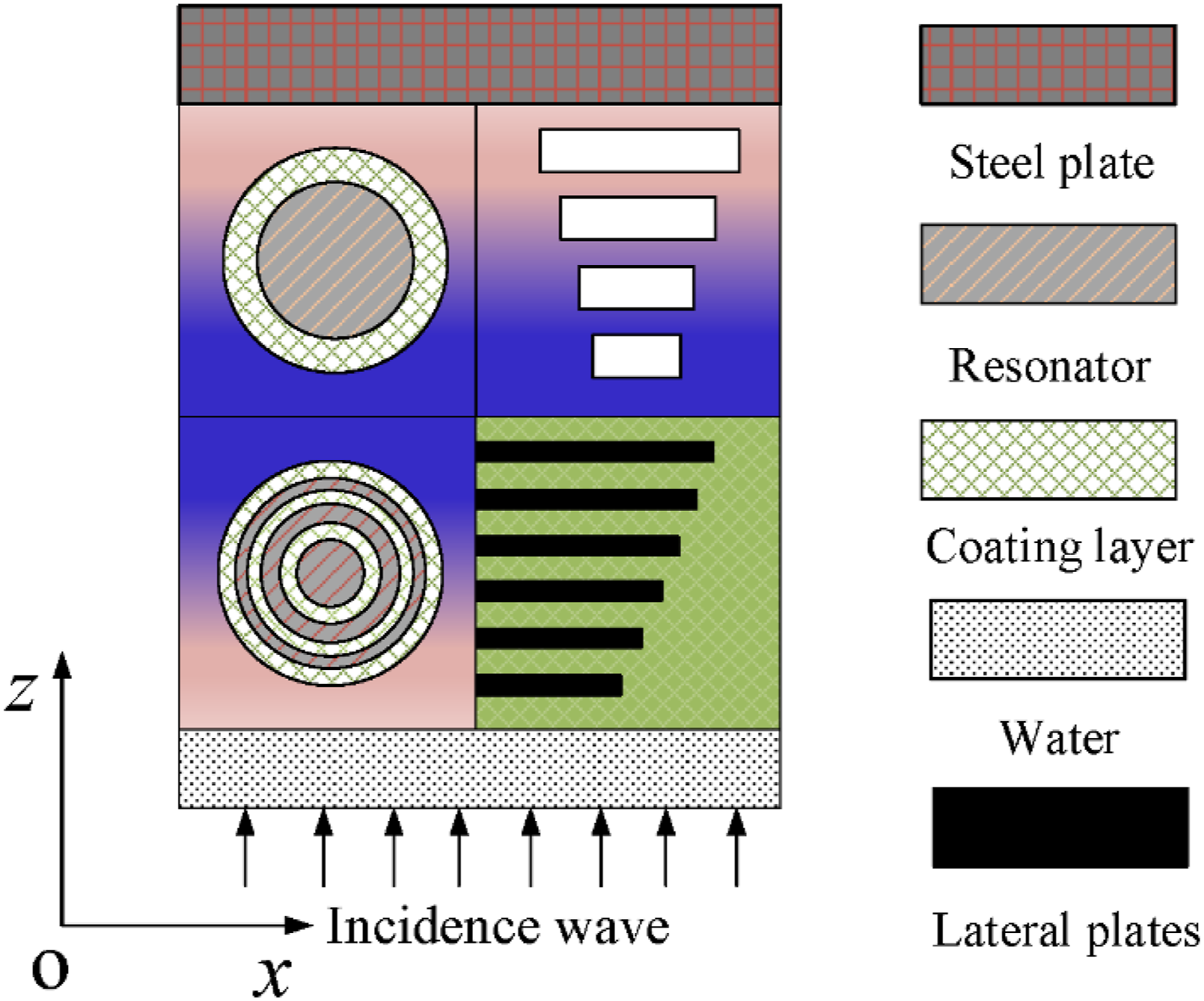
Acoustic calculation for AMs-MCS
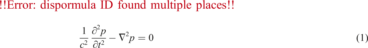
If the fluid domain is homogeneous and incompressible, the acoustic wave equation can be expressed as:
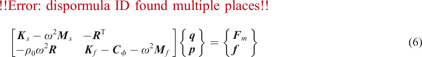
The governing equation can be derived by discretization of the fluid domain:

The governing equation for the FGMs by G-FEM can be obtained as
29
:

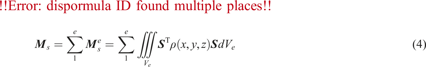
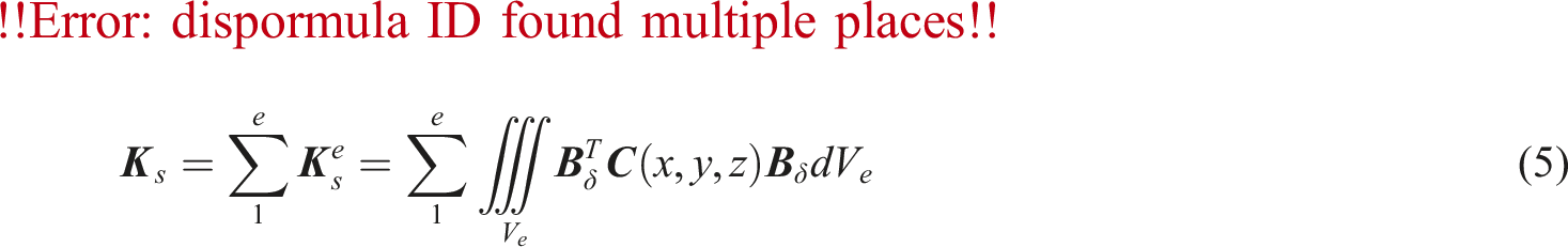
Since the material properties of FGMs vary with the spatial coordinates, the material parameters are related to coordinates, that is, the density ρ (x, y, z) and stiffness coefficients
Based on
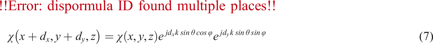
Considering the periodicity of the fluid and acoustic structure, the periodic boundary conditions can be expressed as:
Substituting


Numerical results and analyses
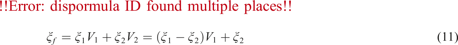
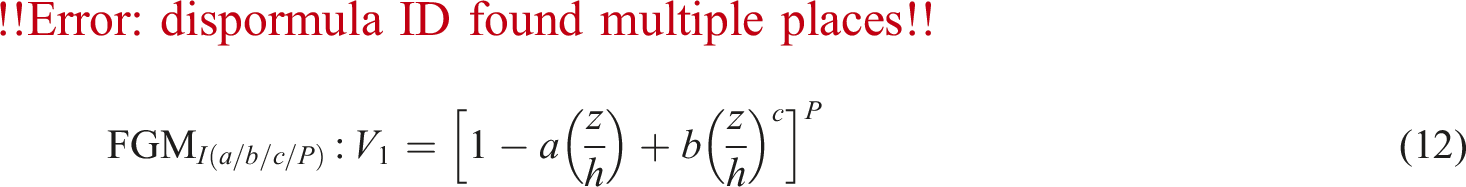
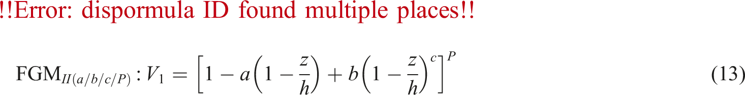
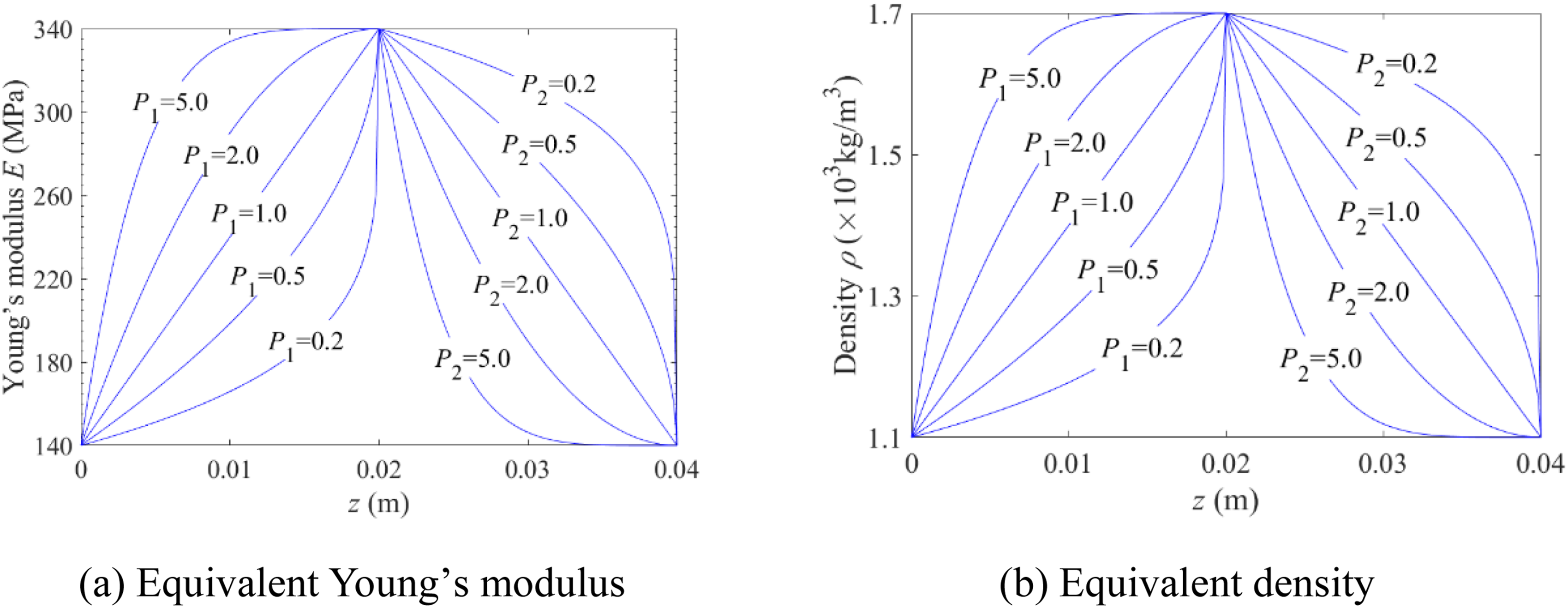
In this paper, the material properties of FGMs present continuously change along the thickness direction. The material parameters of the FGMs can be described by Voigt model30,31:
Acoustic model validation
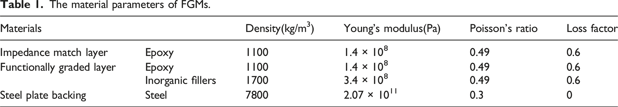
Taking the functional gradient acoustic structure without cavity as an example, AMs-MCS without cavity or resonators as shown in Figure 6 are stratified, and gradient layer 1 and gradient layer 2 are evenly divided into n1 and n2 layers, respectively. The FGMⅠ(a = 1/b = 0/c/P) is used to describe the distribution of the volume fraction of each component in the gradient layer, and the FGMs is synthesized by epoxy and inorganic fillers. The material parameters of each component in the cell of AMs-MCS as are shown in Table 1. The density of water and the velocity of sound are taken as 1000 kg/m3 and 1500 m/s respectively, and the thickness of each layer is hg1 = hg2 = 0.02 m and h3 = 0.005 m, respectively. The gradient distribution of the material properties of the AMs-MCS without cavity or resonator along the thickness direction is shown as Figure 7. The Transfer Matrix Method (TMM) is adopted to verify the correctness of the acoustical calculation model established by G-FEM. Schematic diagram of stratification for AMs-MCS without cavity or resonators. The material parameters of FGMs. The gradient distribution of the material properties of the AMs-MCS without cavity or resonators along the thickness direction.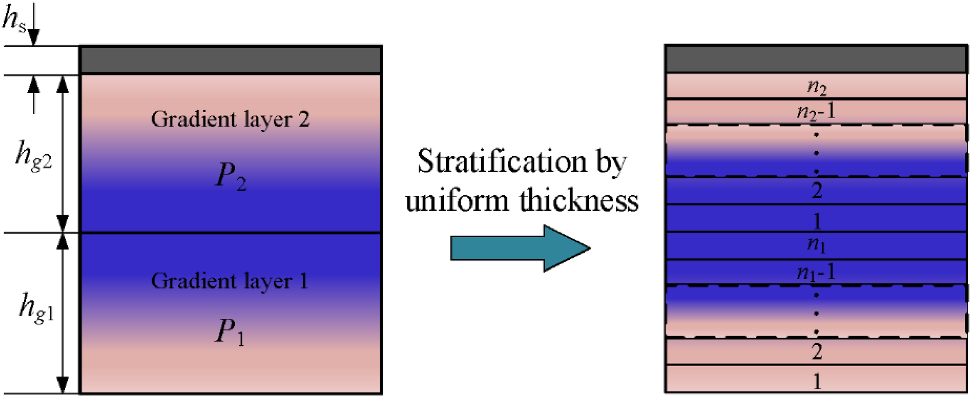
The sound absorption coefficients of AMs-MCS without cavities or resonators are calculated by G-FEM and TMM, respectively. As can be seen from Figure 8, the acoustic coefficients obtained by G-FEM are in good agreement with that obtained by TMM. When the cavity or other filling structure is embedded in the AMs-MCS, only the free boundary or the coupling boundary between different materials is introduced in the AMs-MCS, and the acoustic-structure coupling boundary and the boundary conditions of the fluid domian are not changed, only the element and node information of the structure domain have changed. Therefore, the correctness and effectiveness of the G-FEM calculation model in this paper are not affected, and it is also applicable to FGMs with internal cavities or other fillers. Acoustic coefficients calculated by TMM and G-FEM.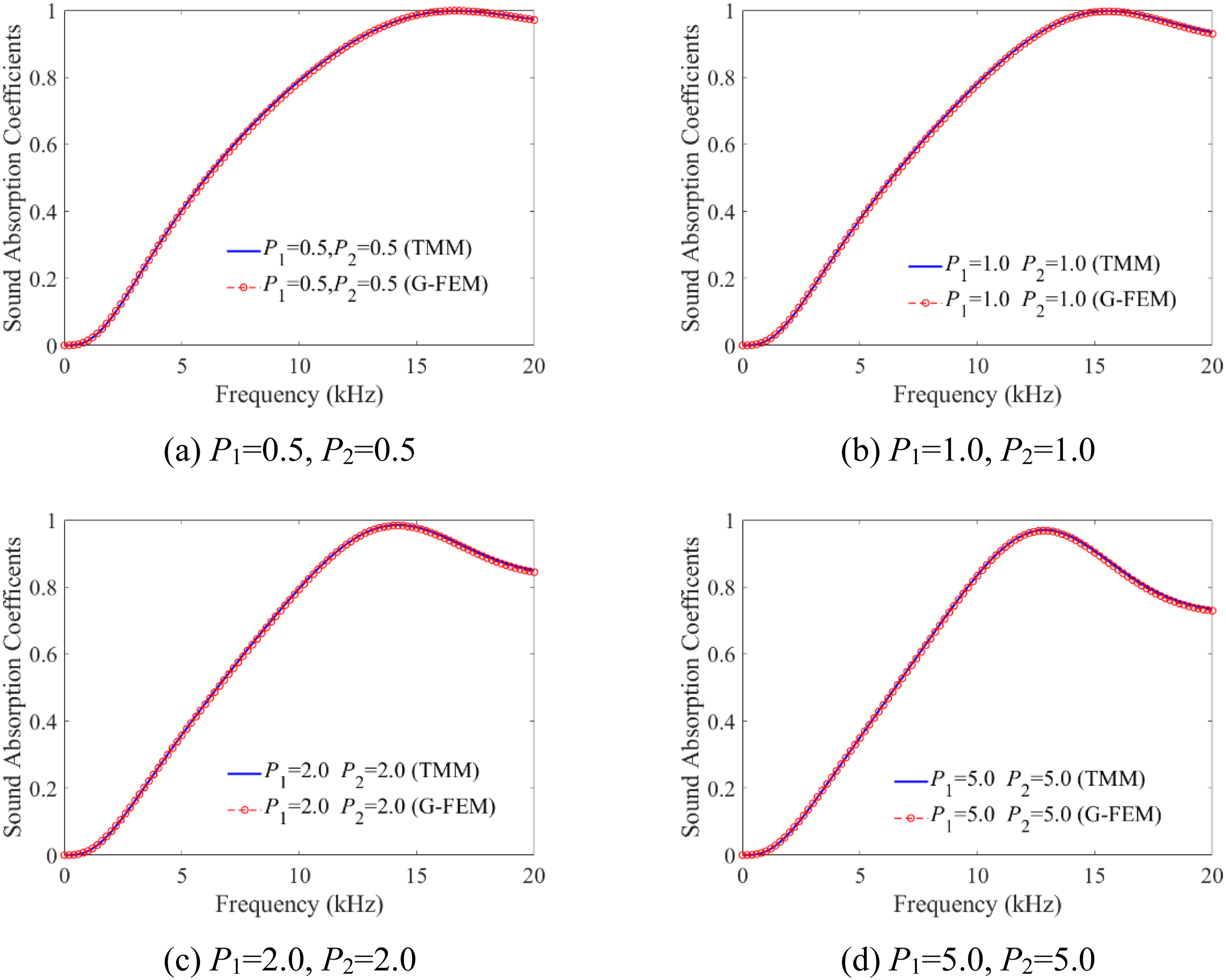
Sound absorption characteristics of the AMs-MCS
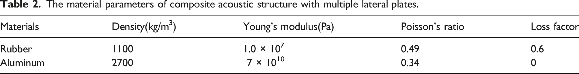
The material parameters of composite acoustic structure with multiple lateral plates.
The comparison of the sound absorption coefficient curves between the composite acoustic structure with multiple lateral plates and the homogeneous acoustic materials without lateral plates is shown in Figure 9. It can be observed that, compared with homogeneous acoustic materials without lateral plates, the sound absorption performance of the composite acoustic structure with multiple lateral plates is almost the same as that of the homogeneous acoustic materials at the low-frequency range and the frequency of the first sound absorption peak. In the middle and high-frequency ranges, the sound absorption coefficients of the composite acoustic structure with multiple lateral plates are obviously greater than that of the homogeneous acoustic materials. Therefore, the sound absorption performance in the middle and high-frequency ranges of the acoustic structure can be improved by embedding the gradient distribution of lateral plates in the homogeneous acoustic materials. Sound absorption coefficient curves of composite acoustic structures with multiple lateral plates and without inserts.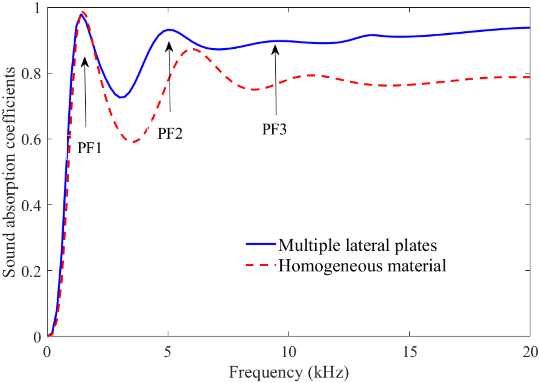
Figure 10 shows structural vibration modes of composite acoustic structures with multiple lateral plates at the frequencies of absorption peaks (PF1, PF2, and PF3). It can be seen that, at the first absorption peak frequency (PF1, f = 1410 Hz), the matrix and steel plate backing of the composite acoustic structures with multiple lateral plates produce bending vibration effect. The vibration energy of the acoustic structure increases successively along the thickness direction, with the minimum at the bottom of the structure (z = 0) and the maximum at the top of the structure (z = h
a
). The structure presents global bending vibration effect. At the second acoustic absorption peak frequency (PF2, f = 5210 Hz), as shown in Figure 10(b), the vibration energy of the structure is mainly concentrated in the matrix. when sound waves propagate inside the structure the sound waves transform into longitudinal and transverse waves due to the scattering effect of the multiple lateral plates on sound waves, thus causing the matrix structure to produce bending vibration effect and enhancing the dissipative effect on sound wave energy. Compared with Figure 10(a), the structure presents single point bending vibration effect when f = 5210 Hz. At the third sound absorption peak frequency (PF3, f = 9210 Hz), as shown in Figure 10(c), the vibration energy of the structure is mainly concentrated in the matrix. The matrix structure also produces bending vibration effect due to the scattering of multiple lateral plates on sound waves. Compared with Figure 10(b), the structure presents two-point bending vibration effect. Structural vibration modes of composite acoustic structures with multiple lateral plates at the frequencies of absorption peaks.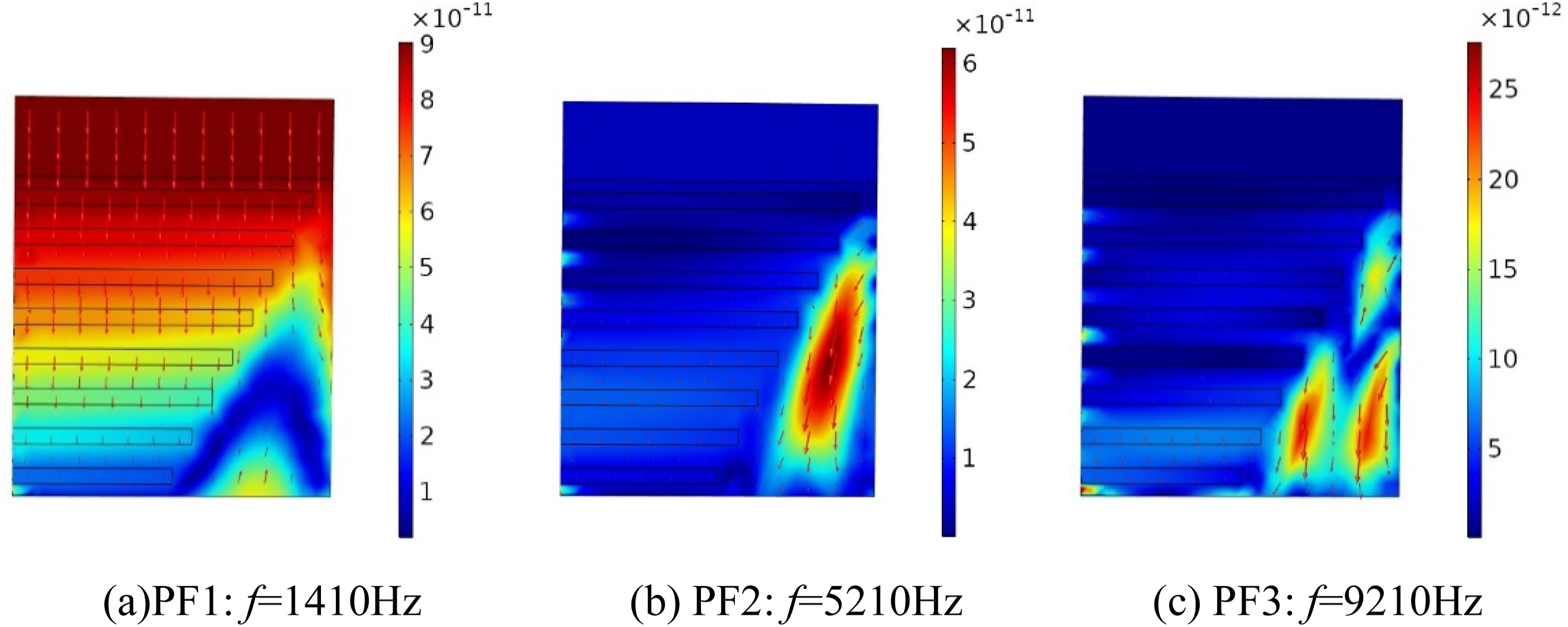
Based on the sound absorption performance of composite acoustic structures with multiple lateral plates studied above, the underwater sound absorption performance of the AMs-MCS is studied below, considering the coupling effect between each substructure as shown in Figure 3.
The cell thickness of substructure Ⅰ–Ⅳ is h1 = h2 = h3 = h4 = 0.04 m, and the lattice constants of substructure along x and y directions are a1 = a2 = a3 = a4 = 0.04 m, respectively. The radii of spherical resonators and coating layers in substructure Ⅰ are r1 = 0.018 m, r2 = 0.0171 m, r3 = 0.0157 m, r4 = 0.0145 m, r5 = 0.0125 m and r6 = 0.0104 m, respectively. The radii of spherical resonator and coating layer in substructure II are r7 = 0.018 m and r8 = 0.015 m, respectively. The radius and height of the cylindrical cavity in substructure Ⅲ are rc1 = 0.009 m, rc2 = 0.0127 m, rc3 = 0.0156 m, rc4 = 0.018 m, hc1 = hc2 = hc3 = hc4 = 0.008 m, respectively. In substructure Ⅳ, the thickness of lateral plate is t
p
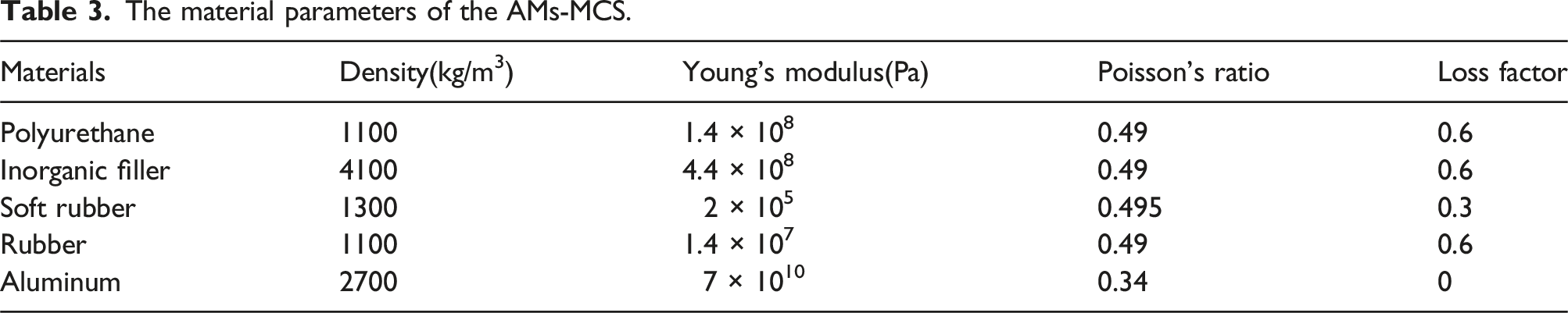
= .002 m, the number of lateral plates n is 6, and the initial width is b1 = 0.02 m. Thickness of steel plate backing hs = 0.01 m. The functional gradient layers in the substructure I-III are synthesized by polyurethane and inorganic filler, and the gradient distribution of the material properties of the structure along the thickness direction. is shown in Figure 11. The coating layer and spherical resonator in substructure Ⅰ and Ⅱ are made of soft rubber and steel respectively, the matrix material of substructure Ⅳ is rubber, the lateral plate structure is aluminum plate. The material parameters of each component of the AMs-MCS are shown in Table 3. Moreover, the density of water is 1000 kg/m3, the sound peed is 1500 m/s, the length of each element is less than 1/4 of the shear wave wavelength of the respective material, and the calculation results calculated by acoustic calculation model established in The gradient distribution of the material properties of the structure along the thickness direction. The material parameters of the AMs-MCS.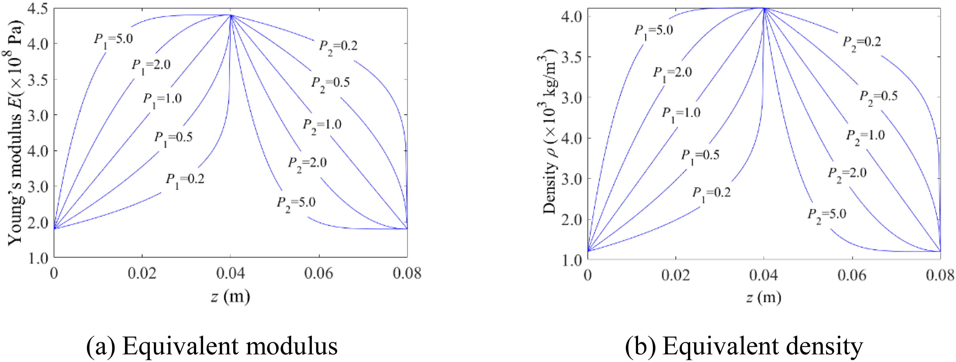
The sound absorption coefficient curves of the AMs-MCS under various gradient indices are shown in Figure 12. It can be seen that, with the change of the gradient indices of the functional gradient materials in substructure Ⅰ and Ⅱ, the sound absorption performance of the AMs-MCS in the low-frequency range has almost no change. The absorption coefficients of the high-frequency range of the compound acoustic structure coupled with multiple structures are increased, which effectively broadens effective sound absorption band of the acoustic structure. When P1 = 5.0 and P2 = 5.0, the first sound absorption peak frequency (PF1) of the AMs-MCS is 510 Hz, and the sound absorption coefficient is 0.81 at PF1. In the frequency range of 510Hz-10 kHz, the sound absorption coefficients of the AMs-MCS are above 0.8, and the average sound absorption coefficient reaches 0.893. Sound absorption coefficients of the AMs-MCS under various gradient indexes.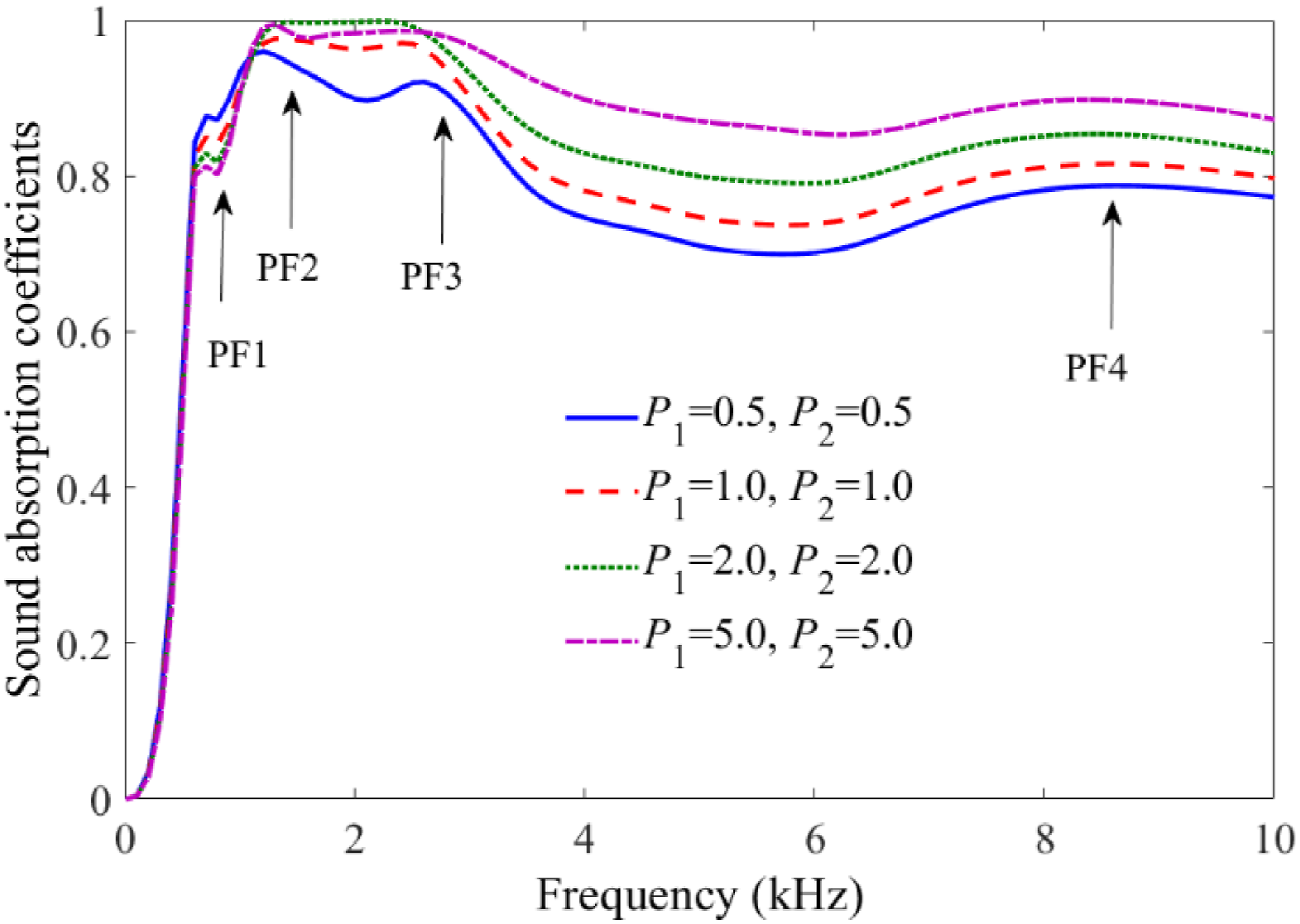
When the gradient index of the functionally graded material in substructure Ⅰ and Ⅱ is P1 = 5.0 and P2 = 5.0, respectively, Figure 13 shows the vibration modes of the AMs-MCS at frequencies of absorption peaks. It can be seen that from Figure 13(a), the vibration energy of the structure is mainly concentrated in the resonators of the substructures I and II when f = 510 Hz at the first acoustic peak frequency (PF1). The regulation effect of the AMs-MCS on the sound wave is mainly through the local resonance of the resonators and the coupling resonance effect between the resonators. At the second absorption peak frequency (PF2, f = 1310 Hz), as shown in Figure 13(b), the vibration energy of the acoustic structure is mainly concentrated in the gradient cavity of substructure Ⅲ and the coating layer. The regulation effect of the AMs-MCS on the sound wave is mainly through the cavity resonance effect and the bending vibration effect generated by the thin layer between the gradient cavity, which makes the longitudinal wave transforms into transverse wave and dissipates the energy of the sound wave through the viscosity of the material itself. At the third absorption peak frequency (PF3, f = 2310 Hz), as shown in Figure 13(c), the vibration energy of the structure is mainly concentrated in the matrix structure of substructure I. The AMs-MCS exerts an effect on the sound wave mainly through the bending vibration generated by the matrix of substructure I, resulting in the transformation of the sound wave into transverse wave. At the fourth absorption peak frequency (PF4, f = 8310 Hz), as shown in Figure 13(d), the vibration energy is mainly concentrated in the matrix of substructure Ⅳ. The effect of the AMs-MCS on the sound wave is mainly through the multiple scattering effect of the lateral plates in substructure Ⅳ on the sound wave, and the acoustic wave transformation occurs under the scattering effect of the lateral plates. The bending vibration effect of the matrix enhances the energy dissipation of sound waves in viscoelastic materials. Therefore, the AMs-MCS has a variety of regulation mechanisms for sound waves of different wavelengths, so that the low frequency and broadband strong sound absorption can be achieved. Structural vibration modes of the AMs-MCS at frequencies of absorption peaks.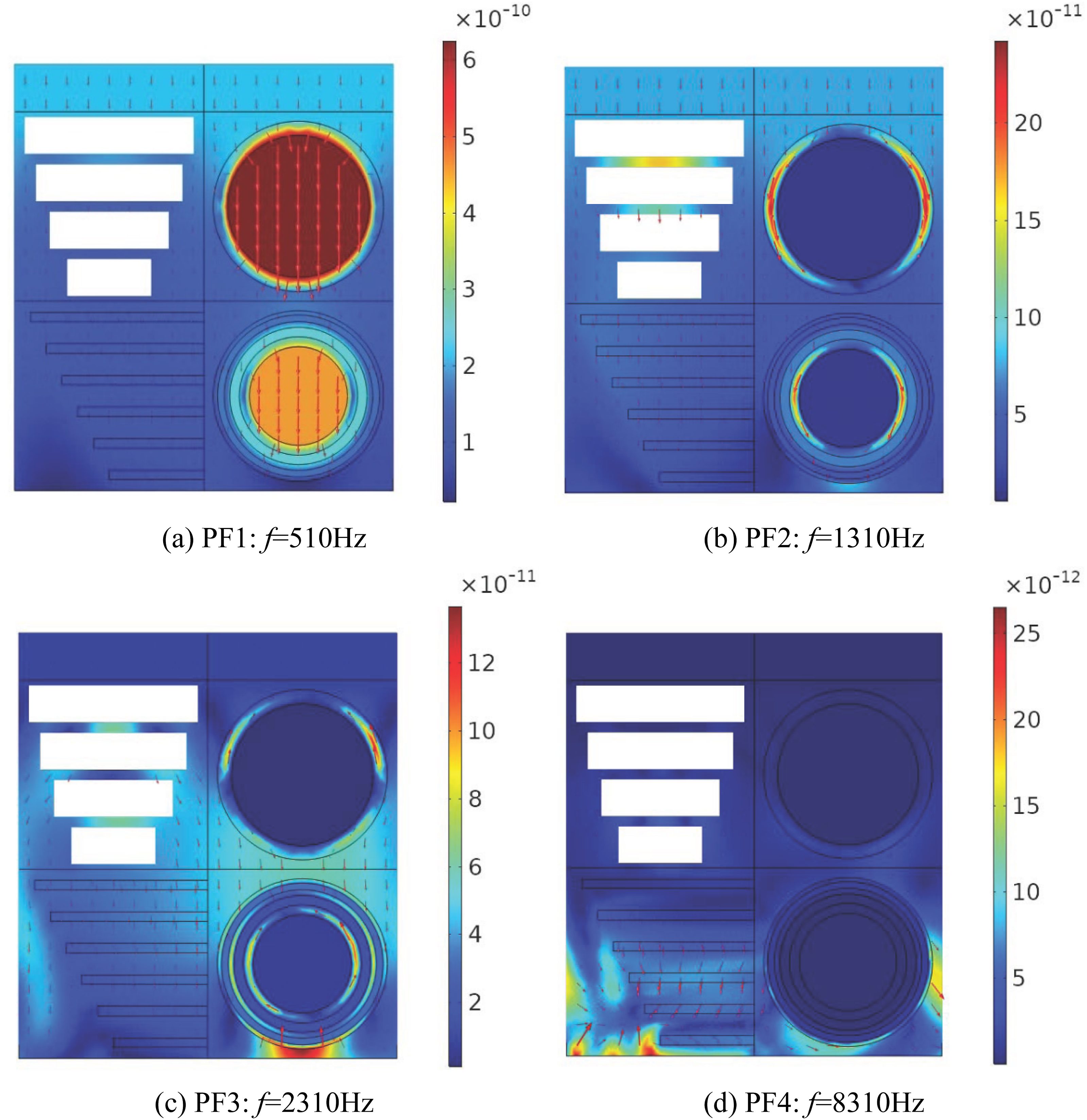
The regulation of sound absorption characteristics
The following studies are carried out on the effects of material parameters, structural parameters and gradient forms on the sound absorption characteristics of the AMs-MCS. The main material parameters include Young’s modulus, density and gradient forms of FGMs, and the structural parameters mainly include resonator distribution and coupling forms between substructures.
The influence of the modulus and density of inorganic fillers on the sound absorption coefficient of the AMs-MCS is illustrated in Figures 14 and 15, taking the examples of P1 = 1.0, P2 = 1.0 and P1 = 5.0, P2 = 5.0. It can be observed that under a constant gradient index, an increase in the modulus of the inorganic filler has almost no effect on the low-frequency range absorption performance of the AMs-MCS. There is no change in the frequency of the first absorption peak while the second and third peaks shift towards higher frequencies. Furthermore, variations in the modulus of the inorganic filler have minimal impact on high-frequency range absorption performance of the AMs-MCS. Under a constant gradient index condition, an increase in density for inorganic fillers also has negligible effects on low-frequency range absorption performance of the AMs-MCS. There is no change to frequencies of the first and second absorption peaks while the third peak shifts towards lower frequencies. Additionally, as density increases for inorganic fillers, so does the absorption coefficient within high-frequency range for the AMs-MCS. The influence of the modulus of inorganic fillers on the sound absorption coefficient of the AMs-MCS. The influence of the density of inorganic fillers on the sound absorption coefficient of the AMs-MCS.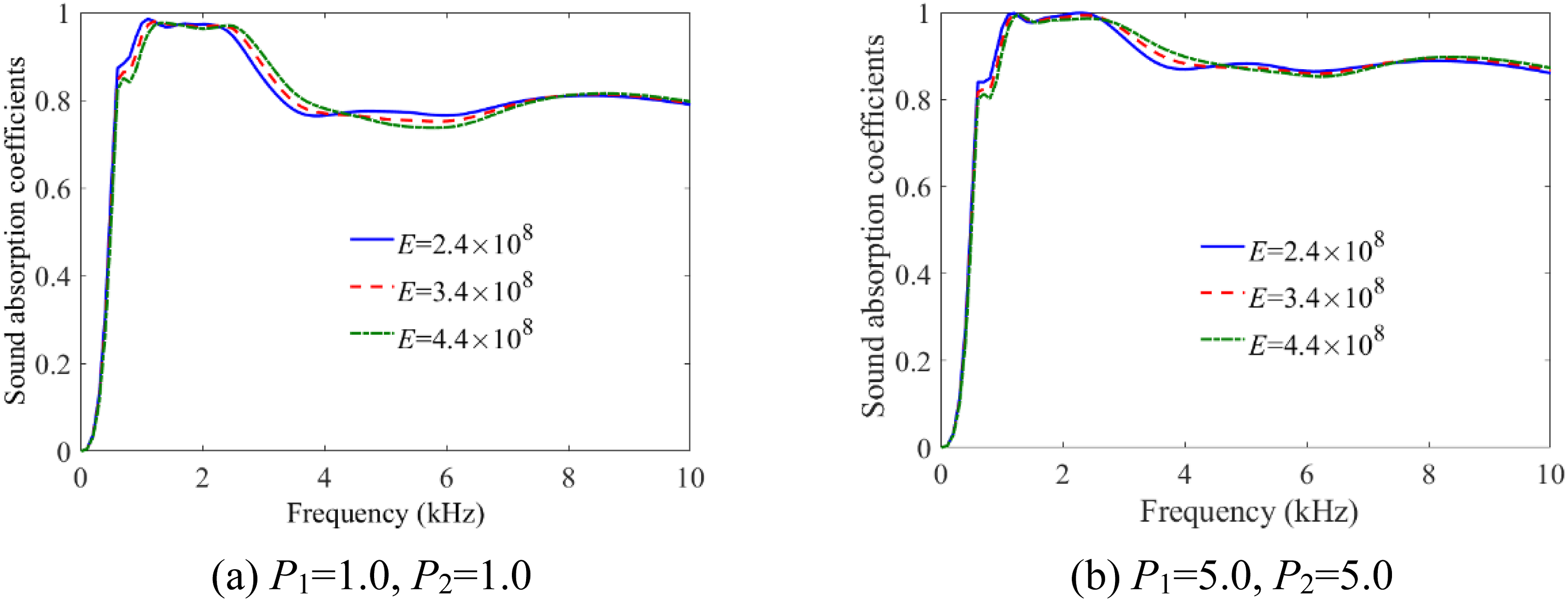
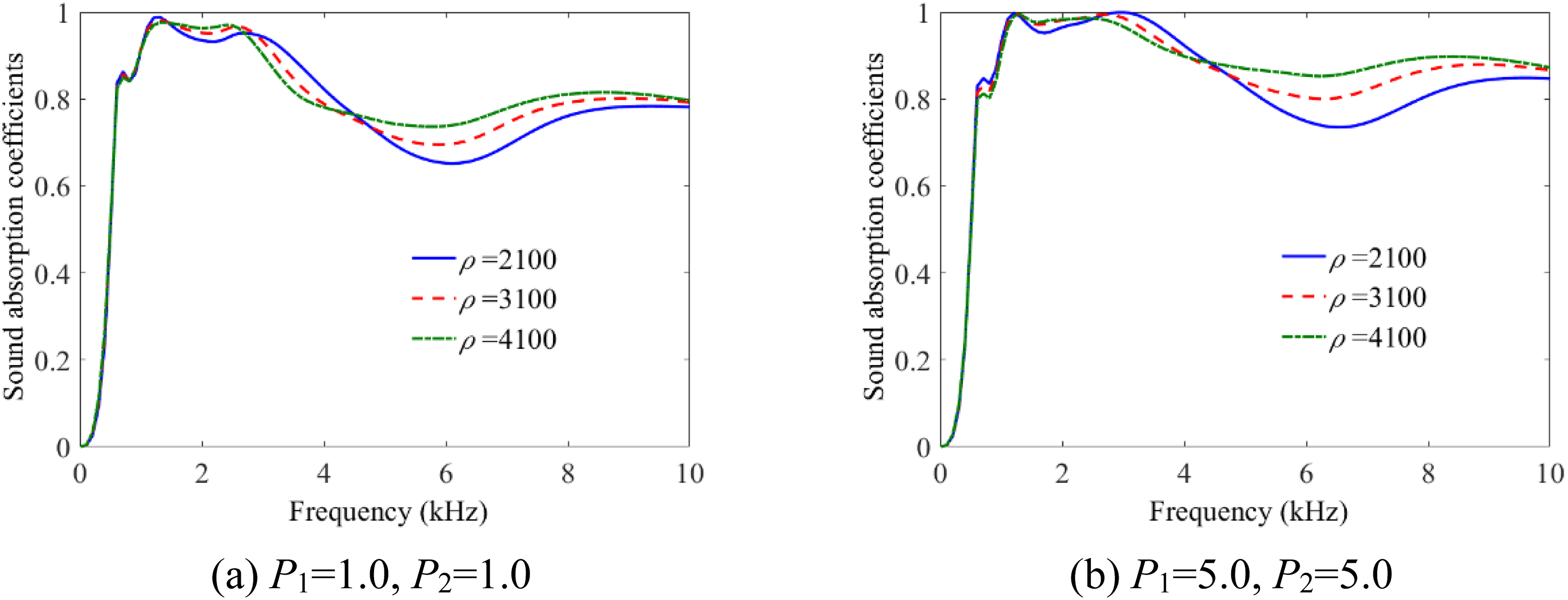
Based on the structural vibration mode diagram of the AMs-MCS at the absorption peak frequency presented in Figure 13, it is evident that at the first absorption peak frequency, the structural vibration energy primarily concentrates in the resonators. The effect of the AMs-MCS on sound waves mainly arises from internal local resonance and coupling resonance between multi-resonator. Changes in Young’s modulus and density of inorganic fillers have minimal impact on sound absorption performance within the low-frequency range and at the first peak frequency of the AMs-MCS. At the second sound absorption peak, this effect is predominantly through cavity resonance and bending vibration generated by thin layers between gradient cavities. Consequently, an increase in modulus of inorganic filler shifts to higher frequencies for the second sound absorption peak of the AMs-MCS. For the third sound absorption peak, its effect on sound waves mainly stems from bending vibration generated by matrix of substructure I. Thus, with increased modulus of inorganic filler, the third sound absorption peak also shifts to higher frequencies while shifting to lower frequencies for the AMs-MCS. Furthermore, increasing density of inorganic fillers enhances acoustic impedance of matrix structures which augments attenuation of sound wave energy and increases sound absorption coefficient within high-frequency range for composite acoustic structures.
The effects of the gradient indices P1 and P2 of FGMs in the substructures on the sound absorption coefficients of the AMs-MCS are respectively studied. Under the condition of a constant gradient index P2, the influence of gradient index P1 of substructure I on the absorption coefficient of the AMs-MCS is shown in Figure 16. It can be found that, as the gradient index P1 of the matrix material in substructure I increases, the low-frequency range absorption performance of the AMs-MCS is not affected, and the frequency of the first absorption peak remains almost unchanged. However, the peak value of the first absorption peak decreases, and the second and third absorption peaks both move to higher frequencies. The absorption coefficient of AMs-MCS in the high-frequency range increases; therefore, increasing gradient index P1 can effectively improve the high-frequency range absorption performance of the AMs-MCS. The effect of gradient index P1 on the sound absorption coefficients of the AMs-MCS.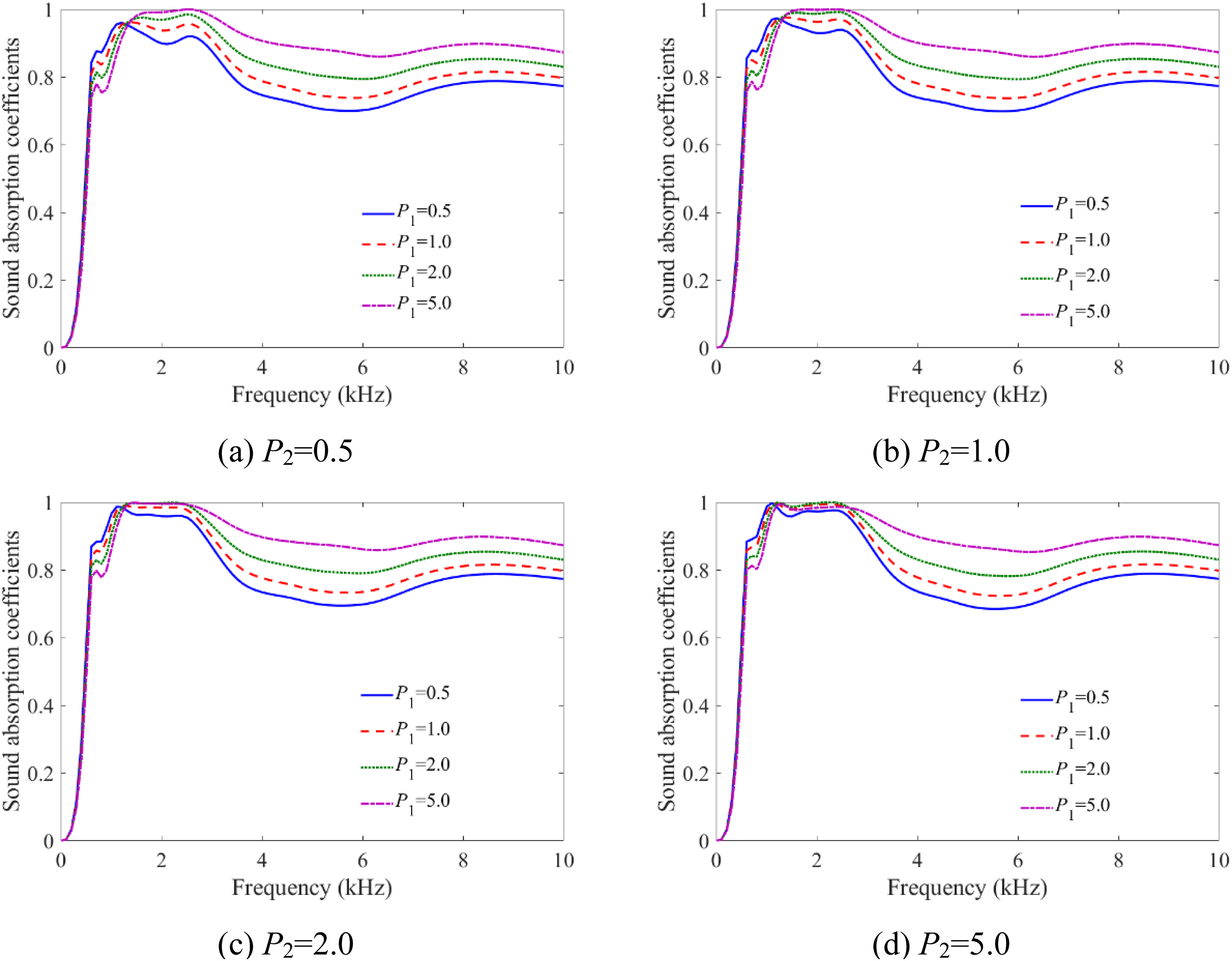
Under the condition of a constant gradient index P1, the influence of gradient index P2 of substructure II on sound absorption coefficients of the AMs-MCS is shown in Figure 17. It can be seen that, the low-frequency range absorption performance of the AMs-MCS is not affected by the increase of gradient index P2, and the first absorption peak frequency remains almost unchanged. However, the peak value of the first absorption peak increases, and the second and third absorption peaks move to lower frequencies. The absorption coefficient of the AMs-MCS remains unchanged in high-frequency range. The effect of gradient index P2 on the sound absorption coefficients of the AMs-MCS.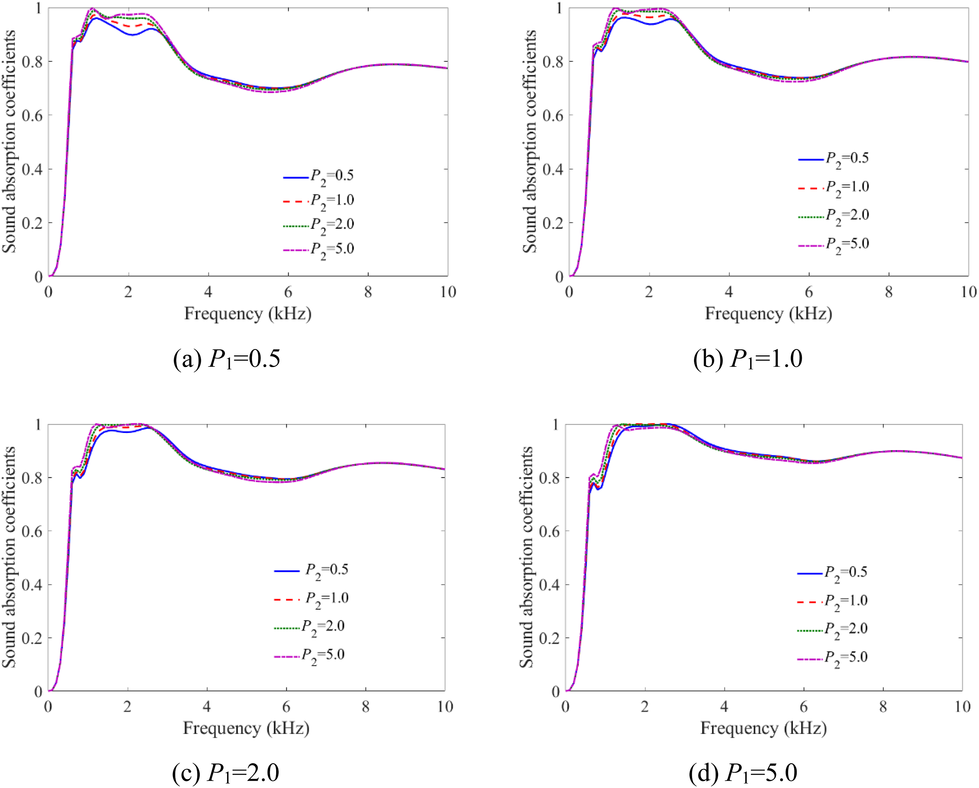
From the structural vibration modes of the AMs-MCS shown in Figure 13, it can be seen that at the frequency of the first absorption peak, the regulation effect of the AMs-MCS on sound wave on is mainly through local resonance and coupled resonance of multi-resonator. Therefore, the change of the gradient index of the FGMs has little effect on the low-frequency range of the absorption performance and the first absorption peak frequency of the AMs-MCS. At the frequencies of the second and third absorption peaks, as P1 increases, the equivalent modulus of the matrix of substructure I increases, so both the second and third absorption peaks shift to higher frequencies. Furthermore, the increase of the equivalent modulus of the matrix material makes the equivalent impedance of the matrix material increase, so the absorption coefficient in the high-frequency range of the AMs-MC increases. As the gradient index P2 increases, the equivalent modulus of the matrix material in substructures II and III decreases, resulting in a decrease in the effective stiffness of the matrix. Therefore, the increase in gradient index P2 causes the second and third absorption peaks of the AMs-MCS to shift towards lower frequencies. In the high-frequency range, the regulation of the AMs-MCS on sound waves mainly depends on the acoustic scattering effect of substructure IV, therefore, the change in gradient index P2 has little effect on the high-frequency range absorption performance of the AMs-MCS. In addition, the shift of the second absorption peak of the AMs-MCS to lower frequencies enhances the coupling effect between the first and second absorption peaks, lifting the peak value of the first absorption peak and resulting in an increase in the peak value of the first absorption peak.
Subsequently, an analysis of the effect of the vibrator distribution forms in substructures I and II on sound absorption coefficient of the AMs-MCS is conducted. Figure 18 gives examples of the AMs-MCS with different types of resonator distributions. Cross-sectional view of a unit cell of the AMs-MCS with different resonator distribution forms on xoz plane.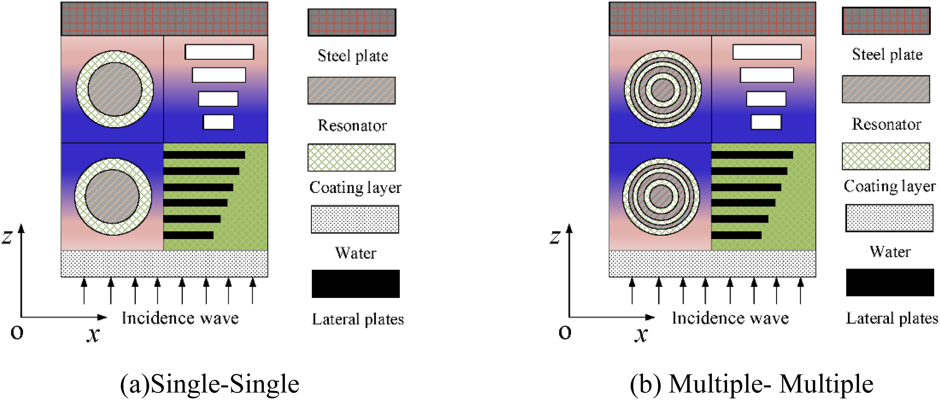
It can be seen from Figure 18(a) that both substructures I and II contain single resonators, named “Single-Single,” while from Figure 18(b) that both substructures I and II contain multiple resonators, named “Multiple-Multiple.” The filling rates of the resonators in both substructures are the same as those in the “Multiple -Single” distribution shown in Figure 5. When the gradient indices P1 = 5.0 and P2 = 5.0 for substructures I and II respectively, the absorption coefficient curves for the AMs-MCS with different types of resonator distributions are shown in Figure 19. It can be found that, the first absorption peak frequency of the composite acoustic structure increases from 510 Hz to 810 Hz when the “Multiple-Multiple” form is used in substructure II compared to the “Multiple-Single.” The second and third absorption peaks remain unchanged, and the absorption performance in high-frequency range is almost unchanged. In contrast, when the single resonator is used in substructure I, the first absorption peak frequency of the AMs-MCS remains basically unchanged, the peak value of the first absorption peak increases, the third absorption peak shifts slightly towards lower frequencies, and the absorption coefficients in the mid-frequency range decrease. The effect of resonator distribution forms on sound absorption coefficients of the AMs-MCS.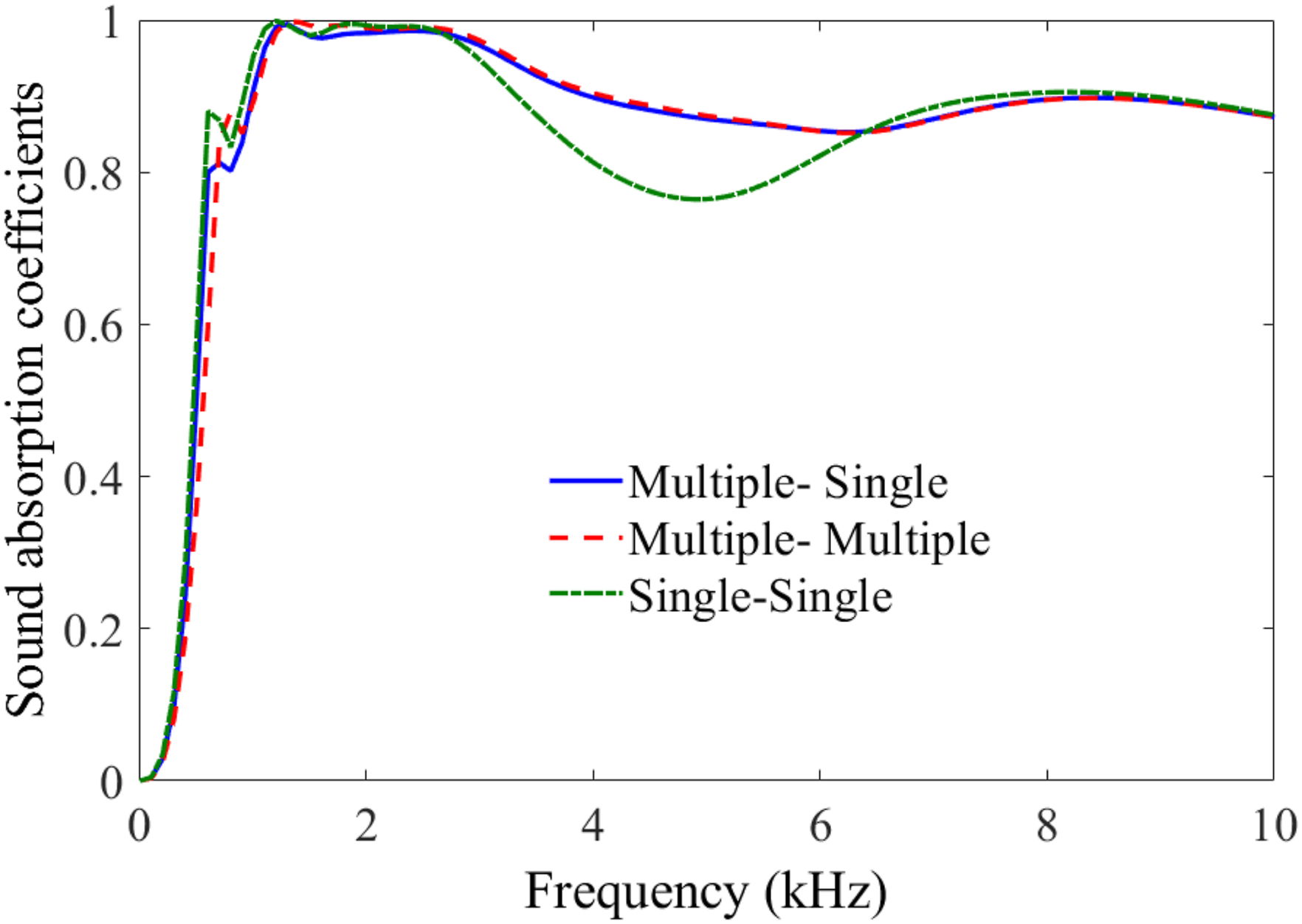
Based on the structural vibration modes of the AMs-MCS shown in Figure 13, it can be seen that, at frequency of the first absorption peak, the sound waves are regulated through local resonance and coupling resonance effect inside of the AMs-MCS. Under the condition of the same filling rate of resonators, the mass of the single resonator and the thickness of the coating layer decrease if the multi-resonator is adopted in substructure II, so the frequency of the first absorption peak of the AMs-MCS is reduced. At the frequency of the third absorption peak, the sound waves are regulated through the bending vibration effect in substructure I. When the single resonator is embedded inside of substructure, the bending vibration mode of the substructure is changed due to the change in distribution of the coating layers and resonators, which causes the third absorption peak to shift slightly to lower frequencies and the absorption coefficients in the mid-frequency range of the AMs-MCS to decrease.
The effect of the different coupling modes between substructures on the sound absorption coefficient of the AMs-MCS is studied below. The coupling mode between the substructures in Figure 5 is defined as coupling form 1#, and Figure 20 shows three other different coupling modes, namely, coupling forms 2#, 3#, and 4#, respectively. In these coupling modes, the material parameters and geometric parameters of the substructures remain unchanged and are the same as those in Figure 5. Figure 21 gives the absorption coefficient curves of the AMs-MCS under different coupling forms. It can be seen that, the sound absorption coefficients of the AMs-MCS are basically the same under coupling form 1# and coupling form 2#. Different coupling modes between substructures of the AMs-MCS. The effect of coupling of substructures on sound absorption coefficients of the AMs-MCS.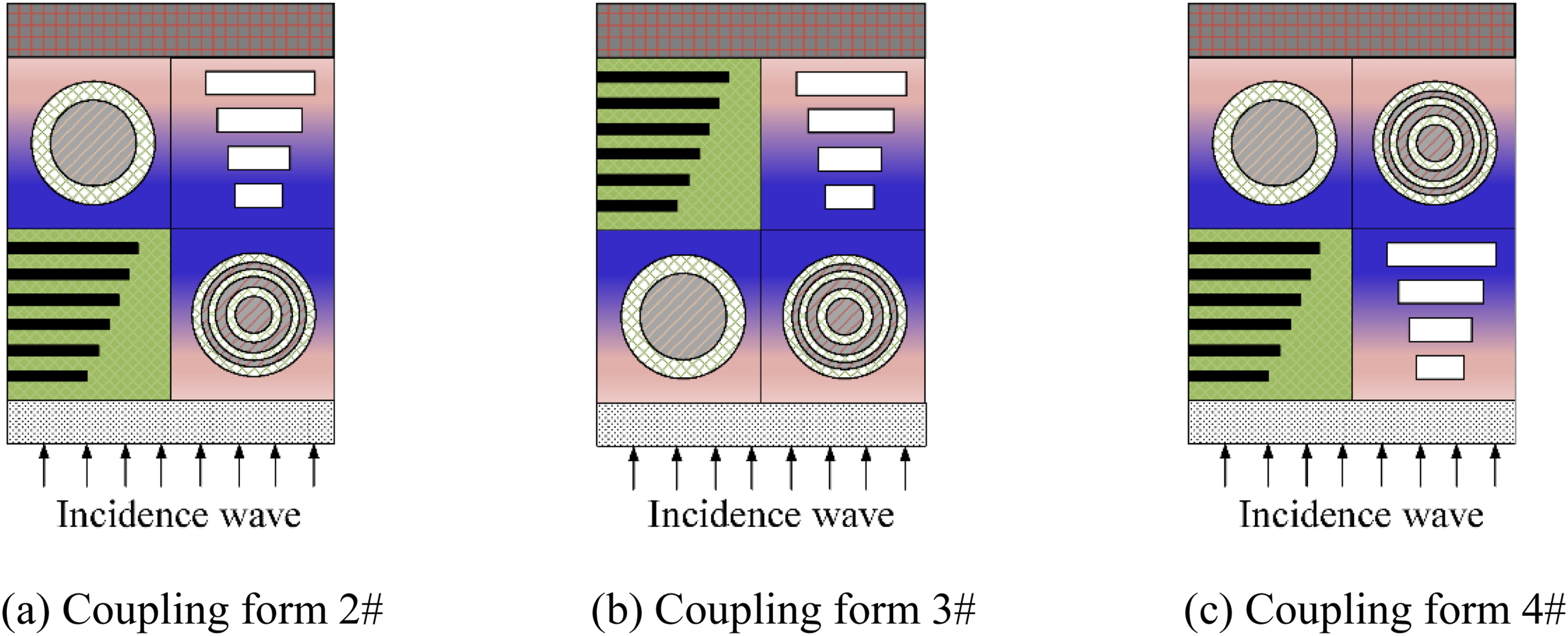
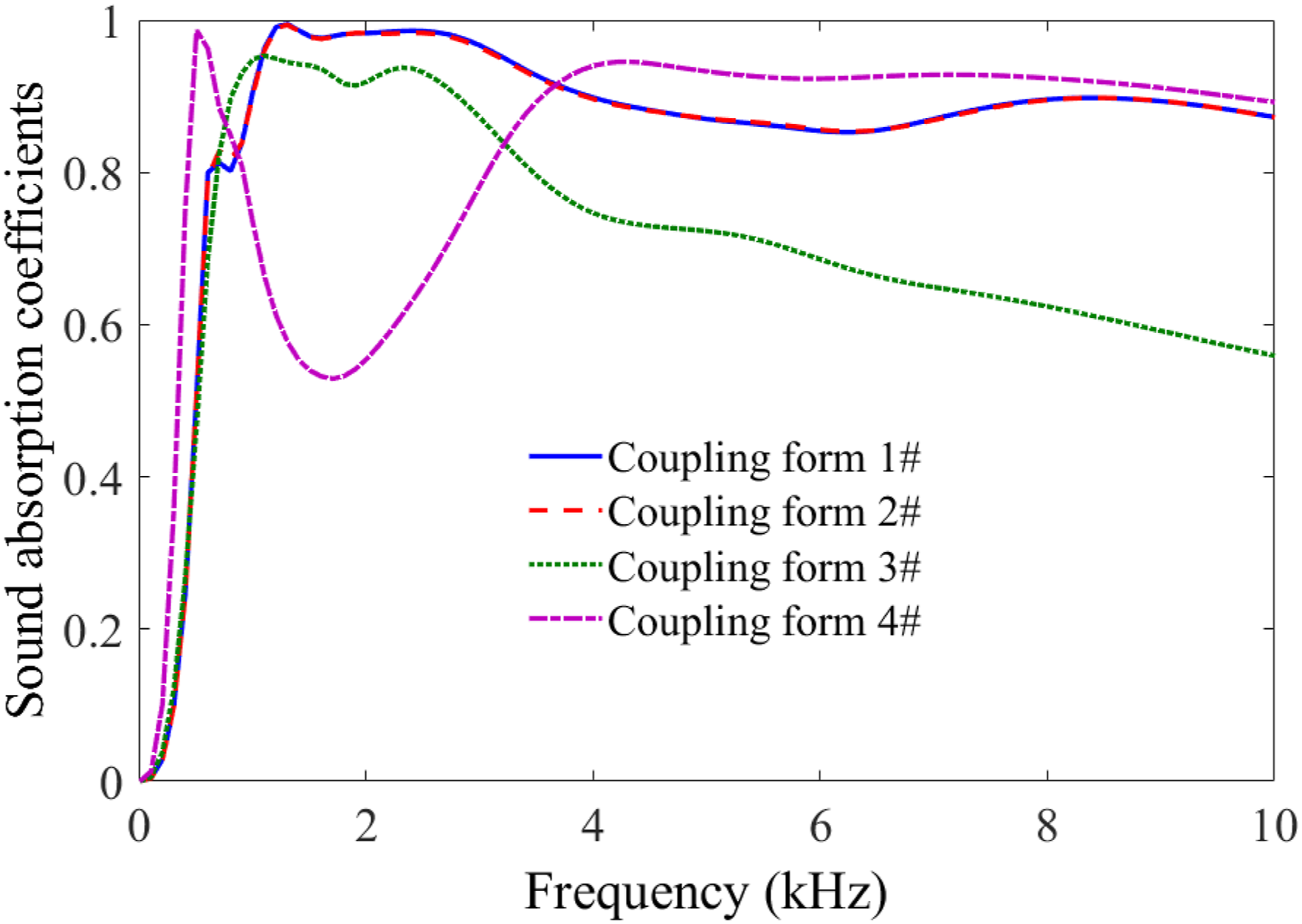
The sound absorption coefficient of the AMs-MCS remains consistent when operating under coupling form 1# and coupling form 2#. Altering the positional relationship between substructure I and IV has minimal impact on the sound absorption performance of the AMs-MCS. In comparison to coupling form 1#, adopting coupling form 3# between the substructures results in a nearly unchanged sound absorption performance in the low-frequency range, while reducing the sound absorption coefficient in the middle and high-frequency ranges. Similarly, employing coupling form 4# leads to an increase in the sound absorption coefficient at both low and high frequencies but decreases it in the mid-frequency range significantly, creating a noticeable “sound absorption valley.”
When using coupling form 2# instead of coupling form 1#, which only changes the positional relationship between substructures I and IV, there is no effect on sound wave regulation mechanism for each substructure within the AMs-MCS. Furthermore, when applying coupling modes 3# or 4#, distinct effects are observed due to variations in internal board placement and enhanced vibrational dissipation. Compared with coupling form 1#, when coupling form 2# is adopted between substructures, only the position relationship between substructures Ⅰ and Ⅳ is changed, which has no effect on sound wave regulation mechanism for each substructure inside AMs-MCS. Therefore, the sound absorption coefficient of the AMs-MCS is basically the same under coupling form 1# and coupling form 2#.
When the coupling form 3# is adopted between the substructures, the scattering effect of lateral plates of the substructure Ⅳ on the sound wave is weakened in the high-frequency range, and the regulation of the AMs-MCS on the sound wave is mainly through the bending vibration effect generated by the matrix of the substructures Ⅰ and Ⅱ. Therefore, the sound absorption coefficient of the AMs-MCS in the high-frequency range decreases. In contrast, when the coupling form 4# is adopted between the substructures, the coupling effect of the resonator in substructures Ⅰ and Ⅱ is enhanced, so that the dissipation effect of the AMs-MCS on the low-frequency acoustic wave is enhanced. The coupling effect of the composite gradient structure of substructure Ⅲ and the lateral plates of substructure Ⅳ enhances the dissipation effect of sound waves in high-frequency range. When the coupling mode 4# is adopted between the substructures, the sound absorption coefficients of the AMs-MCS increase in the low-frequency range, and the sound absorption coefficients in the high-frequency range also increase. However, the use of coupling form 4# will weaken the regulation effect of the AMs-MCS on sound wave in the mid-frequency range, resulting in an obvious absorption valley in the absorption coefficient curve of the AMs-MCS in the mid-frequency range.
By comprehensively comparing the coupling modes between substructures and their impact on the sound absorption performance of the AMs-MCS, it can be seen that the coupling effect between resonators in coupling mode 4# is significantly stronger than that in coupling modes 1# or 2#. Therefore, the coefficient in the low-frequency range of the AMs-MCS with coupling mode 4# is greater than that with coupling mode 1# or 2#. Therefore, the optimal deployment coupling mode for substructures with resonators is to use “parallel” connection between oscillators and embed them in gradient layer 2. Moreover, by comparing coupling modes 1#, 2#, and 3#, it can be seen that the scattering effect of lateral plates on sound waves in the AMs-MCS with coupling mode 1# or 2# is significantly stronger than that in coupling mode 3#. Therefore, the coefficient in the high-frequency range of the AMs-MCS with coupling mode 3# is lower than that with coupling mode 1# or 2#. Therefore, the optimal deployment coupling mode for substructures with lateral plates or cavities is to use “parallel” connection and embed them in gradient layer 1.
When the optimal coupling mode is used simultaneously in gradient layers 1 and 2, although the AMs-MCS achieves optimal sound absorption coefficients in both low and high-frequency ranges, the weakened coupling effect of absorption peaks between the low and high-frequency bands reduces the sound absorption coefficients in the mid-frequency range, creating a noticeable “sound absorption valley.” Therefore, in order to ensure that the effective sound absorption frequency band of the AMs-MCS can cover the entire frequency band, including low-, mid-, and high-frequency bands, coupling method 1 or 2 is the optimal coupling method between substructures.
Conclusions
In this paper, an AMs-MCS based on multiple structure coupling is designed by combining multi-resonator coupling resonance structure, gradient lateral plates and functional gradient structure. The underwater sound absorption characteristics and regulation mechanism for sound wave inside the AMs-MCS are systematically studied, and the regulation laws of each substructure on the sound absorption performance of the AMs-MCS are explored. Based on the numerical results in this paper, the following conclusions can be drawn. (1) Compared with the homogeneous acoustic materials, the sound absorption coefficient of the composite acoustic structure with multiple lateral plates in the middle and high-frequency range is significantly greater than that of the homogeneous acoustic structure. Therefore, the effective sound absorption band of the acoustic structure can be broadened by embedding the gradient distribution of multiple lateral plates inside the homogeneous acoustic structure. (2) The AMs-MCS proposed in this paper has a variety of regulation mechanisms for sound waves of different wavelengths, and the sound absorption coefficients of AMs-MCS are greater than 0.8 at each frequency point in the frequency range of 500Hz-10 kHz, and the average sound absorption coefficient reaches 0.893, so that the low-frequency broadband sound absorption performance can be achieved. (3) The AMs-MCS designed in this paper can provide theoretical basis and technical support for the development and design of anechoic coating for underwater low-frequency and broadband sound absorption.
Footnotes
Declaration of conflicting interests
The author(s) declared no potential conflicts of interest with respect to the research, authorship, and/or publication of this article.
Funding
The author(s) disclosed receipt of the following financial support for the research, authorship, and/or publication of this article: This research is supported by the National Natural Science Foundation of China (Grant Nos. U2141244 and 52225109), and Jiangsu Province Natural Science Foundation (Grant No. BK20240320).