
Abstract
As an applicable noise attenuator, Helmholtz resonator is mainly used to dampen acoustic noise at low- and medium-frequency ranges. It is typically implemented in combustion-engines and gas turbines to dampen thermoacoustic instabilities. However, it has a narrow effective frequency range and does not work effectively at off-design conditions. In this work, we consider a modified structured Helmholtz resonator (HR) at its neck by applying a rigid baffle in order to maximize its’ noise damping effect and to broaden its frequency bands. The resonator is attached to a cylindrical duct/pipe in presence of a mean flow (grazing flow), aiming to simulate the practical engines flow configuration. For this, a two-dimensional frequency domain numerical model is developed by using COMSOL V5.3. The numerical simulations are carried out by solving the linearized Navier–Stokes equation in frequency domain with low computational cost and time. In order to obtain an optimum design in terms of the maximum noise damping performances, 10 new different configurations/designs are proposed. The effects of 1) the single baffle attached to the upstream or downstream sidewall of the neck ends, that is, Design A, B, C, and D or double baffles, that is, Design E, F, G, and H), 2) the baffle implementation location, 3) the length of the rigid baffle, and 4) the grazing flow low Mach number are evaluated and compared. It is found that Design C is associated with improved TL by 50% and decreased resonant frequency by 20% comparing with the conventional HR. The present preliminary study shows that Design C is the better design. Further experimental and optimization researches are needed to sheds light on the optimum design of a Helmholtz resonator with neck structure being modified, as there is a low Mach number grazing flow.
Introduction
Helmholtz resonators are widely implemented as an aeroacoustics damper on aero-engines and gas turbines. In propulsion systems, the resonators are applied to mitigate combustion instability.1-2 The limit cycle noise is produced, when the combustion instability occurs. Such instability strongly affects the service life of the engines, which results in a large amount of financial and material losses. The main sound absorption mechanisms of Helmholtz resonator include thermos-viscous and vortex shedding effects. As an industry muffler, the Helmholtz resonators are implemented on automobiles to increase the noise transmission losses. Conventional Helmholtz resonators have only one resonance peak, and are effective over narrow frequency bands. Therefore, in order to obtain more resonance peaks and to broaden the effective frequency ranges, the conventional Helmholtz resonators need to be optimized. This could be achieved by modifying its structure such as extended neck. 3 Extensive studies and analyses have been performed on Helmholtz resonators, as there is a grazing and/or bias (cooling) flow. Selamet et al. 3 studied the acoustic performance of a concentric circle Helmholtz resonator with an extended neck via theoretical, numerical, and experimental methods in the absence of a mean grazing flow. It is found that the shape and the axial length of the extended neck are strongly affecting the resonance frequency and the transmission losses. They also studied the effect of the perforation orifices on the extended neck (i.e., the porosity) on the resonator’s resonant frequency without varying its cavity volume. Zhao et al. 4 numerically examined the role of the mean grazing flow on a number of Helmholtz resonators with various angled extended necks. It is found that Helmholtz resonator with an extended neck have different maximum transmission losses, when the grazing flow Ma is Ma>0.05. Approximately 20% of the resonance frequency variation was observed.
Optimizing the resonator neck may increase or decrease the transmission losses by 5–15 dB over a wide frequency range. Wu et al. 5 numerically investigated aeroacoustics damping performance of a Helmholtz resonator in the presence of a joint bias-grazing flow. They showed that when a joint bias-grazing flow is present, the effects of the cooling/bias flow may give rise to a transmission loss peak being reduced around 5 dB. Lu et al.6,12 numerically examined the asymmetric Helmholtz resonators (AHR) in the presence of the grazing flow. They showed that the optimum design of the AHR resulted in its resonant frequency being varied by around 10%, and the maximum TLmax (transmission loss) being increased by 3–6 dB more at a larger Ma. Guan et al. 7 conducted numerical studies on the acoustic attenuation performances of Helmholtz resonators with a rigid baffle implemented in the cavity. It was found that it could produce several maximum transmission loss peaks, and broaden the effective frequency band. Pan et al. 8 examined the coupled 2 Helmholtz resonators (2HRs) with a sharable perforated sidewall. They found that the 2HRs have more noise dissipation peaks in comparison with that of implementing of two individual conventional HRs. Similarly, Zhao et al. 9 conducted a similar theoretical study on 2HRs via Green’s function approaches. 8 It is shown that the compliant sharable sidewall gave rise to the production of additional transmission loss peaks at non-resonant frequencies of these resonators. It is also found that the frequency-varying noise damping could be achieved by tuning the membrane vibration via implementing a Newton conjugate-gradient method. Transmission loss (TL) could be increased by approximately 25 dB over a broad frequency range.10,11
Acoustic damping performances of Helmholtz resonators could be evaluated by conducting time- or frequency-domain simulations.5-7,12 The governing equations are coupled nonlinear Navier–Stokes equations. The vorticity-involved damping physics of Helmholtz resonators are visualized by these simulations12,13,15 or flow visualizations or laser-involved experimental measurements. 16 Such time-domain simulations and experimental measurements may be economically costly, and numerically time-costly. In order to minimize the cost and time, and to predict the acoustic-damping behaviors & vorticity-involved mechanism of a HR, especially when there is a grazing flow, computational models in frequency domain are needed.17,18 This partially motivated the present study.
Maintaining Helmholtz resonators’ peak damping performance with operating conditions being changed could be achieved by applying a feedback control strategy. Zhao et al. 10 demonstrated how to actively passive control of thermoacoustic instabilities 14 by actively optimizing the damping peaks of multiple Helmholtz resonators. The optimum frequency at which they produce the maximum damping is varied by altering their geometry such as varying the area of the Helmholtz resonator neck. 10 In their follow-up research, 11 a Helmholtz resonator with an oscillating volume was proposed and examined. The effective frequency range is increased by implementing an electro-magnetic shaker and vibrating back-plate. The resonator cavity volume oscillations were shown to increase or decrease the acoustic power coefficient of the HR.19,20 To the best knowledge of the current authors, we found few reports available from the published reports on applying a rigid baffle on the resonator’s neck to optimize its damping performance. This partially motivated the present study.
In this work, we propose and compare the performances of 10 different designs of Helmholtz resonators with a rigid baffle applied on the neck. For this, 2-dimensional computational frequency-domain model is developed by applying the linearized NS equations.21-22 For comparison, the conventional Helmholtz resonator design is chosen to be a benchmark/reference configuration. Before applying the model, it is validated by comparing with the previous experimental and 2D/3D numerical results reported in the literature. In Sect.2, the frequency-domain model of a flow duct with the structure-modified Helmholtz resonator used is proposed by solving linearized NS (Navier–Stokes) governing equations.23-29 Validation is conducted first to justify the proposed model by considering with the conventional Helmholtz resonator (i.e., no rigid baffle applied at the neck) via comparing with theoretical and experimental results available in the literature. The model is then applied to study the transmission loss performance of the proposed Helmholtz resonators with the rigid baffle implemented at the neck. In Sect. 3, the effects of a single baffle attached to the upstream sidewall or the downstream sidewall of the neck ends are examined and discussed. In Sect. 4, two baffles are applied to the neck ends. The effect of the grazing flow Mach number Ma is also investigated. In Sect. 5, the length of the single baffle implemented at the upstream sidewall of the neck is numerically evaluated. In Sect. 6, the perforated orifices on the baffles are examined, and discussed. Finally, the interesting concluding remarks of the Helmholtz resonators with a modified neck structure are summarized in Sect. 7.
Description of the structure-modified Helmholtz resonator and the model
We consider a modified Helmholtz resonator with rigid baffles implemented on the neck. The schematic drawing of the pipe with the resonator attached is depicted in Figure 1. The present model is simulating the gas turbine engines with a Helmholtz resonator implemented as reported by Wang et al.
2
The resonator is applied to attenuate engine noise emission in gas turbine engines. Schematic depicture of the pipe in the presence of a mean flow and a neck-modified Helmholtz resonator (a) Design A: rigid baffle on the bottom left side of the neck, (b) Design B: rigid baffle on the bottom right side of the neck, (c) Design C: rigid baffle on the upper left side of the neck, (d) Design D: rigid baffle on the upper right side of the neck, (e) Design E: two rigid baffles on the upper left side and on the bottom left side separately, (f) Design F: two rigid baffles on the upper right side and on the lower right side separately, (g) G: two rigid baffles on the lower left side and on the upper right side separately, (h) Design H: two rigid baffles on the upper left side and on the lower right side separately, (i) I: rigid baffle on the middle left side, (l) Design L: rigid baffle on the middle right side.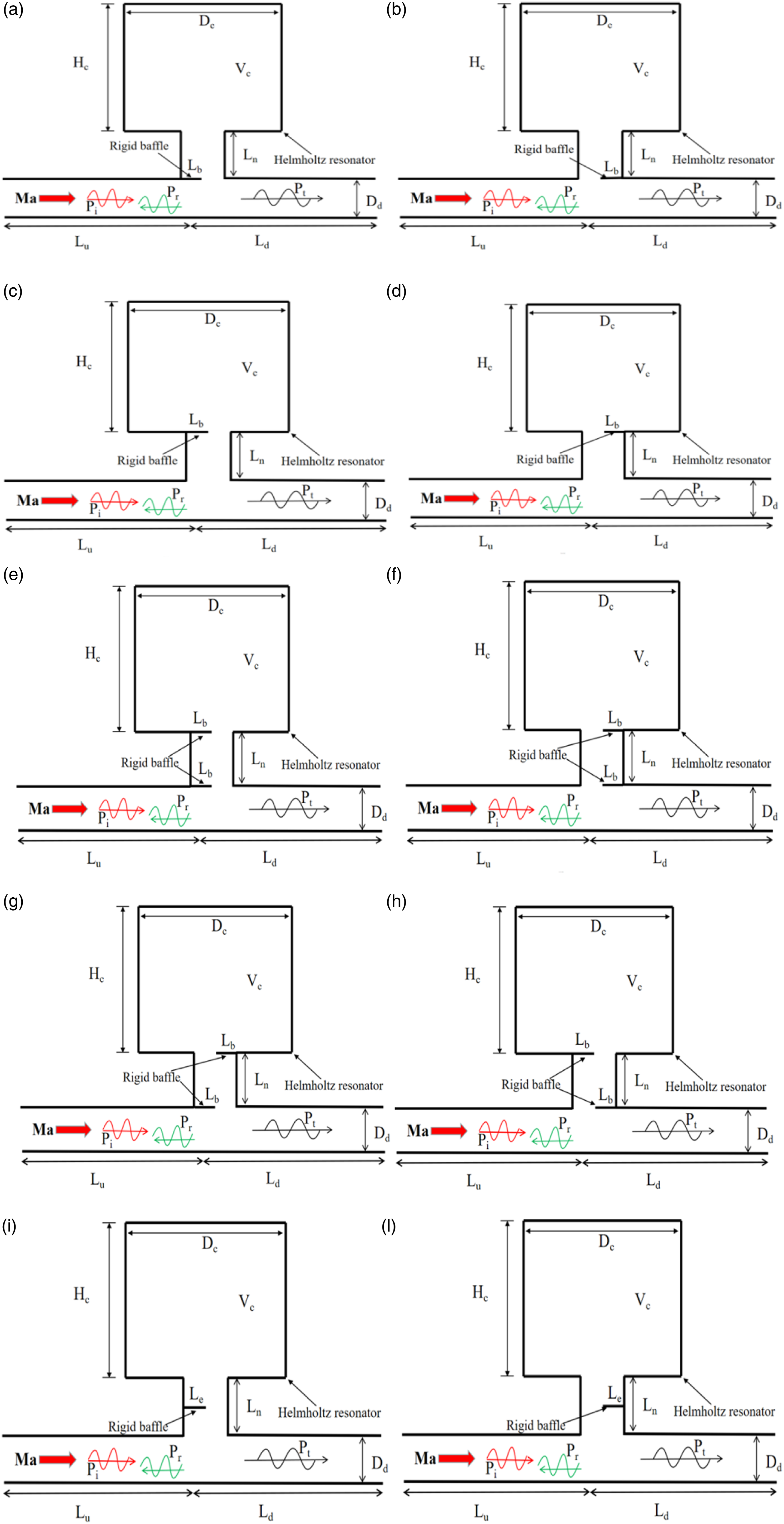
The 2D numerical model is governed by linearized NS equations, since we consider low Mach number incompressible viscous flow (Ma<0.2). Thus, the mass conservation relationship30-34 holds as

The momentum conservation6,18 holds as

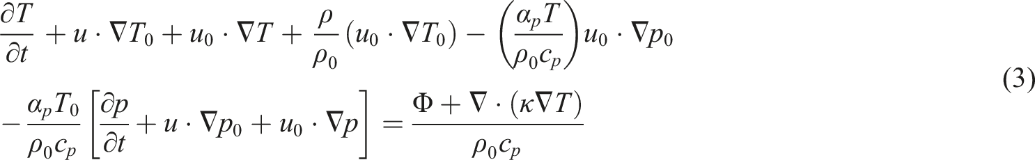
Energy conservation6,18 relationship holds:


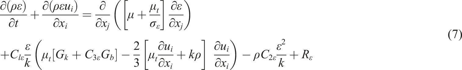
Turbulent motions lead to Reynolds stress in the presence of a mean flow. The Reynolds stress depends on the cross-product terms between fluctuating velocities in different directions.37-40 Thus, the turbulence and turbulence stress need to be modeled. In the literature, LES (large eddy simulation) or DNS (direct numerical simulations) could be conducted. However, it is computationally costly. To reduce computational time and cost, RANS (Reynolds-Averaged Navier–Stokes) simulations could generally performed, which offers k-ε, k-ω, and SST models being available. For simplicity, we prefer
The

Note that the above governing equations are nonlinear one. By conducting linearization and neglecting second-order terms including
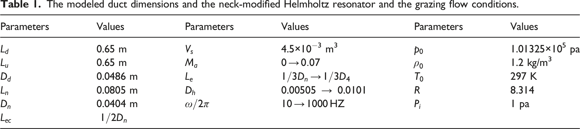
Duct dimensions, flow conditions, and numerical meshes
The modeled duct dimensions and the neck-modified Helmholtz resonator and the grazing flow conditions.
The numerical meshes are depicted in Figure 2. Basing on our mesh-independence study, a very finer mesh with 683,226 cells in total is chosen in our simulations with Unstructured computational meshes of the models as the neck-modified resonator used. (a) 683,226 cells and (b) 63,593 cells.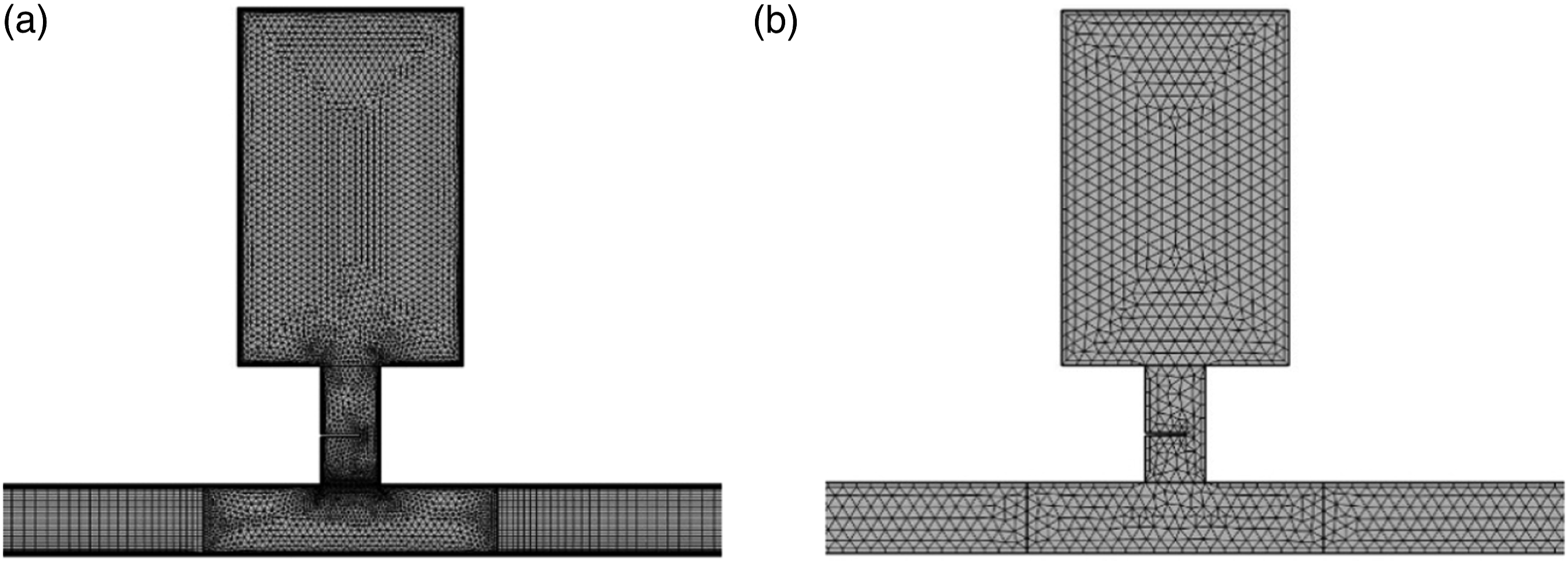
Model validation
Before applying the model, it is validated by comparing the present simulations’ results with Selamet et al. experimental ones,
3
as the same parameters and flow and boundary conditions are applied on a pipe with a conventional Helmholtz resonator applied. For achieve consistency with experimentally measured ranges, the numerically interested frequency is ranged from 10 to 250 Hz. The resonator’s damping is characterized by TL (transmission loss). It is defined as
Figure 3 depicts the comparison of the present results and the previous 2D/3D numerical and experimental ones,
3
as the grazing flow Ma is set to 0, 0.03, and 0.07.46,47 Good agreements are observed, since the maximum TL and the corresponding resonant frequency are closed to the previous experimental and numerical results. Note that the maximum TL is obtained by setting the frequency incremental step of 2 Hz. It is found that the maximum TL depends on the incremental frequency step. For example, 2 Hz and 5 Hz frequency steps lead to different Maximum TL. Comparison studies are conducted between the step of 1 Hz and 2 Hz. There are less than 5% difference. Thus, we choose the 2 Hz frequency incremental step, and conduct the following simulations. Comparing the present simulations results with previous 3D numerical and the experimental results available in the literature, as Ma is set to (a) Ma=0, (b) Ma=0.03, and (c) Ma=0.07.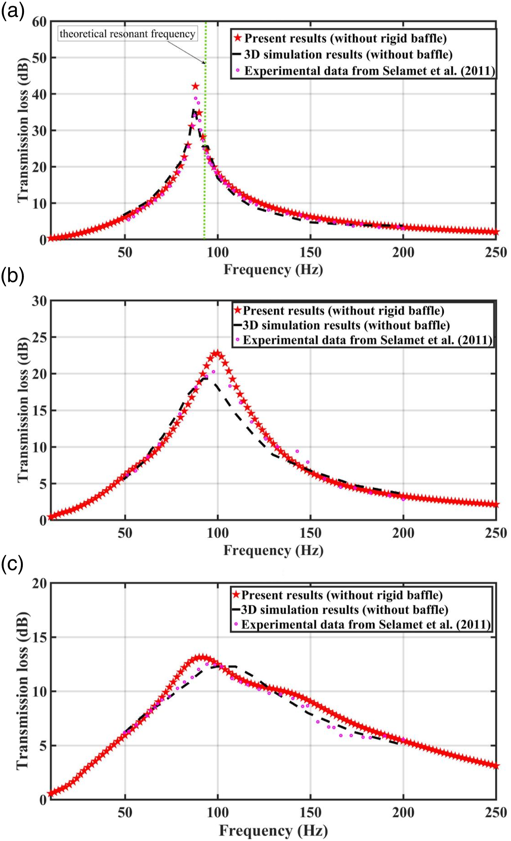
Effect of implementing a single baffle at the neck
Now the proposed model is applied to examine the noise attenuation behaviors of the modified Helmholtz resonators48-50 with a rigid baffle implemented at its neck, as there is a grazing duct flow. This flow is typically observed in real engine systems. Figure 4 illustrates the comparison between the TL (transmission loss) behaviors of the conventional Helmholtz resonator and the structure-modified resonators (i.e., Design A, B, C, and D). It can be seen that the maximum TL and the corresponding resonant frequency of the modified resonator (i.e., Design A, B, C, and D) are reduced in comparison with those of the conventional resonators, in the absence of the grazing flow, that is, Ma = 0. Comparing Figures 4(a) to (d) reveals that the variation of the baffle implementation does not lead to the change of the TLmax and the corresponding resonant frequency. Comparison of the TL performance between the conventional Helmholtz resonator and the structure-modified resonator (i.e., Design A, B, C, and D), as Ma=0 and the length of the baffle Le/Dn=0.5.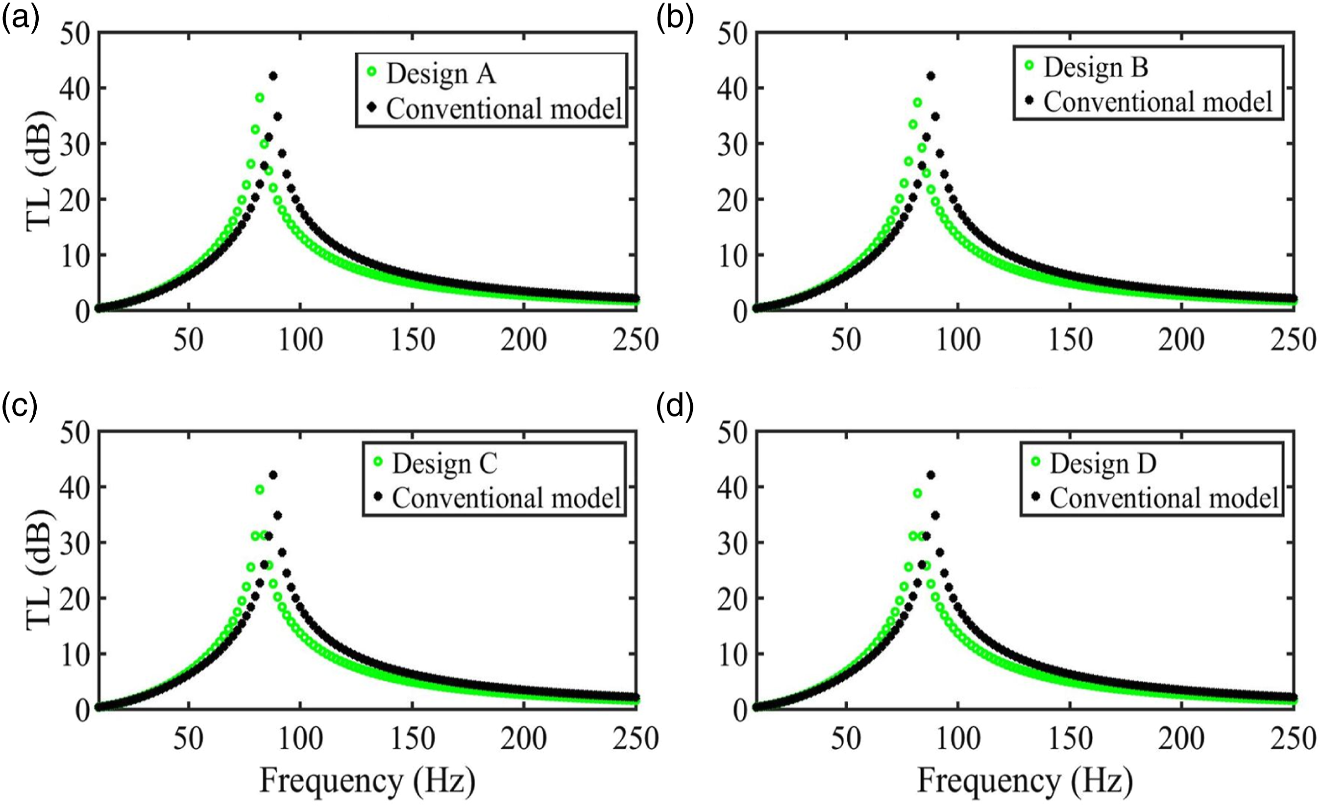
Figure 5 illustrates the comparison of the TL behaviors between the conventional Helmholtz resonator and the structure-modified resonator (i.e., Design A, B, C, and D), as Ma=0.03. A closer observation shows that the TLmax of the Design A is reduced. However, the resonant frequency looks like unchanged. Similar findings are observed on Design B, as shown in Figure 5(b). However, as far as Designs C and D are concerned, the maximum TL and the corresponding resonance frequencies are decreased, in comparison with the conventional HR51-54 in the absence of the baffle. Comparing Figure 5(a) with Figure 4(a) shows that the TLmax is much decreased. This is most likely due to the increase of the grazing flow Mach number. However, the corresponding resonant frequency is increased somehow, and quite close to that of the conventional resonator. Similar findings can be obtained, when comparing Figures 5(b) to (d) with Figures 4(b) to (d), respectively. Comparison of the TL performance between the conventional Helmholtz resonator and the structure-modified resonator (i.e., Design A, B, C, and D), as Ma=0.03 and the length of the baffle Le/Dn=0.5.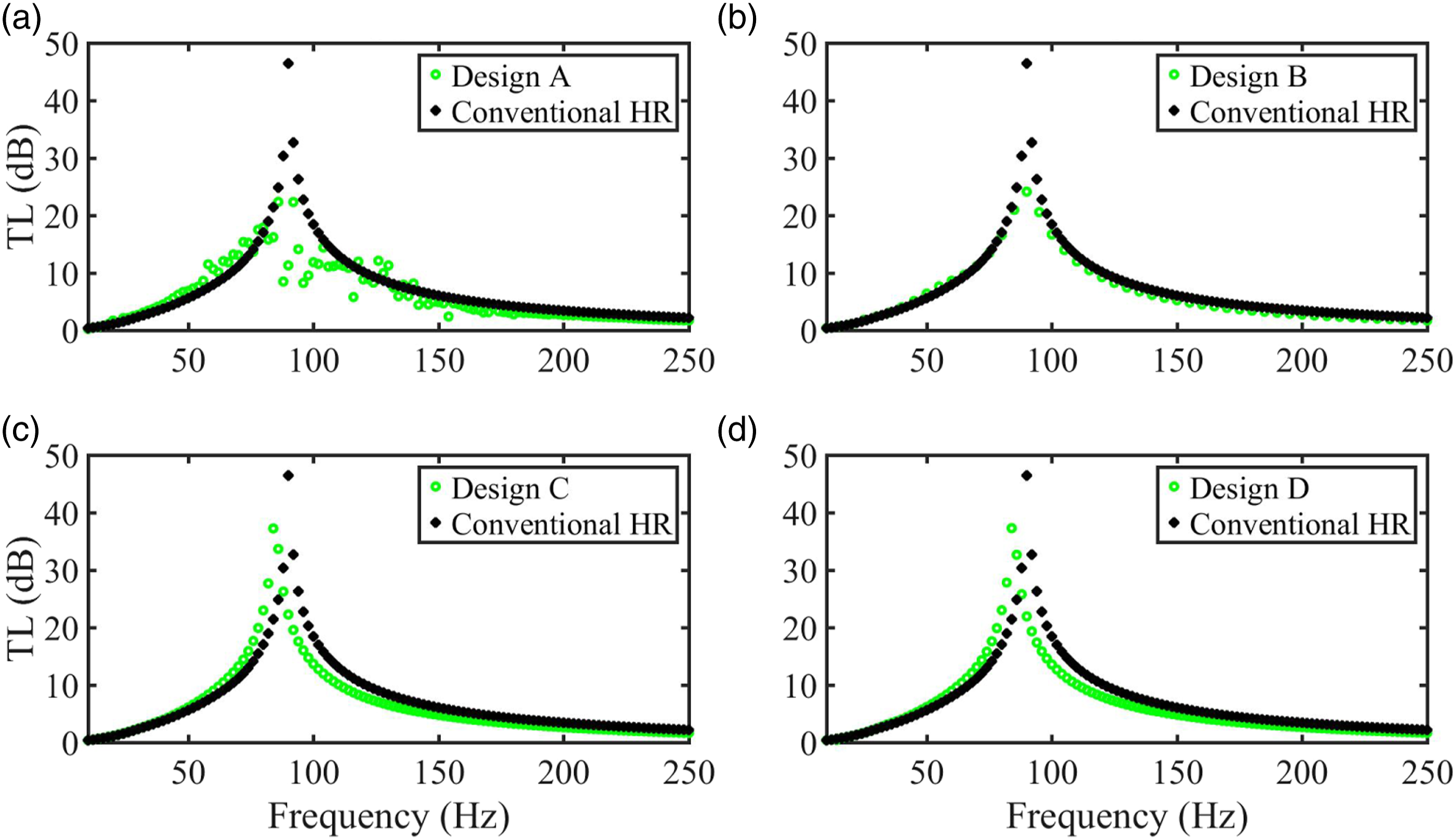
As the duct flow Mach number is further raised to 0.07, the TL performances are show in Figure 6. It can be seen from Figure 6(a) that the maximum TL of Design A is improved. However, the corresponding resonant frequency of TLmax is decreased. Similar resonant frequency reduction is observed on Figures 6(b) to (d). However, Figure 6(c) shows an improved maximum TL comparing with that of the conventional resonator. This reveals that Design C is a better one. It means that implementing a baffle at the upstream end of the neck is a good design. Figure 6(d) reveals that compared with the conventional model of Helmholtz resonator, the global TLmax and the Design D’s resonance frequency are both reduced. Comparing Figure 6(a) with Figure 5(a) reveals that both TLmax and the corresponding resonant frequencies are reduced somehow. This is most likely due to the increase of the grazing flow Mach numer. Similar findings are observed from Figures 6(b) to (d). Predicted transmission loss changed with the acoustic forcing frequency between Designs A, B, C, and D and the conventional model separately, as the grazing flow Mach number is set to 0.07 and the length of the baffle Le/Dn=0.5.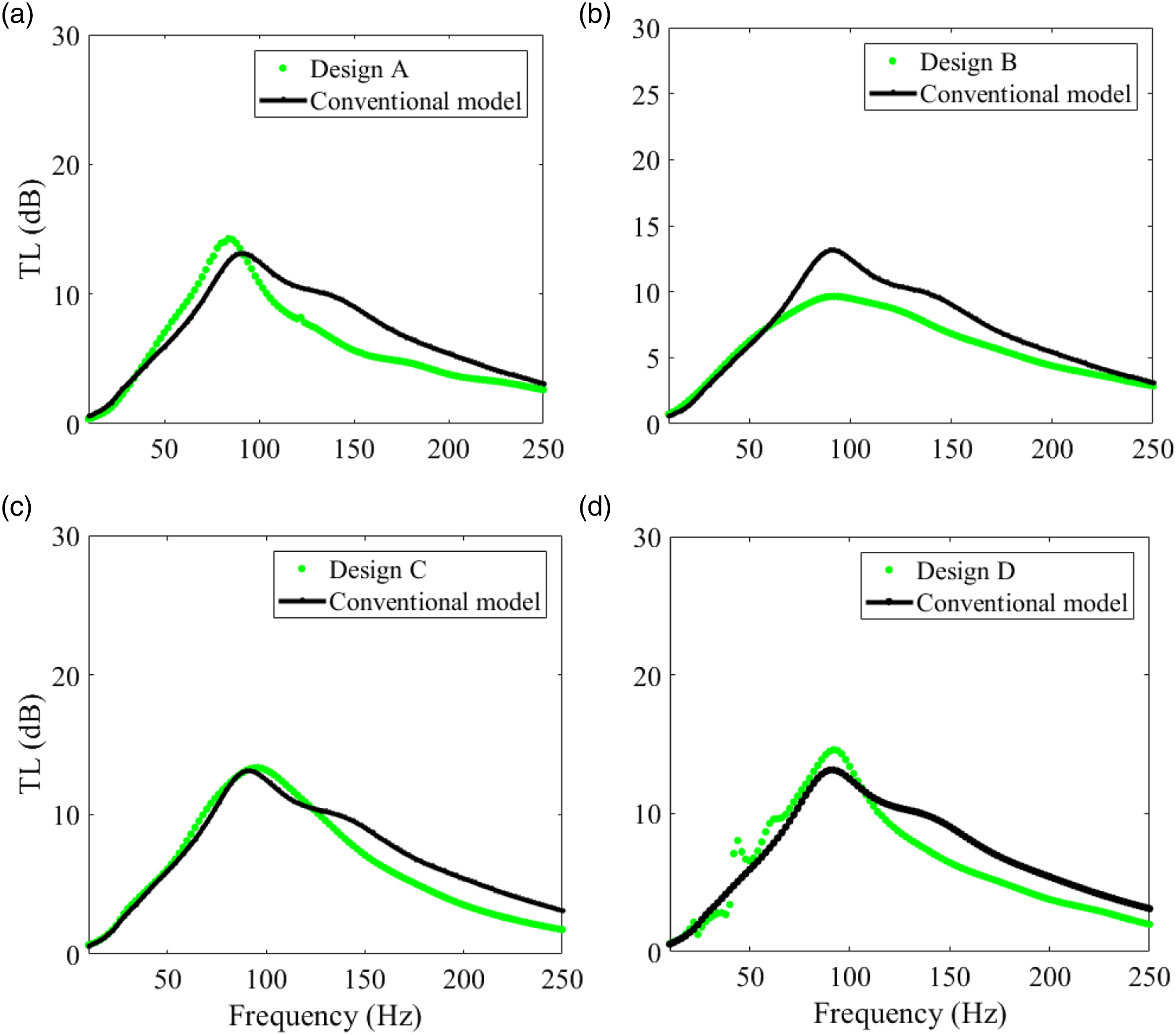
Effect of implementing double-baffle at the neck
Figure 7 shows the comparison of the structure-modified resonator with two rigid baffles applied at its neck with the conventional resonator,55-59 as Ma=0. It can be observed that the global TLmax and the corresponding resonance frequencies of the Design, E, F, G, and H are reduced under the condition of Ma = 0. Comparing Figures 7(a) to (d) reveals that when the Mach number is zero, the variations of the baffle implementation configurations, i.e. Design E, F, G, and H give rise to a negligible change of the resonant frequency and TLmax. However, comparing with the conventional resonator, the resonant frequency and TLmax are reduced somehow. Predicted transmission loss changed with the acoustic forcing frequency between Design E, F, G, and H and the conventional model separately, as the grazing flow Mach number is set to 0 and the length of the baffle Le/Dn=0.5.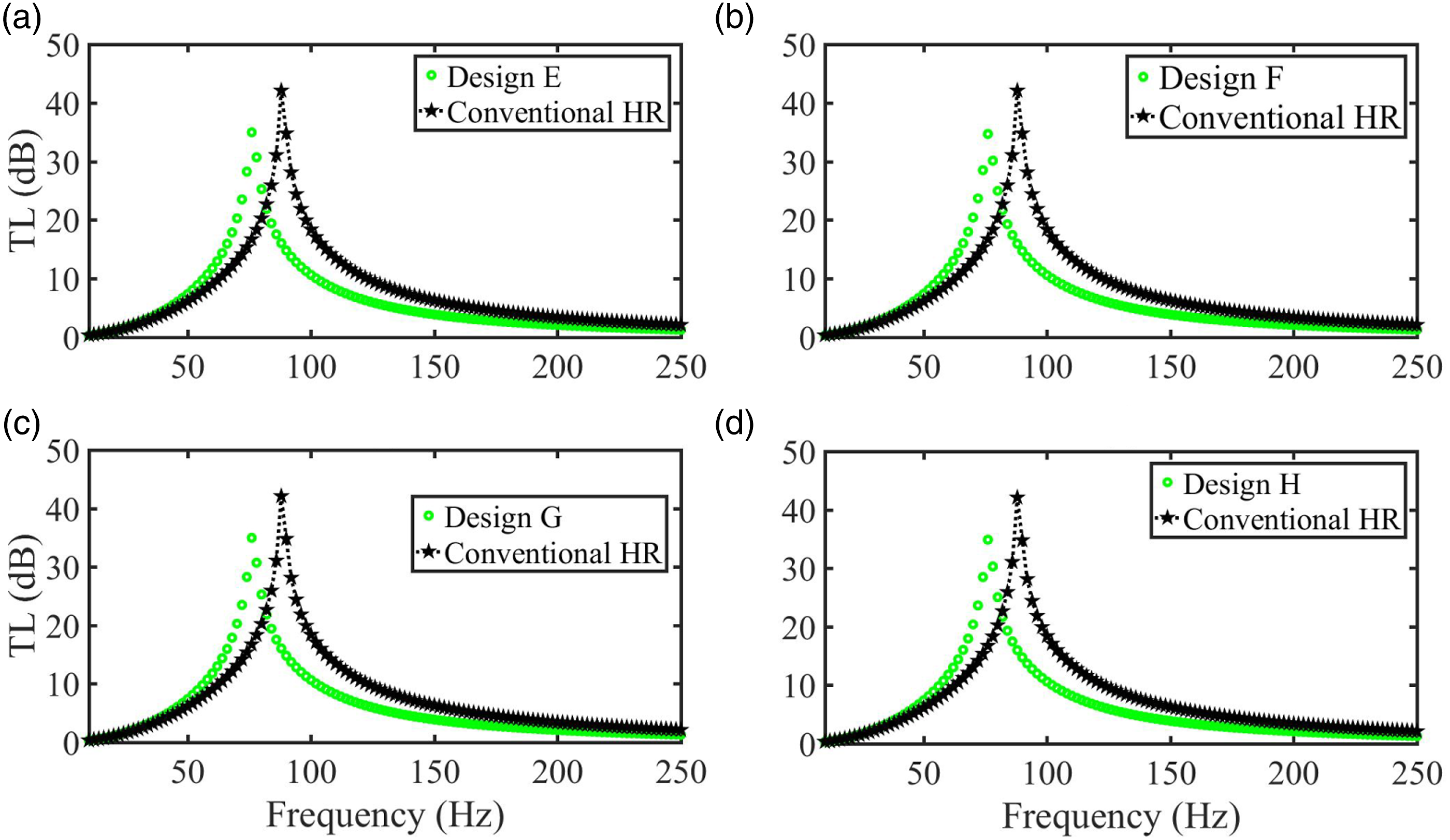
Figure 8 shows the comparison of the Designs E, F, G, and H with the conventional resonator, as Ma is increased to Ma=0.03. It can be seen the maximum TL and the corresponding resonant frequencies are reduced for all designs. However, in the low frequency range of 10<ω/2π<100 Hz, Designs F and H produce multiple resonant peaks (see Figures 8(b) and (d)). In addition, the increase of the Mach number leads to a reduced TLmax in comparison with those shown in Figure 7. Comparing Design H (see Figure 8(d)) with Designs E, F, and G reveals that the Design H is associated with an improved TLmax in the presence of the Ma=0.03 grazing flow. Predicted transmission loss changed with the acoustic forcing frequency between Designs E, F, G, and H and the conventional model separately, as the grazing flow Mach number is set to 0.03 and the length of the baffle Le/Dn=0.5.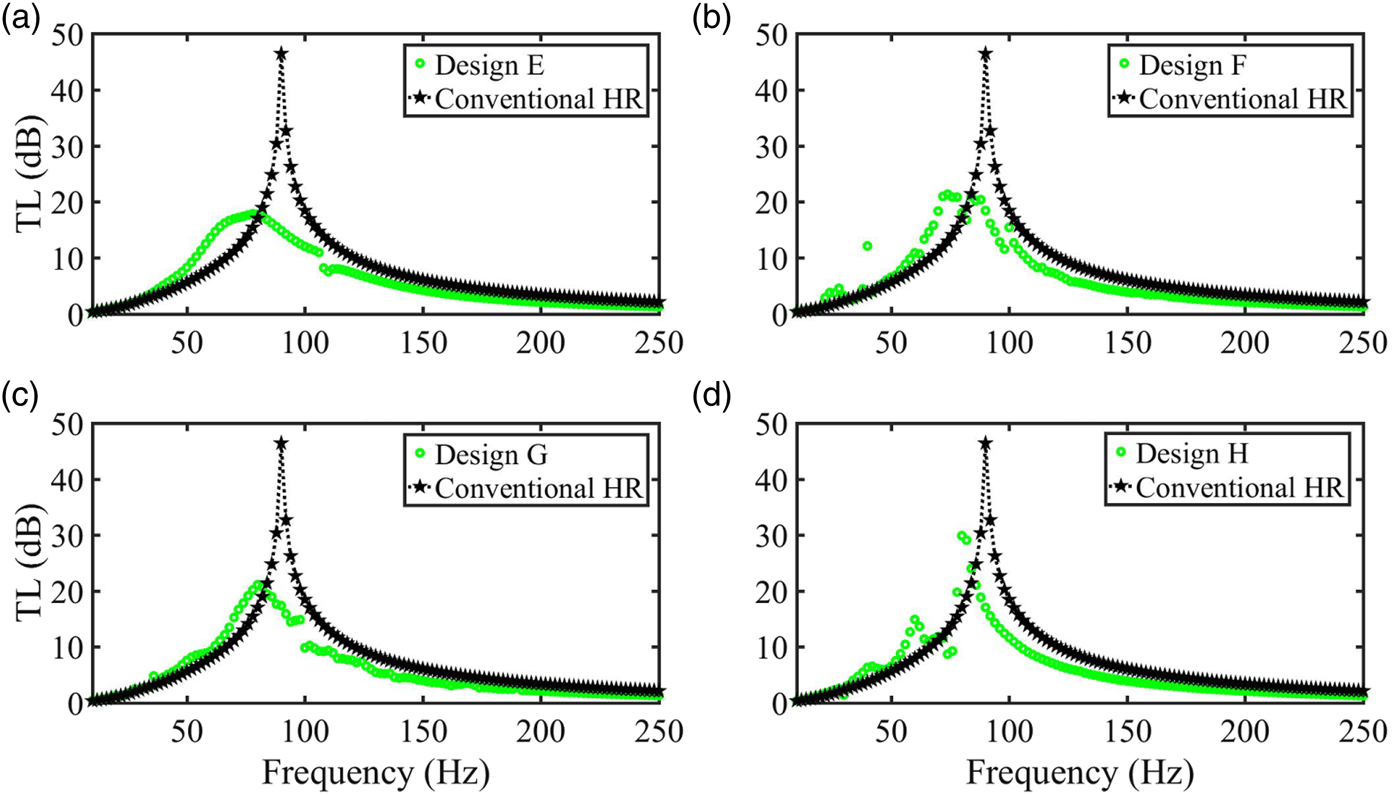
When the duct flow Mach number is increased to Ma=0.07, the TL performances of Designs E, F, G, and H are compared with the conventional resonator. This is depicted in Figure 9. It can be observed from Figures 9(a) to (d) that the TLmax is further reduced, as the Mach number is increased (see Figure 7 and 8). This general trend is consistent with the performance change of the conventional resonator, as the Mach number is increased. In addition, Figure 9(c) shows that over certain frequency range, TL is negative. It means that implementing the two baffles at the neck gives rise to noise generation. This is highly undesirable.60,61 Predicted transmission loss changed with the acoustic forcing frequency between Designs E, F, G, and H and the conventional model separately, as Ma= 0.07 and the length of the baffle Le/Dn=0.5.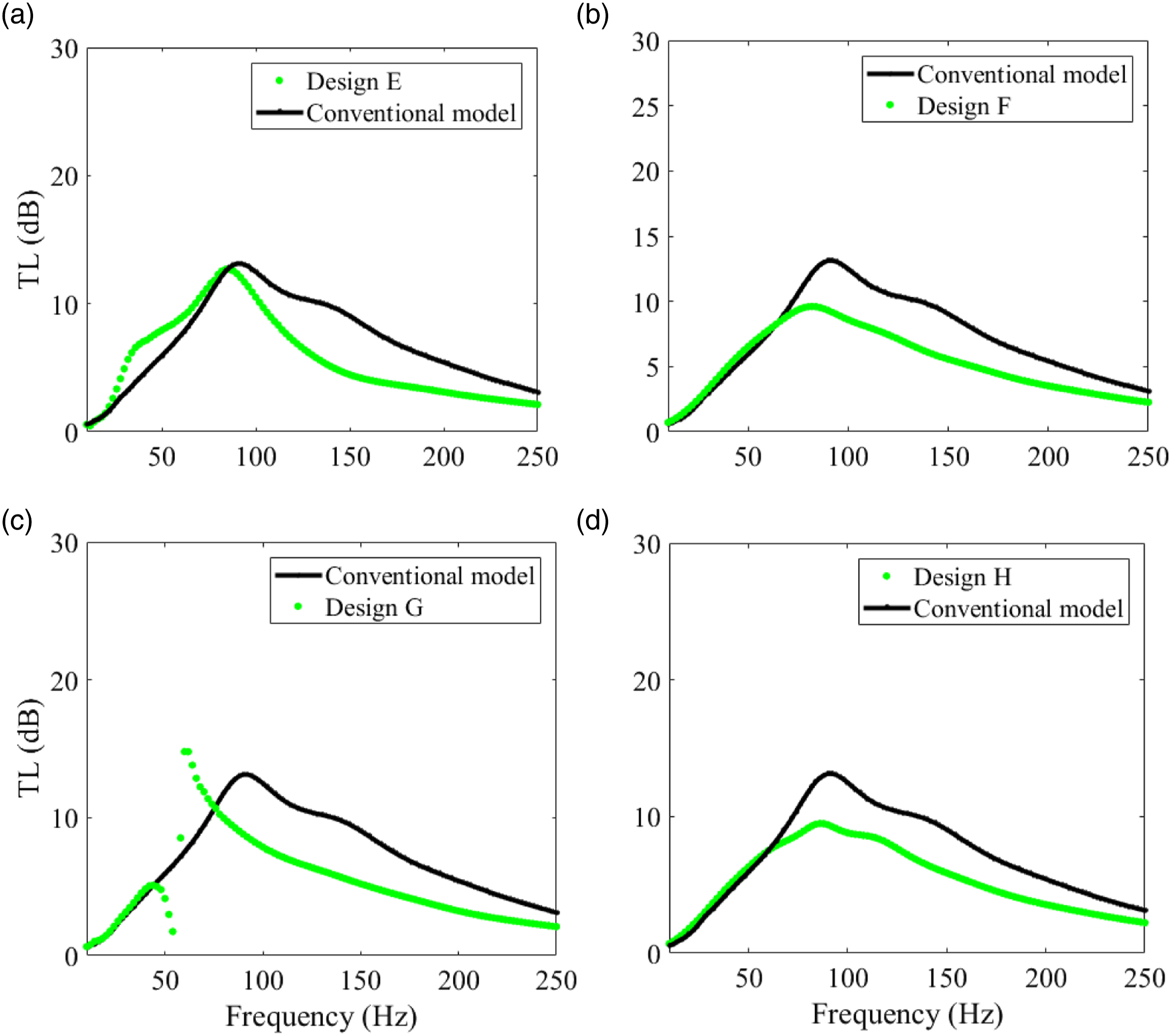
To shed light on the fundamental physics contributing to TL and to illustrate the vortex shedding mechanism and the shear layer separating across the resonator neck with a rigid baffle, the following figure illustrates the 2D contours of vorticity. Figure 10 is the vortex contour plots of Designs A, B, C, D, E, F, G, and H, as the duct flow Mach number is set to Ma = 0.07. It could be observed that a clock-wise vortex is locked in the cavity. Design C (see Figure 10(c)) is involved with the baffle implemented on the upstream end of the resonator neck, which blocks partially and squeezes the air flow through the neck into the cavity. The enhanced vortex in the cavity is believed to contribute to the improved transmission losses as observed on Figure 6(c). The implementation of the two baffles at the neck does not lead to an improvement to the TLmax in comparison with that of the single baffle configuration. This is most likely due to the “preventing” effect of vortex shedding generation as shown in Figure 10 Comparison of the vorticity contours near the neck of Design A (a), B(b), C(c), D (d), E (e), F(f), G(g), and H (h), as he length of the baffle Le/Dn is set 0.5 and Ma=0.07.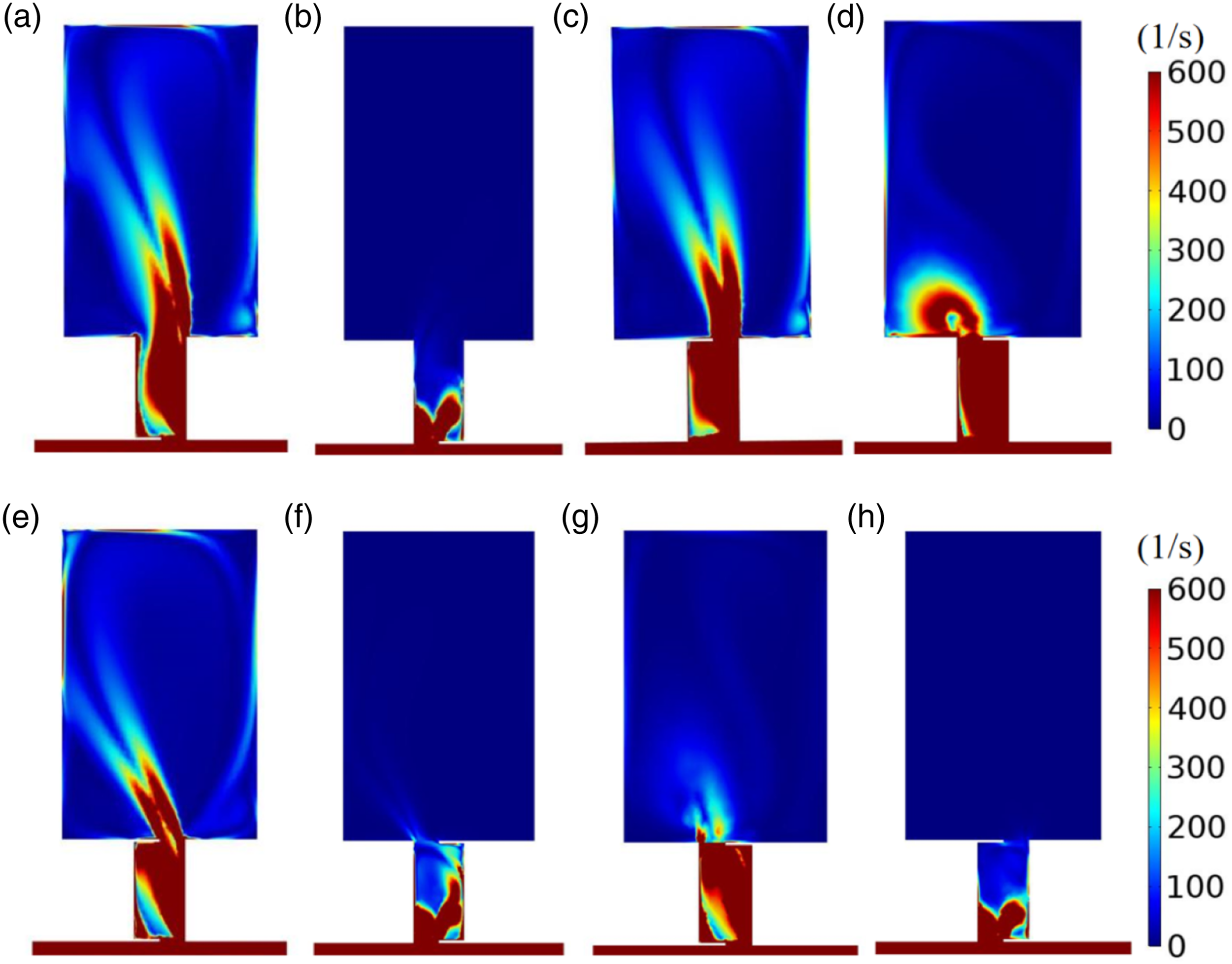
Effect of the length of the single baffle
The foregoing results reveal that implementing the two baffles may not lead to improved noise damping performance. However, applying single baffle on the upstream end of the resonator neck (see Design C) could give rise to a larger TLmax and a lower resonant frequency (see Figure 6(c)). We will focus on the design of implementing a single baffle on the upstream end of the resonator neck.63-66
It is interesting to know if the length of the baffle can affect the TLmax and the corresponding resonant frequency. Figure 11 shows the noise damping67-69 performance of Design I with different lengths in comparison with the conventional resonator, as Ma = 0. It can be seen from Figure 11(a) that when the baffle length is set to 2/3, the resonant frequency and TLmax are much smaller than those of the conventional resonator. However, as the baffle length is decreased to ½ (see Figure 11(b)) or to 1/3 (see Figure 11(c)), the resonant frequency and TLmax are almost the same as those of the conventional resonator. This is most likely due to the absence of the grazing flow, that is, Ma=0. In general, reducing the baffle length (normalized with the resonant neck diameter) from 2/3 to 1/3 leads to an improved TLmax and increased resonant frequency.70-74 This could be easily observed and compared from Figures 11(a) to (c). Predicted transmission loss changed with the acoustic forcing frequency between Design I and the conventional resonator separately, as the single baffle is implemented, Ma=0, and the length of the baffle Le/Dn is set to either 2/3 (a),1/2 (b), or 1/3 (c).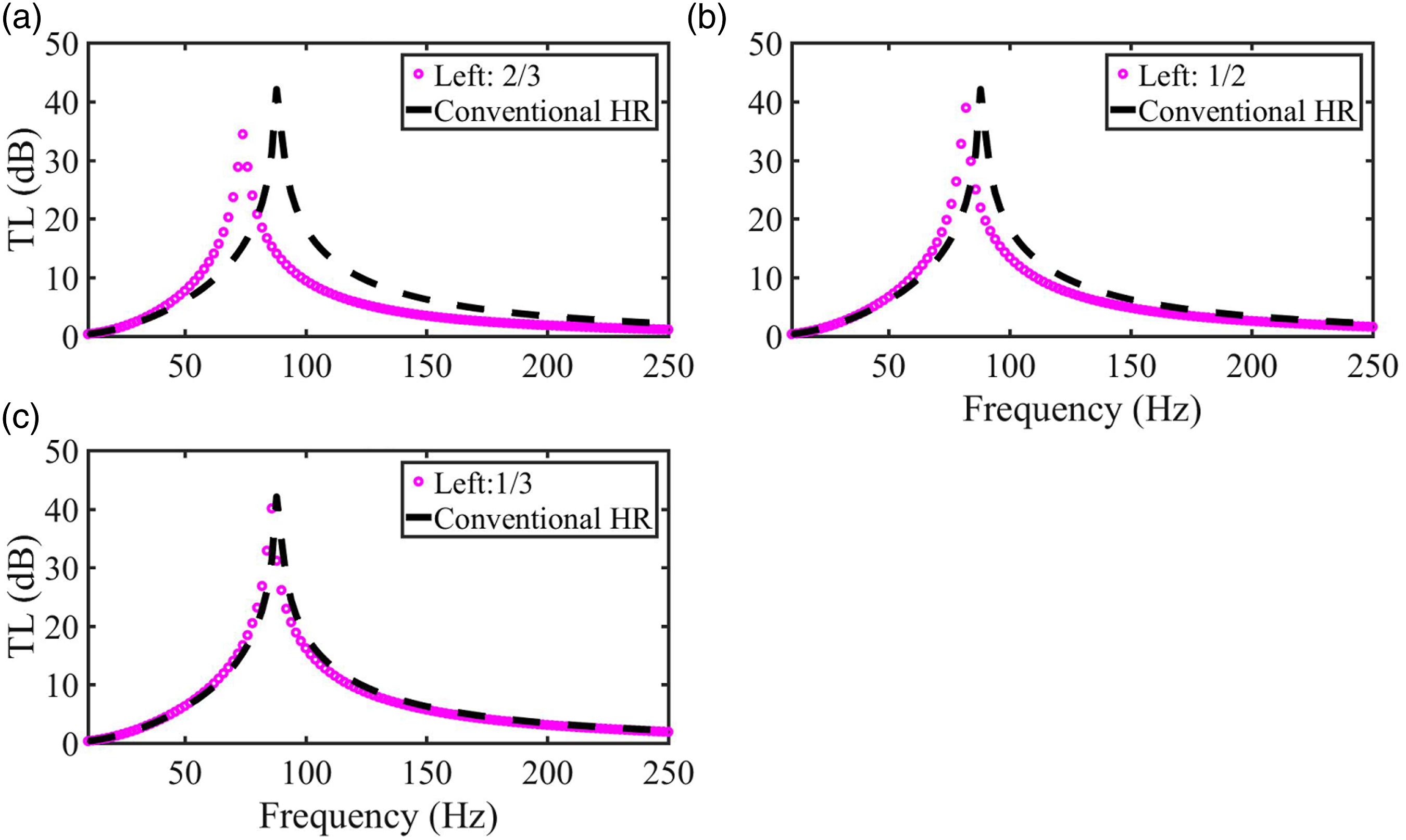
Figure 12 shows the noise damping performances of the Design I in comparison with that of the conventional resonator, as Ma = 0.07. It can be seen from Figure 12(c) that when the baffle length is 1/3, then the resonant frequency is coincident with that of the conventional resonator.75,76 The maximum TLmax is almost unchanged. However, as the baffle length is increased to ½ (see Figure 12(b) or 2/3 (see Figure 12(a)) that TLmax and the corresponding resonant frequencies are reduced in comparison with those of the conventional resonator. In general, Design I with different lengths is not performing better in terms of the noise damping TL, especially as Mach number is large (Ma≥0.07). Variation of transmission loss with the forcing frequency between three new model (left; 2/3,1/2,1/3) and conventional model separately, as Ma = 0.07.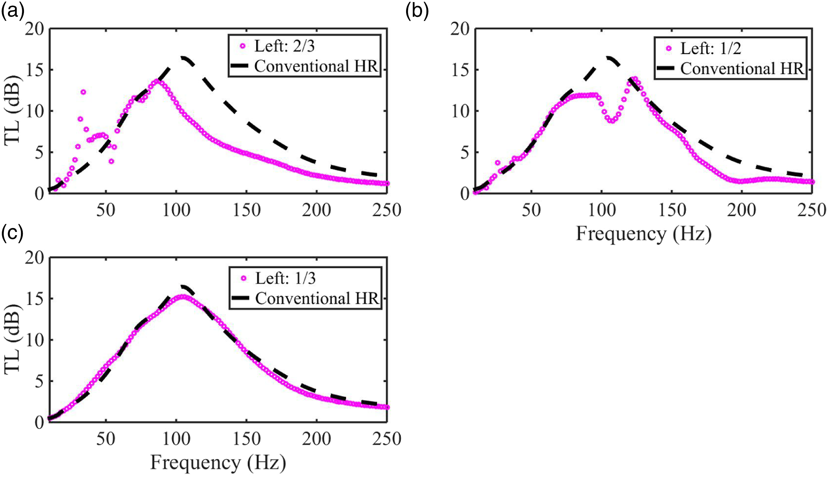
In general, implementing a baffle at the resonator neck could be an approach to optimize the noise attenuating performances and behaviors of such neck-modified Helmholtz resonators. These structured-modified resonators are associated with little failure risks in operation, like active noise control. Thus it has some potential being utilized in practical engines77,78 to minimize thermos-driven acoustic oscillations and to stabilize unstable thermoacoustic combustors.
Discussion and conclusions
In the present work, we attempt to modify the resonator neck structure to improve its noise damping performance. For this, a 2D model of neck-modified Helmholtz resonators is developed and used to predict its transmission loss (TL) performances in the presence of a duct grazing flow. The model is first validated with comparison with previous experimental and 2D/3D numerical results available. After validating the model, it is applied to predict noise attenuating behaviors of the 10 neck-modified Helmholtz resonators, as there is a low Mach number grazing flow and a rigid baffle is implemented at its neck. The effects of 1) the baffle attached to the upstream or downstream sidewall of the neck ends (the configurations of a single baffle or double baffles are considered and compared), 2) the baffle length, 3) the baffle location, and 4) the grazing flow low Mach number are evaluated. Interesting concluding remarks are obtained as • When the rigid baffle is applied on the upstream of the neck sidewall, the vortex locked in the cavity is enhanced, and its noise damping performance is better than that of the rigid baffle on the right side. • With the increase of the Mach number of the grazing flow, the rigid baffle affects the flow direction and trajectory of the grazing flow. • Apply two baffles at its neck does not lead to a better noise damping performance in comparison with that of the single baffle case, especially applied it on the upstream neck end. This is most likely due to the grazing flow-sound-structure interaction, which affects the vortex generation in the resonator cavity. • The classical formula • Implementing a single baffle at the upstream end of the resonator neck (Design C) is observed to be involved with improved TLmax and reduced resonant frequency.
In summary, we propose and examine the neck-modified designs of Helmholtz resonators with a rigid baffle implemented at its neck, aiming to improve its noise damping performances and providing an optimum resonator design. The developed model is in frequency domain with a low computational cost. However, it does provide the insights on the acoustics and flow characteristics resulting from the grazing flow-sound-structure interaction. Once it is well validated, then it can be applied for optimization design studies.
Footnotes
Acknowledgments
The authors would like to thank University of Canterbury and Jiangsu University of Science and Technology for providing the studentships.
Declaration of conflicting interests
The author(s) declared no potential conflicts of interest with respect to the research, authorship, and/or publication of this article.
Funding
The author(s) disclosed receipt of the following financial support for the research, authorship, and/or publication of this article: This work was supported by the University of Canterbury and Jiangsu University of Science and Technology.