
Abstract
Vibration isolation of a floating raft system typically found in a marine application is of concern in this paper. Housed on the raft are electrical motors each driving two counter rotating shafts with eccentric masses attached. An experimental study is described in which vibration transmitted to a large-scale, laboratory-based hull-like structure is attenuated by using three measures. They are, the use of vibration isolators between the raft and the hull-like structure, adjustment of the phase of the electrical supply between the motors to minimize vibration transmitted through the isolators, and the application of an active vibration control system using hydraulic actuators placed in parallel with the isolators. The results show that this combination of measures is extremely effective at reducing the vibration transmission to the hull-like structure, and consequent reduction the sound radiation. It is more effective than the application of any of the vibration control measures applied by themselves.
Introduction
Vibration isolation using passive isolators is widely used in marine applications through different configurations, such as a single-stage, a double-stage, and a floating raft isolation system. However, a passive isolation system has fundamental limitations, and can only achieve a certain level of vibration isolation. Active and semi-active vibration isolation has been employed in marine applications, for example,1–12 especially to improve isolation performance in the low frequency range. However, an active vibration isolation system is costly, requires a power supply and a digital controller, and still needs a back-up system of conventional passive isolators. Even for a semi-active vibration system, which is less expensive than an active system, it is more complex than a passive system.
If the machines generating the vibration are electrical, then synchrophasing may be an alternative vibration control strategy. The idea behind this can be traced back many years to the control of vibration by adjusting the speed and phase angles of two engines in a steam ship. 13 However, little attention has been paid to the control the vibration of raft-mounted machinery using this control scheme.14,15 It has been used to control sound in aircraft cabins16–18 and ducts.19,20 Recent research on synchrophasing in aircraft has concentrated on active synchrophasing, using microphones and accelerometers positioned throughout the aircraft, together with adaptive optimization techniques to minimize the cabin noise and vibration over a wider range of flight conditions.21,22 Propeller Signature Theory 23 has been employed to determine the optimum synchrophasing angles.
Recently, Dench et al. 24 applied synchrophasing to control the vibration generated by multiple machines on a machinery raft in a marine application. An extension of this has been presented by Yang et al.25,26 to investigate the application of synchrophasing control to multiple machines on a large-scale floating raft system, both theoretically and experimentally. Four vibration exciters, each of them driven by a phase asynchronous motor, were used to simulate rotating machines on the raft. The phase of the electrical supply to the motors was adjusted by a synchrophasing control scheme, which used a genetic algorithm to determine the optimum phases between the machines.
In this paper, an experimental study is presented in which three measures are applied to control the vibration of a machinery raft system. They are the use of vibration isolators between the raft and the hull-like structure, adjustment of the phase of the electrical supply between the motors to minimize vibration transmitted through the isolators, and the application of an active vibration control system using hydraulic actuators placed in parallel with the isolators. It is believed that this is the first time these measures have been applied together. The aim of this paper, therefore, is to demonstrate that such a system can be effective in a large-scale laboratory-based system.
Description of the test rig
The combined synchrophasing and active vibration control system was applied to a large-scale laboratory-based test rig, photographs of which are shown in Figure 1. It was designed to be representative of a typical shipborne machinery installation. The test rig consists of a 6.2 m × 5.2 m × 0.4 m floating raft constructed from 16 I-shaped steel beams. This is supported on a 7 m × 6 m × 0.7 m flexible hull-like structure by 18 BE-400 type resilient isolators mounted on 18 steel pillars. To isolate the hull-like structure from the laboratory floor, 26 pneumatic isolators are integrated into the pillars to give a natural frequency of about 1.7 Hz. 22 A schematic diagram showing the hull-like structure is shown in Figure 2. Four vibration exciters, one of which is shown in Figure 1(b), are fitted to top of the floating raft. They each comprise two counter rotating shafts with similar unbalanced masses, and are driven by an AC Italvibras ITV-VR/1210 type motor. The speed range of each exciter is 0–6000 r/min (0–100 Hz). They were controlled using a Simotion D425 motion controller, and could be either switched off or on to excite the raft. Four hydraulic actuators, which were used as secondary sources, are located symmetrically between the raft. One of these is shown in Figure 1(c) and their positions can be seen in Figure 2.27,28 They can each generate a force of 8.9 kN over a frequency range of 0–300 Hz. The whole system weighs about eight tons.
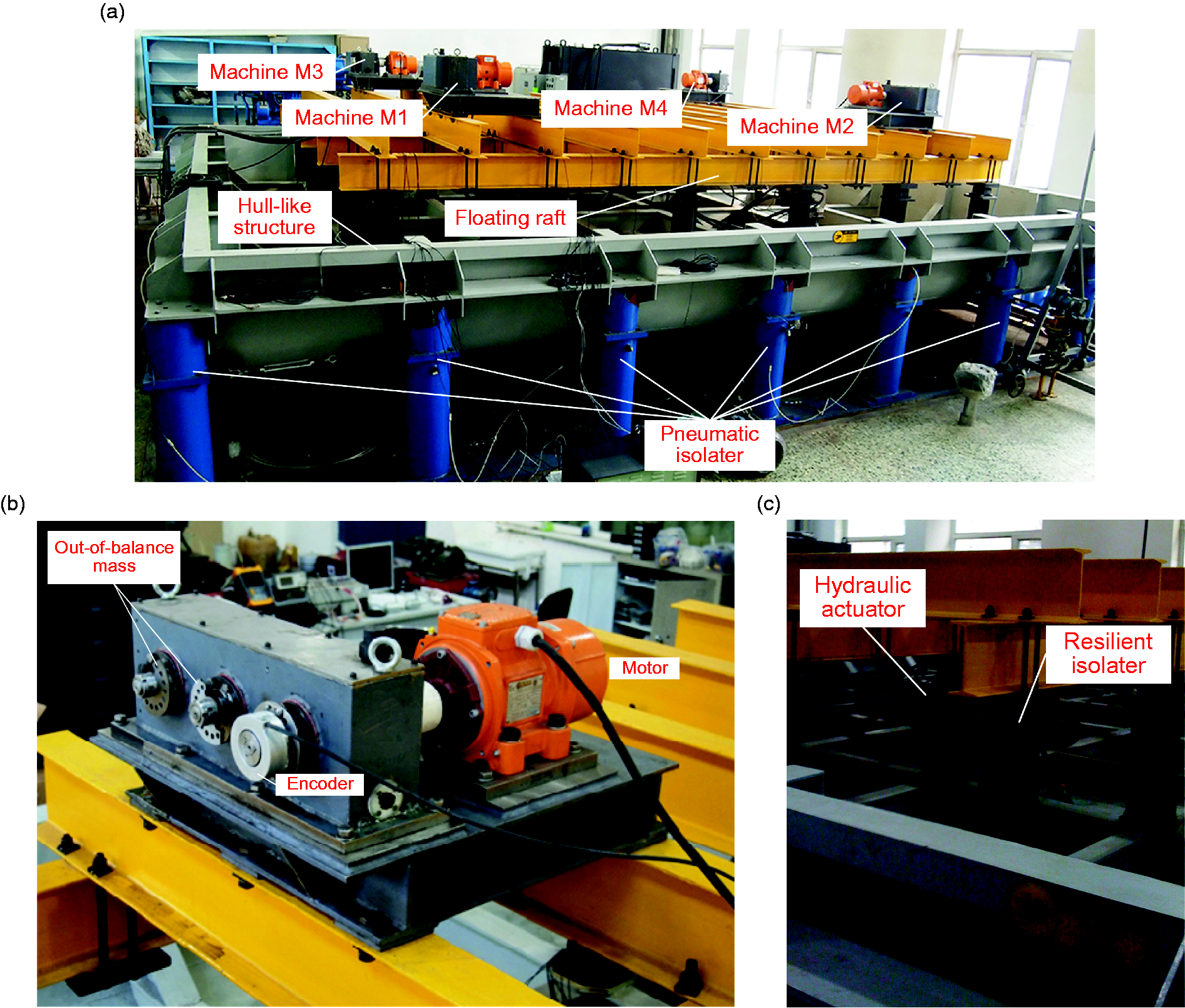
Photographs of the large-scale vibration isolation test-rig. (a) The floating raft vibration isolation system on the hull-like structure, (b) one of the rotating machines, (c) one of the 18 resilient isolators connecting the raft to the hull-like structure, and one of the four hydraulic actuators acting in parallel with the isolators.
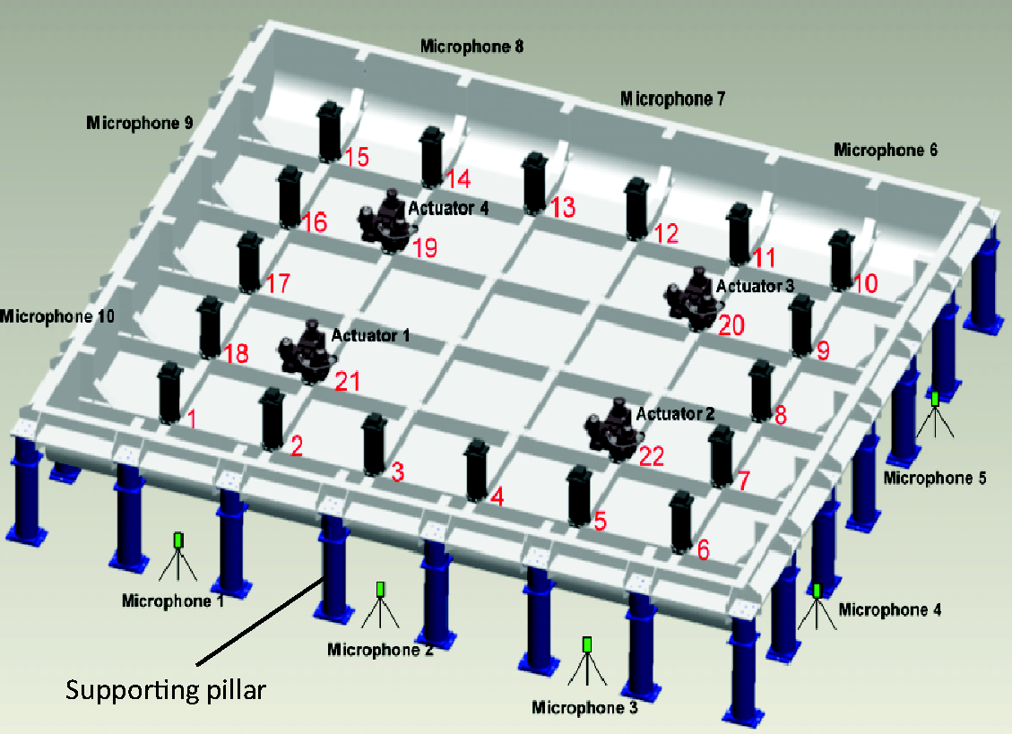
Schematic diagram of the hull-like structure showing the supporting pillars, the isolators that support the floating raft system, and the four actuators used for active control. Also shown are the microphones used to monitor the noise close to the hull-like structure.
Vibration control system
As mentioned previously, the aim of this paper is to demonstrate the effectiveness of the combination of three vibration control measures. They are the passive isolation between the floating raft and the hull-like structure, the synchrophasing of the vibration sources, and the active control system using the four hydraulic actuators. This requires a control system and an array of sensors. Twenty-two accelerometers were located at 18 pillars and four additional positions on the hull-like structure, whose outputs were used to calculate a cost function. This was the mean of the squares of modulus of the accelerations measured by the four accelerometers. Another six accelerometers were placed on the raft to evaluate the vibration of the raft when the synchrophasing and active control system were activated. Ten microphones were also located around the hull-like structure as shown in Figure 2. A B&K 3560 D system with Pulse software was used to measure all the noise and vibration.
To help determine the best positions for the four accelerometers for the active control system, a finite element analysis of the system was carried out together with some modal testing. 29 It was found that the first four modes are rigid-body modes with natural frequencies of 1.7 Hz—heave, 2.1 Hz—pitch, 3.4 Hz—roll, and 5.1 Hz—torsion. The fifth mode at 6.0 Hz is a warping mode. The sixth mode at 20.3 Hz is a beam-like bending mode of the floating raft, and the seventh mode at 22.1 Hz is a bending mode similar to that of the first mode of a simply-supported plate.
A block diagram of the active synchrophasing control system, in which more details are shown, is in Figure 3. The signals from the rotary sensors from each of the motors driving the four exciters were encoded and sent to the Simotion D425 motion controller. The relative phases were calculated from these data. The optimal phase combination was then calculated using the cost function and the genetic algorithm described by Yang et al. 25 The signals from the rotary sensors were also filtered by band pass filters to generate the periodic reference signal which contains the same harmonics as the vibration of the hull-like structure. The reference signal was sampled by a TMSVC33 DSP system which was used as the controller in the feed-forward active control system. The control signals were passed through band pass filters to the servo valve controller to control the hydraulic actuators. The generated forces acted on the raft and hull-like structure simultaneously to reduce the vibration of the hull-like structure.
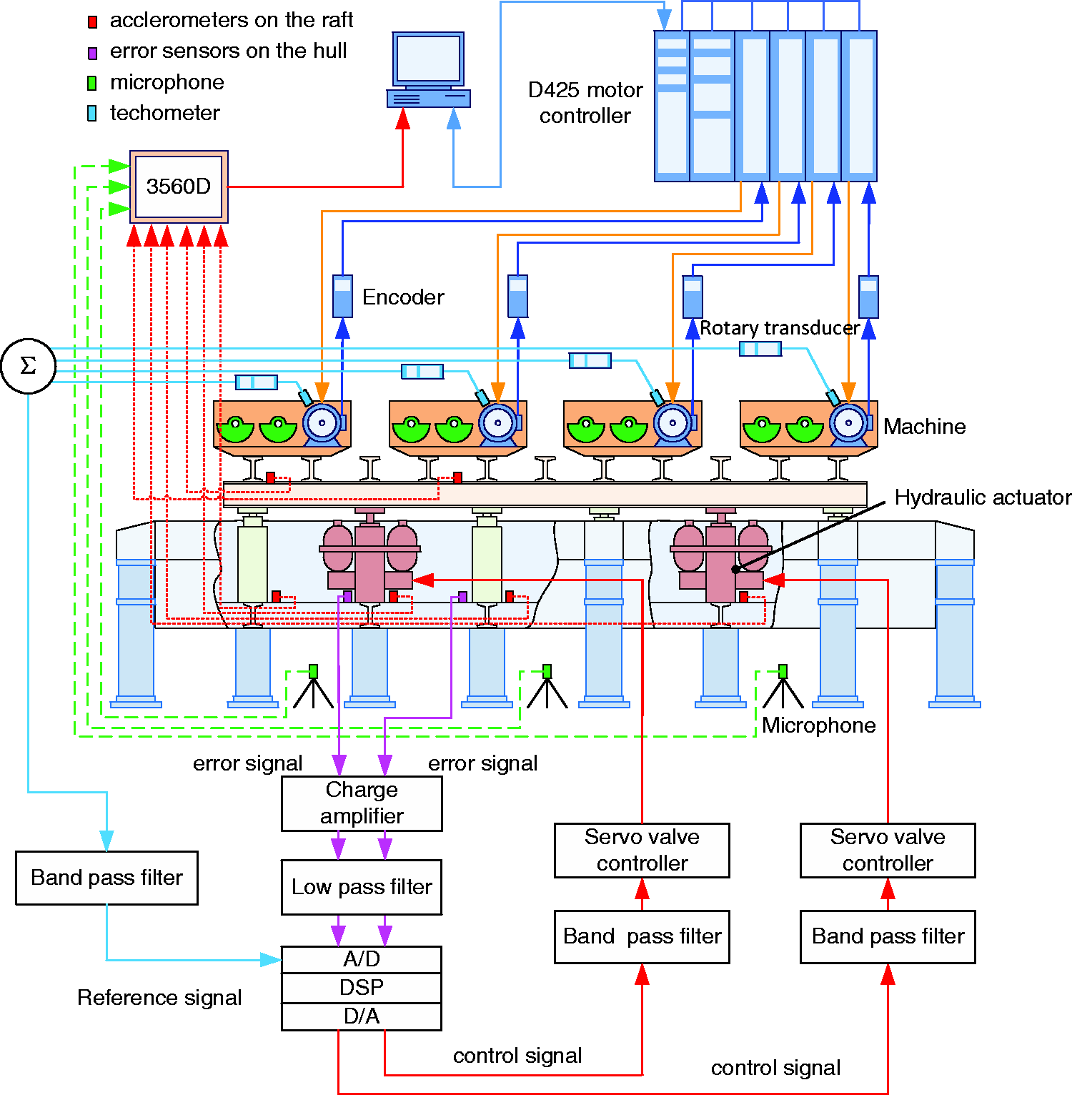
Schematic diagram of the experimental set-up showing the instrumentation and control system.
A detailed description of the synchrophasing method of vibration control is given by Yang et al.25,26 to which the reader is referred. A brief outline of the approach is given in Appendix 1. The active control system involved a standard adaptive feed-forward control approach as described in Yang et al.’s papers,8,27 and a brief outline of the approach is given in Appendix 2.
The active synchrophasing control procedure involved the following steps:
Experimental results and discussion
An experimental investigation was conducted with four machines working together at two different speeds. The effectiveness of the control approach was investigated for a wide range of speeds. Here, data for two speeds, at 1740 r/min and 3120 r/min, are presented to illustrate typical behavior. In the first case, the machines were operated at 1740 r/min, with the eccentric masses arbitrarily adjusted so that machines generated 1500 N, 1170 N, 1788 N, and 800 N respectively. In the second case, the machines were operated at 3120 r/min, generating 1381 N, 1098 N, 794 N, and 500 N, respectively.
Data were collected from the test-rig using the 6 accelerometers on the raft, the 22 accelerometers on the hull-like structure, and 10 microphones positioned outside the hull-like structure. The data were transformed to the frequency domain and the mean square of the sum of the acceleration responses and the mean square of the sum of the pressure responses were calculated. The experimental results are presented in Figures 4–6.
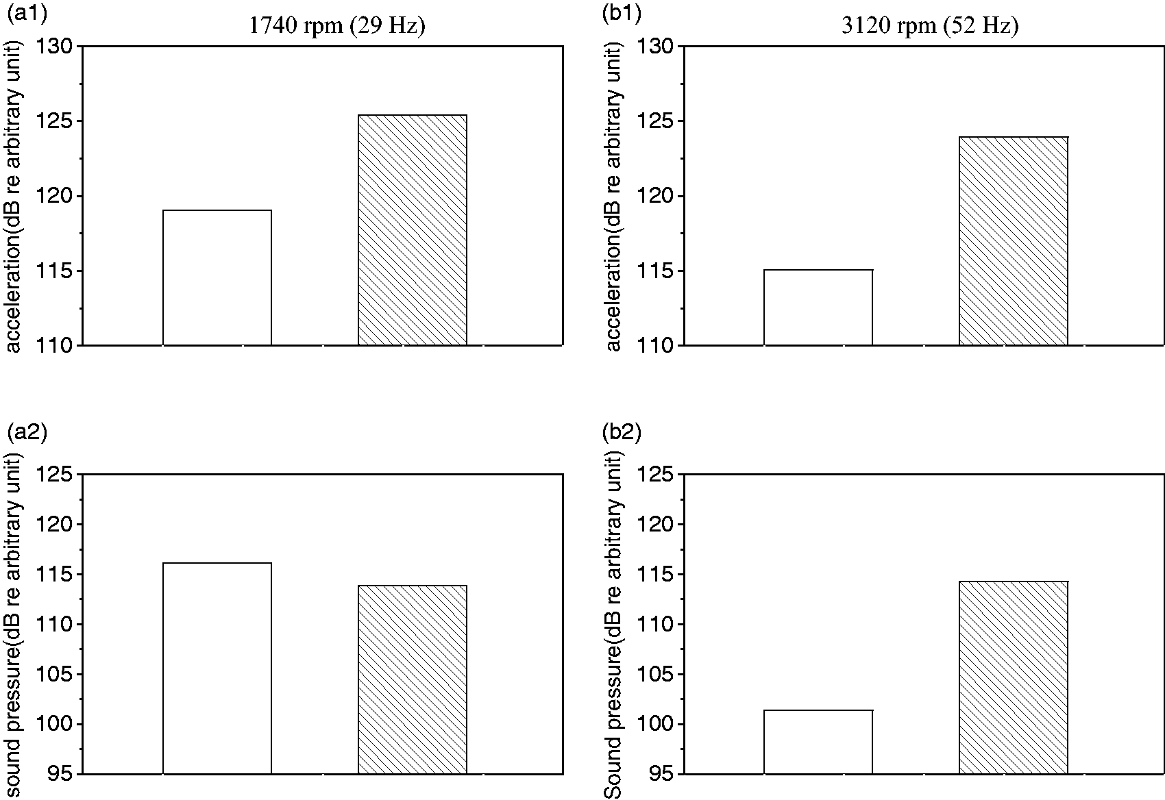
Experimental results of synchrophasing control, white bar: minimum and gray bar: maximum phase angles combinations. (a) Machine speed of 1740 r/min, (b) machine speed of 3120 r/min, (a1) acceleration cost function, (a2) sound pressure cost function, (b1) acceleration cost function, and (b2) sound pressure cost function.
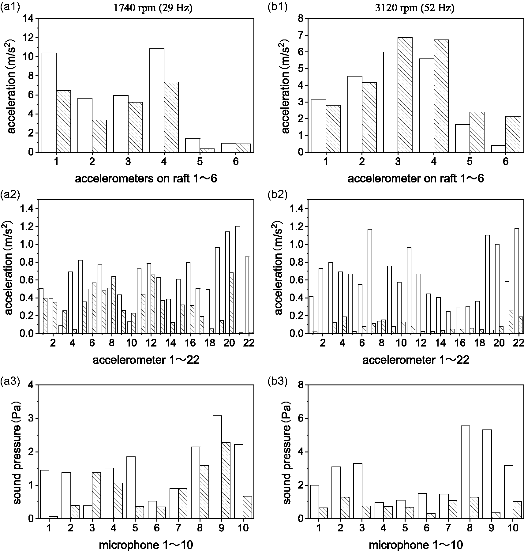
Outputs of sensors with and without active vibration control after synchrophasing control, white bar: without control shaded with control, (a) machine speed of 1740 r/min and (b) machine speed of 3120 r/min.
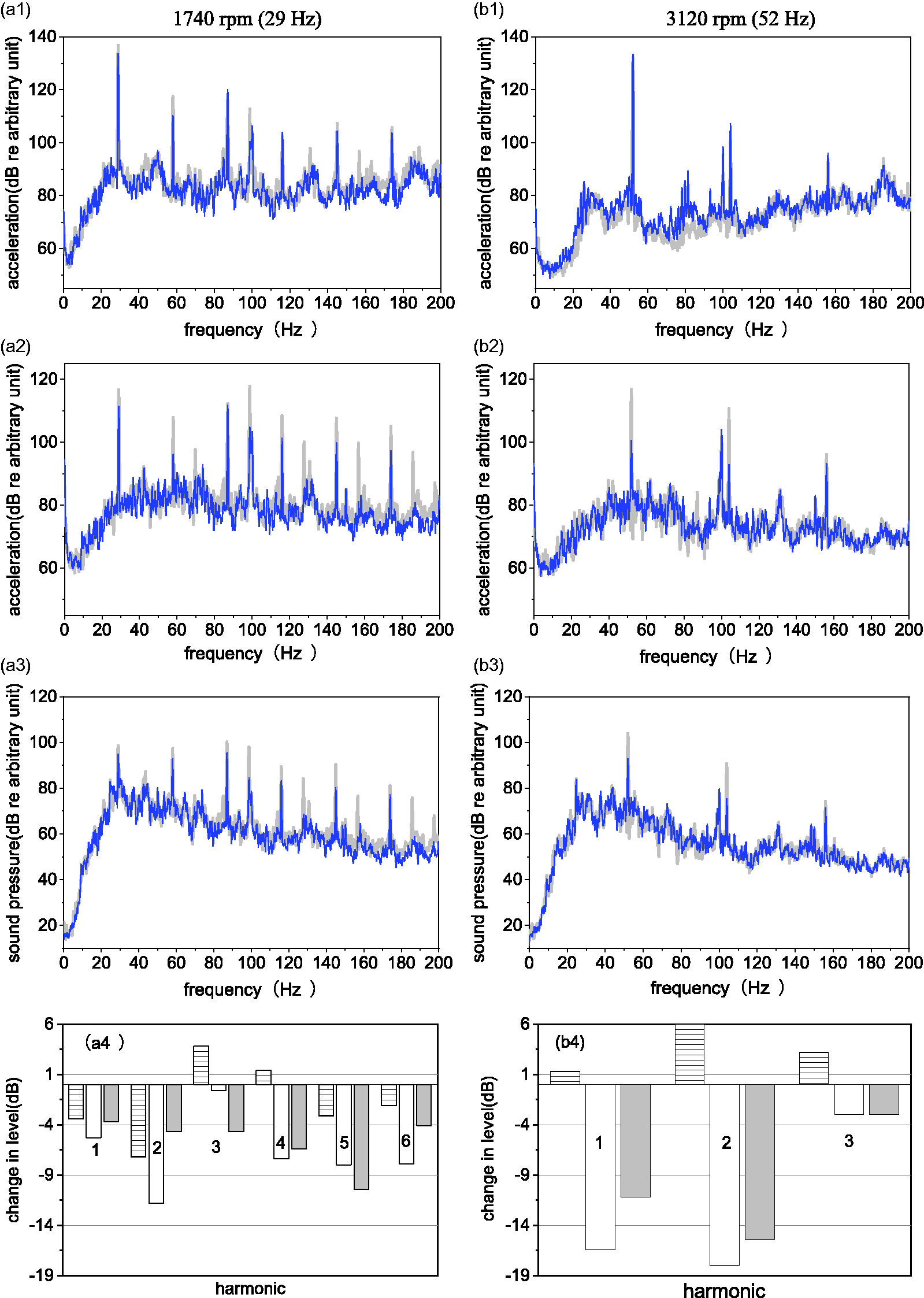
Vibration and sound reduction with and without active vibration control after synchrophasing control. Gray and thick line: without control, blue and thin line: with control. (a1 and b1) Raft vibration; (a2 and b2) hull-like structural vibration; (a3 and b3) sound pressure outside the hull, and (a4 and b4) changes at the harmonic frequencies in dB. Dashed box: raft vibration; white box: hull-like structure vibration; grey box: sound pressure level.
Figure 4 shows the results by synchrophasing control only. It can be seen that when the machines were operated at 1740 r/min, and when the phases were adjusted so that the vibration level was first a maximum and then a minimum, there was an overall difference in vibration level of the hull-like structure of about 6.4 dB. Interestingly, for this case, there was a corresponding increase of about 2.3 dB in the overall sound pressure level. Note, however, that the sound pressure level was not necessarily related to the sound radiated from the hull-like structure. It was a measure of the overall sound pressure level in the laboratory.
When the machines were operated at 3120 r/min, and when the phases were adjusted so that the vibration level was first a maximum and then a minimum, there was an overall difference in vibration level of the hull-like structure of about 8.9 dB. The corresponding change in overall sound pressure level was about 12.9 dB.
Following this experiment, the optimum phase combination to give the minimum vibration response of the hull-like structure was fed to the motion controller and the active control system turned on. Figure 5 shows the outputs of all the sensors with and without active vibration control following synchrophasing control.
Figure 5(a1) and (b1) shows that when the active control system was switched on, the vibration of the raft was reduced at every measurement point when the machines were operated at 1740 r/min, but generally increased when the machines were operated at 3120 r/min.
For the hull-like structure, whose data are shown in Figure 5(a2), good reductions can be seen at most measurement positions (except at positions 3, 6, and 8), when the machines were operated at 1740 r/min. It should be noted that four sensors at positions 4, 18, 21, and 22 were the error sensors, and the vibration levels after control at these positions are very low. The overall vibration reduction was about 5.3 dB. The corresponding sound pressure level is shown in Figure 5(a3), which shows that there were reductions at all positions except for position 3. The overall reduction in sound pressure level was about 3.8 dB.
When the machines were operated at 3120 r/min, the reduction in vibration of hull-like structure was excellent, except at position 8, as can be seen in Figure 5(b2). In this case, four sensors at positions 2, 5, 12, and 13 are the error sensors, and the vibration levels after control at these positions are very low. The overall reduction was about 16.4 dB. Corresponding reductions of the sound pressure at all positions were achieved, as can be seen in Figure 5(b3), with an overall reduction of about 11.1 dB.
In Figure 6, the performance of the active control and synchrophasing system is illustrated in terms of spectra. The mean square of the sum of the moduli of the accelerations on the raft, the hull-like structure, and sound pressures measured by the 10 microphones are shown in the frequency range 0–200 Hz. To help visualize the results, the changes in the overall levels at the harmonic frequencies are shown in Figure 6(a4) for an operational speed of 1740 r/min, and in Figure 6(b4) for an operational speed of 3120 r/min. Overall, it is clear that the combined system was very effective at suppressing the vibration of the hull-like structure and the sound pressure, with particularly good performance at the first and second harmonics for an operational speed of 3120 r/min.
Conclusions
This paper has described an experimental study into the vibration control of transmitted vibration from a machinery raft that houses four synchronous machines. As the machines are driven by electrical motors, the phases of the machines were adjusted prior to implementing an active control system to minimize the vibration transmitted to a hull-like structure and suppress the corresponding sound radiation. The results show that the combination of synchrophasing and active control is an effective way of reducing vibration transmission in a marine machinery installation.
Footnotes
Declaration of conflicting interests
The author(s) declared no potential conflicts of interest with respect to the research, authorship, and/or publication of this article.
Funding
The author(s) disclosed receipt of the following financial support for the research, authorship, and/or publication of this article: This work was funded by the National Natural Science Foundation of China (NSFC) under No. 51375103.