
Abstract
The frequency components of vibration signal in vibration isolation system under multiple excitations are quite complex.Self-adaptive feedforward control method based on Least Mean Square algorithm has strict requirements for reference signal, which results in a certain restriction on its practical application. Sliding mode variable structure control method needs neither complicated reference signal nor accurate mathematical model. It has the strong robustness for external disturbance and system parameter perturbation, and the physical implementation is simple. To this end, application of sliding mode variable structure control method is studied. First, mathematical model of the control channel through system is established for identification. Second, the discrete sliding mode variable structure controller based on state-space model is designed to carry out simulation and experiment. The experimental result indicates that root mean square value of vibration signal after control is decreased by 57.90%, of which the amplitudes of two main frequency components 17 and 25 Hz reduce by 42.66 and 72.71%, respectively. This shows that sliding mode variable structure control is an effective control method for active vibration isolation of floating raft under multiple excitations.
Keywords
Introduction
Mechanical noise is a main source of underwater radiation noise of submarine. Reducing the vibration of power plant can decrease the mechanical noise directly transmitted to water so as to enhance the concealment ability and fighting ability of submarine. The power plant of submarine is vibration isolation object with multiple complex excitations. The frequency components of vibration signal are usually very complicated. Although the traditional passive vibration isolation device can isolate broadband vibration effectively, the low-frequency vibration isolation ability is poor. Active control of vibration means introducing secondary vibration source to the controlled system in order to offset the primary vibration source. This technology can effectively reduce low-frequency vibration. 1 Consequently, it needs an active vibration control method which can effectively process multiple excitations to further reduce low-frequency vibration of submarine.
Self-adaptive feedforward control method based on LMS algorithm has such advantages as simple algorithm structure, easy implementation, and strong stability, so it has been studied extensively.2–6 Gao et al. 2 carried out experimental study on the cRIO real-time control platform through Fx-LMS self-adaptive filtering algorithm and realized active control of double-deck vibration isolation platform by adopting self-adaptive algorithm. By taking piezoelectric rod as the active component, Li et al. 3 constructed cube Stewart vibration isolation platform and adopted digital control system based on DSP and Fx-LMS self-adaptive algorithm for vibration control. Against periodic disturbance, An et al. proposed a nonlinear feedforward self-adaptive active vibration control algorithm based on maglev actuator. The algorithm could conduct self-adaptive compensation to maglev actuator nonlinearly and control the periodic disturbance. 4 Chen et al. 5 adopted self-adaptive feedforward method to the vibration isolation system of maglev vibration isolator for multifrequency active vibration isolation experiment. Prakash et al. 6 studied the application of LMS algorithm in practice and achieved good results.7,8 With regard to floating raft vibration isolation system, Chen 9 studied feedforward control by using Fx-LMS algorithm and pointed out the impact of sound feedback on reference signal in Fx-LMS algorithm. However, the self-adaptive feedforward control method based on LMS algorithm requires reference signal to be stable and known. The frequency components of reference signal in practical application are very complicated, and the stability is also poor under the impact of sound feedback, which results in the divergence of self-adaptive feedforward control method in practice. 9
Also, Sliding Mode Control (SMC) has been used for active control of vibration. The greatest difference from self-adaptive is that it belongs to feedback control. It does not need complicated reference signal, and the sound feedback problem does not occur. In practice, the algorithm does not need accurate mathematical model and has strong robustness for external disturbance and system parameter perturbation. Moreover, the physical implementation is simple. However, the current SMC research mainly focuses on active vibration control of elastic structure10–13 and microvibration precision platform with shock resistance as the purpose. 14 There are few experiments or studies that apply SMC to active vibration control of power plant for simulation.
By using the SMC method, this study conducted an active control experimental research on the vibration of multiple power plants. First, it erected active vibration isolation platform of floating raft with complicated multiple excitations. Second, a mathematical model of vibration isolation platform control channel was established. Third, discrete SMVS controller based on state-space model was designed to carry out simulation and experiment.
Active vibration isolation system of floating raft
The floating raft active vibration isolation test bed established in this paper is composed of two parts: mechanical device and electronic control device. The mechanical device of the floating raft active vibration isolator is shown in Figure 1. Two vibrating motors and two asynchronous motors are mounted on top of the two motor support plates in a skew-symmetric manner. As the disturbance source of active vibration isolator of floating raft, they can produce low-frequency external disturbance in operation. The two vibrating motors are connected to the frequency converter, and their rotational speed can be adjusted by the frequency converter in real time. Another two asynchronous motors are not connected to the frequency converter. The motor support plate is welded by steel plate and arranged on both sides of the raft with equal spacing. Eight small rubber isolators with the same size are installed between each motor support plate and the raft frame. Four large rubber isolators and four electromagnetic actuators are arranged symmetrically between the raft frame and the U-shaped base. Rubber isolator is a passive vibration isolator which can reduce the transmission of high-frequency vibration. As an active isolator, the amplitude, frequency, and phase of the control force output by the electromagnetic actuator can be adjusted to counteract the external low-frequency disturbance caused by the motor. The whole experimental device is fastened to the T-groove platform.
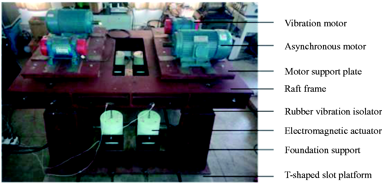
Mechanical device of active vibration isolation test bench for floating raft.
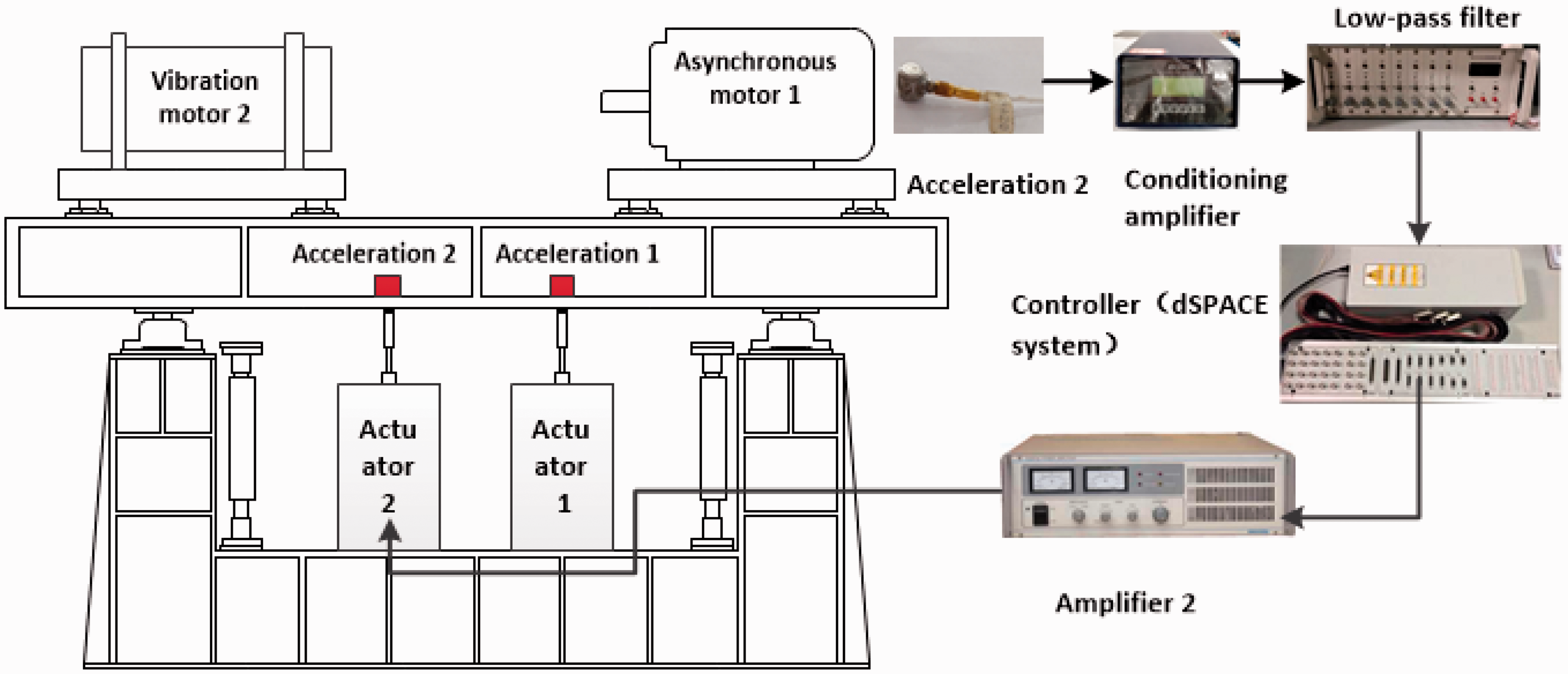
The electronic control device of the floating raft active vibration isolation test bed is as shown in Figure 2. It is composed of dSPACE1103 system, power amplifier, acceleration sensor, conditioning amplifier, low-pass filter, and signal generator. dSPACE1103 system consists of two parts: hardware and software. The hardware includes control board DS1103, wiring panel CLP1103, optical fiber line (orange red dual-port signal wire connected to the computer), real-time interface (embedded on the mainboard of the host), and upper computer. The software includes algorithm development software based on Simulink and application debugging software Control Desk. The acceleration signal collected by the acceleration sensor is processed by an amplifier and a low-pass filter, and output voltage signal is proportional to the acceleration. The voltage signal is collected by the A/D port of the dSPACE1103 system and the control signal is output through the D/A port. The control signal is amplified by the power amplifier and supplied to the electromagnetic actuator so as to output the corresponding control force to counteract the low-frequency external disturbance caused by the motor.
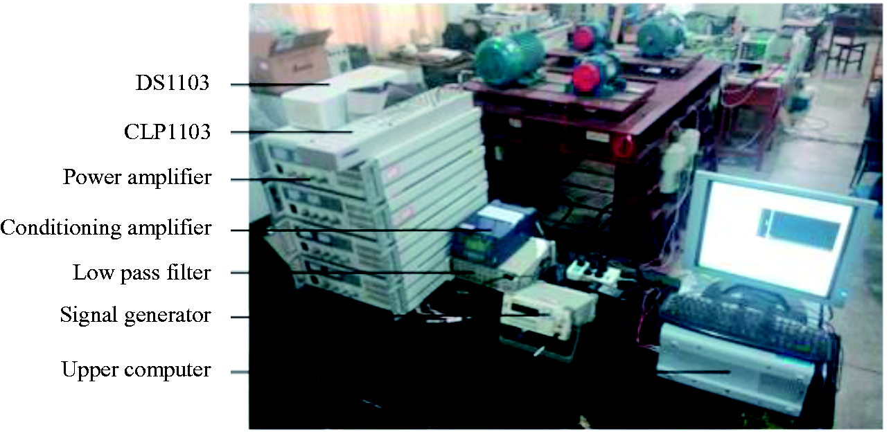
Electronic control device of active vibration isolation test bed for floating raft.
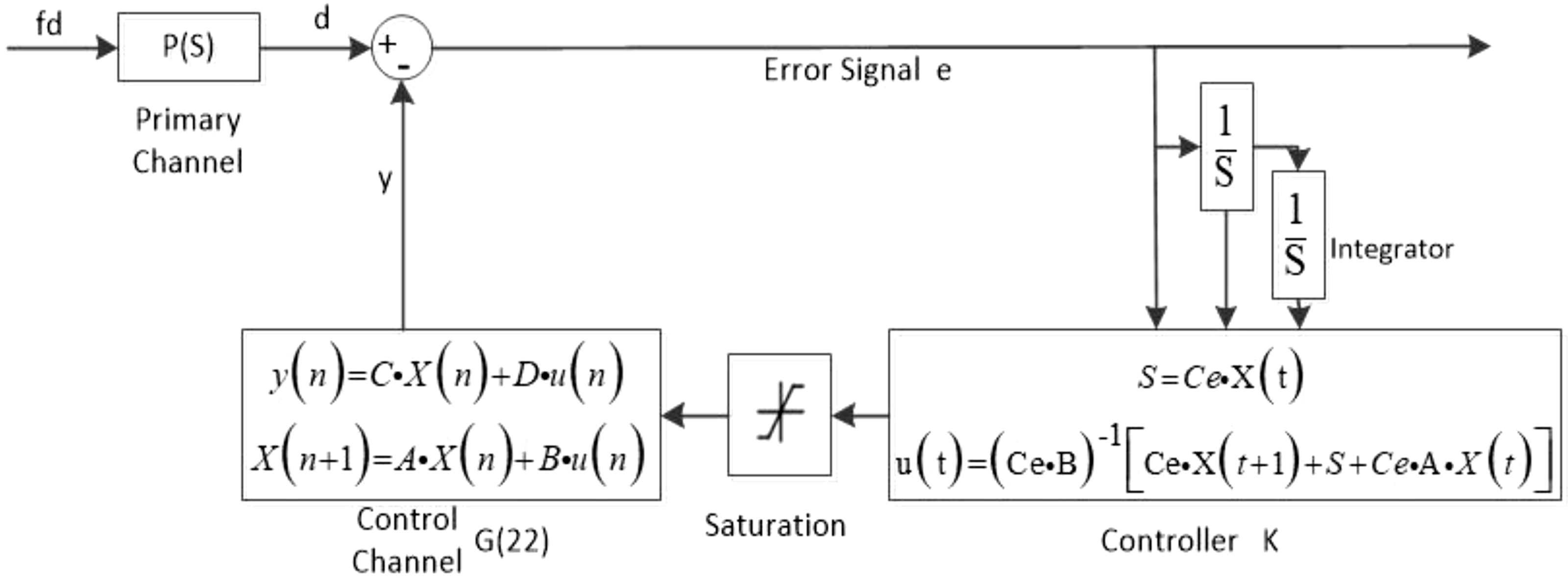
Figure 3(a) is the schematic diagram of feedback control by active vibration isolation system of floating raft, and Figure 3(b) is the feedback control block diagram of vibration isolation system of floating raft. f1, f3,…, fn is disturbing force produced by power plant. m1, m3,…, mn is the mass of power plant, m2 is the object mass put on the raft frame directly, c, c1, c3,…, cn is damping, k, k1, k3,…, kn is stiffness, and mR is the mass of raft frame. The acceleration signal of the vibration is measured by the sensor outputs control signal through controller K(s). Actuator outputs corresponding to control force fe to offset vibration are triggered by power plant. d in Figure 3(b) is the external disturbance signal, and primary channel P(s) is the transfer function of external disturbance force fd to signal d. Generally speaking, it is difficult to acquire, but it does not affect the design of feedback control system. K(s) is the controller, and u is the control signal output by controller. Signal y is the signal measured by the sensor when there is control but without external disturbance force fd and control channel. G(s) is the transfer function from control signal u to signal y.
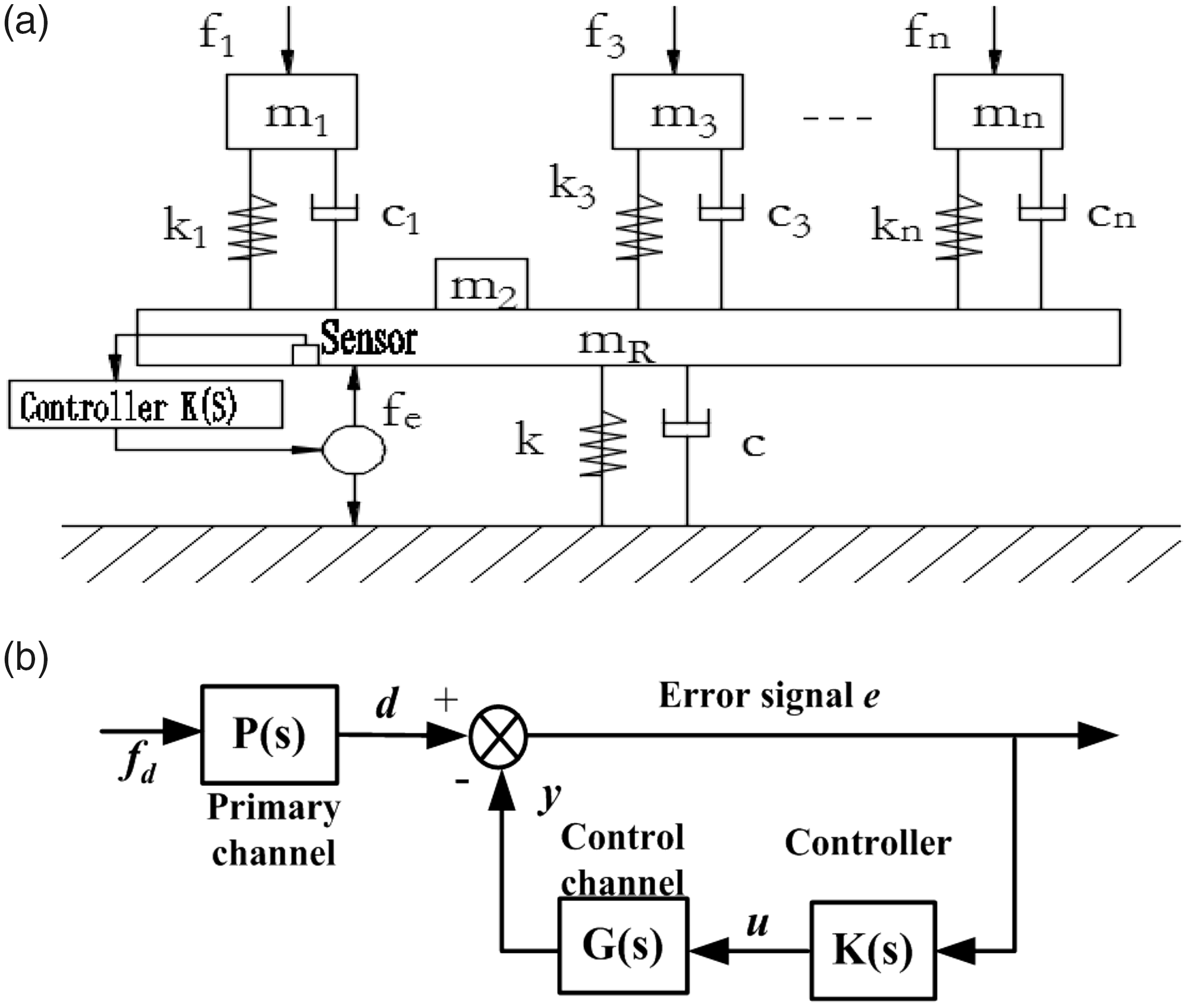
(a) Schematic diagram of feedback control by active vibration isolation system of floating raft and (b) feedback control block diagram of vibration isolation system of floating raft.
Model identification
Schematic diagram of identification
Schematic diagram of system identification experiment is shown in Figure 4. Four motors, four acceleration sensors, four actuators, and four amplifiers were labeled as 1#, 2#, 3#, and 4#, among which Motor 3# and 4# were at the right back of Motor 1# and 2#, Acceleration Sensor 3# and 4# were at the right back of Acceleration Sensor 1# and 2#, and Actuator 3# and 4# were at the right back of Actuator 1# and 2#. Acceleration sensor was connected to the corresponding channel of conditioning amplifier, and amplifier was connected to the corresponding actuator. 2, 3, 6, and 7 in the figure represents the channel no. of data acquisition analyzer. Channel 2# collected input voltage signal of Amplifier 2#, Channel 3# collected input voltage signal of Amplifier 3#, Channel 6 collected voltage signal of Acceleration Sensor 2# after conditioning and filtering, and Channel 7# collected voltage signal of Acceleration Sensor 3# after conditioning and filtering.
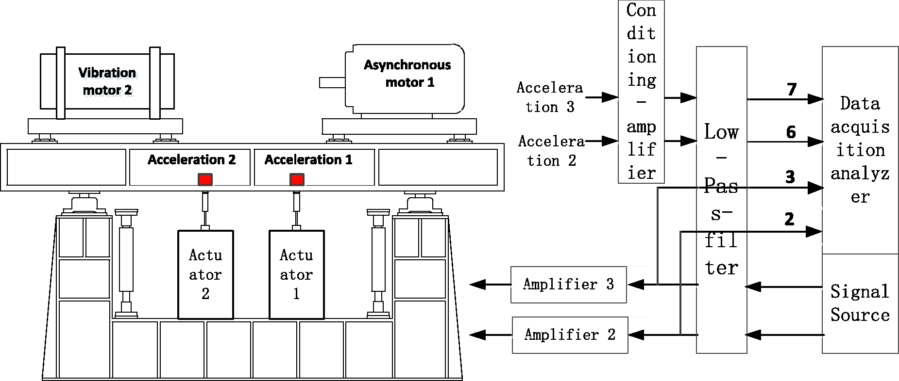
Schematic diagram of system identification experiment.
Model identification and verification of control channel
Designing a successful controller needs a mathematical model which can accurately describe dynamic characteristics of the controlled object. The controlled object mentioned in this paper refers to the control channel of active vibration isolation system of floating raft, namely the transmission channel from control voltage signal output by the controller to error signal input to the controller. Owing to the complexity of control channel, it is difficult to establish an effective mathematical model through mechanism. To this end, this paper establishes a mathematical model by adopting frequency domain identification method.
As one of the classical nonparametric model identification methods, spectral analysis can accurately estimate the frequency characteristics of the controlled object according to the input and output data of the controlled object. Spectral analysis method has various advantages, such as simple theory, strong reliability, easy realization, and strong ability to suppress noise and obtain accurate frequency response function. Therefore, this paper adopts spectral analysis to estimate the frequency characteristics of the plant under control. Spectral analysis can only obtain the frequency response of the controlled object, that is the nonparametric model of the controlled object. The design of sliding mode variable structure controller needs a mathematical model of controlled object which is expressed by state-space equation in the analysis and design of control system. This requires to transform the nonparametric model into a parametric model by calling the system identification toolbox in MATLAB software.
The frequency response function of the control channel is calculated automatically according to the input and output, and the frequency response function is input into the MATLAB system identification toolbox. The stable discrete transfer function can be identified by using the function tfest (). The discrete transfer function is transformed into the form of spatial state space equation by calling tf2ss () to obtain
The floating raft studied in this paper is used to suppress the vibration of ship power machinery. In practice, the main frequency component of the vibration signal is in the range of 10–50 Hz. 15 According to the main frequency range of the disturbance signal in the experimental device, the frequency range of 15–70 Hz is selected as the effective frequency response data to analyze the frequency characteristics of the controlled object.
If the motor does not work, an effective value 1.5 V white noise would be provided to power amplifier of actuator. The input signal of actuator power amplifier and the output signal of low-pass filter are measured through data collection and analyzer. The cutoff frequency of the filter is 70 Hz, the sampling frequency is 750 Hz, and the sampling time is 10 s.
The floating raft active vibration isolation system has four control channels: G22, G23, G32, and G33. Taking the control channel G22 as the control object, the model obtained through identification is fitted to the experimental data, and the result is as shown in Figure 5. From the figure, it can be seen that the model can accurately describe the dynamic characteristics of control channel within the frequency range of 15–70 Hz. Frequency domain degree of fitting and time domain degree of fitting are the evaluation indexes of system identification tool box and the values are 92.9 and 90.3%, respectively. In addition, the first three-order inherent frequencies of active vibration isolation system of floating raft are 17.4, 25.4, and 45.1 Hz.
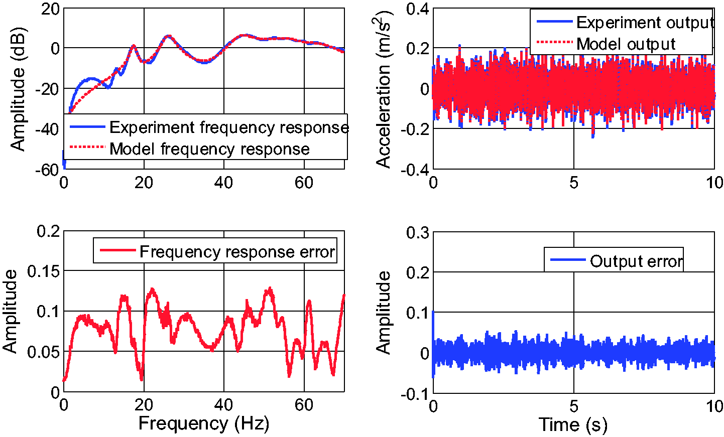
Control channel G22 model and experimental data fitting diagram.
Hereinto
Discrete sliding mode variable structure control (SMVSC) based on reaching law
Controller design
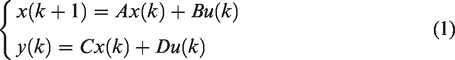
Specific to 10-order discrete system G22
From the perspective of control, controlling the vibration response of active vibration isolation system of floating raft can inhibit the impact of external disturbance on system. The control aims to make the system reach zero state under the effect of control input when the system state departs from the balance state for some reasons. In other words, the design of active vibration controller is the design of state regulator. 13
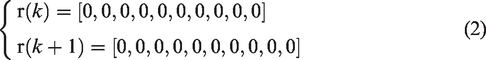
Suppose r(k) is the reference value of vibration signal, let
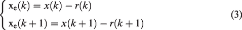
Define error signals Xe(k) and Xe(k + 1) at k and k + 1 as
According to structure vibration and control objective, suppose the switching function s(k) and s(k + 1) of system at k and k + 1 can be supposed
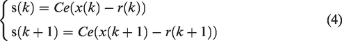
Hereinto, Ce is the coefficient on the sliding mode surface and Ce=[c1,c2,c3,…,c9,1]. It can guarantee the asymptotic stability of sliding mode motion and rapid dynamic response.In sliding mode control, parameters c1,c2,c3,…,c9 should meet that the polynomial p9+c9p8+···+c2p+c1 is Hurwitz, of which p is Laplace operator.
Substituting formula (1) into formula (4), we can obtain

According to formula (5), we can obtain the control law

Reaching law method is a typical control strategy in discrete SMC. Through this method, the system can monotonously reach the switching surface within the limited paces, so that the overall state-space has a good quality movement.
16
We adopt index reaching law to design discrete sliding mode controller. The discrete reaching law can be expressed as

Hereinto, constant Ts is the sampling period; eq is the velocity of system motion point reaching the switching surface s = 0; sgn () is a symbol function; and q is the index reaching item parameter, which mainly affects the dynamic transition process of switching function.
Substitute formula (7) into formula (6) to obtain the discrete control input voltage based on index reaching law

To control buffeting of controller and the limit of input voltage, saturation function sat(s(k)) is adopted to substitute sgn(s(k)) in formula (8)
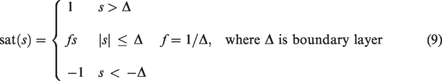
Switching control was adopted outside the boundary layer. Within the boundary layer, linear feedback control was adopted. The control input voltage expressed in formula (8) becomes

Stability proof
Select Lyapunov function
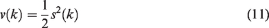
As long as it meets the condition

According to stability theorem of Lyapunov function, it is known that the balance surface of global asymptotic stability is s(k)=0, that is the final value reaches the switching surface s(k) no matter what the initial state value is. Consequently, the reaching condition is

When the sampling period Ts is very small, the existence and reaching condition of discrete sliding mode are
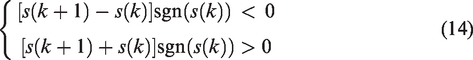
However, when

In the meantime, when adopting time Ts is very small and
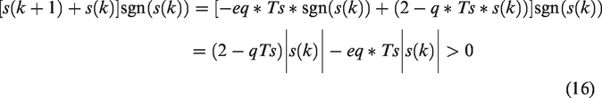
Consequently, when discrete reaching law formula (8) meets the reaching condition, it can ensure the reaching law modality has good quality.
Control simulation and experiment
Control simulation
In Simulink, the SMVSC simulation system model of inhibitive double-frequency fluctuation disturbance is as shown in Figure 6. Hereinto, G22 is control channel model and K is inhibitive double-frequency fluctuation disturbance SMVS controller. The simulation time is 15 s. In simulation, interference signal fd is about 1 Hz doublet swept-frequency signal including double frequency around a certain frequency (namely dominant frequency), which are 17 and 25 Hz, respectively.
SMVSC simulation system model of inhibitive double-frequency fluctuation disturbance.
For discrete SMVS controller based on reaching law, it is important to select q, eq, and Ce. For Ce, the coefficient on sliding mode surface Ce reaches 10, which can hardly be adjusted. Therefore, they are further simplified. We select three coefficients in the simulation process and set the latter coefficients as 0. That is to say, considering the error signal, the primary integral, and the secondary integral of error signal and ignoring differential and multiorder differential of error signal, we find that the influence of differential and multiorder differential is very small in the parameter adjustment process. Suppose the first three coefficients are a1, a2, a3, and let a1=λ2, a2=λ, a3=1. Thus, the acquired coefficient meets the condition that a1p2+a2p+a3 is Hurwitz. To make the control signal

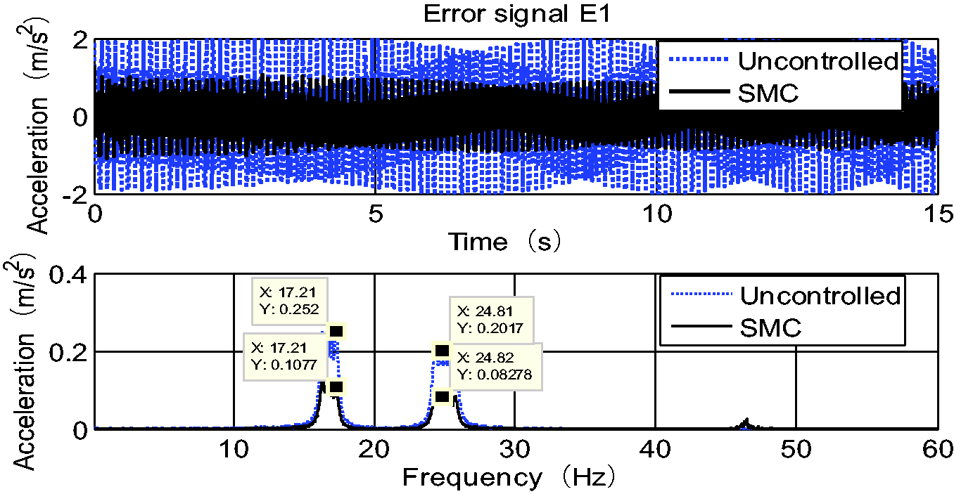
Acceleration–time diagram and spectrogram with dominant frequencies 17 and 25 Hz. SMC: Sliding Mode Control.
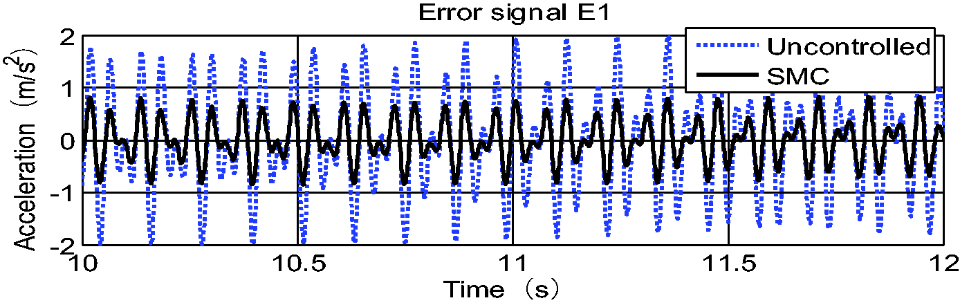
Enlarged acceleration–time view. SMC: Sliding Mode Control.
The acceleration–time diagram and spectrogram with dominant frequencies 17 and 25 Hz are shown in Figure 7. According to the acceleration–time diagram, for simulation, the acceleration error signal E1 at Acceleration Sensor 2# reduces by about 60% after sliding mode control. According to spectrogram, the amplitude at 17.21 Hz attenuates by 57.26% and amplitude at 24.81 Hz declines by 58.96%. Figure 8 shows the enlarged acceleration–time view.
Control experiment
The multiple excitations vibration isolation system of floating raft is shown in Figure 9. As the disturbance source, the vibration motor provides single-frequency external disturbance signal. Vibration motor connected with frequency converter can adjust the rotation. Disturbance force (from vibration motor) and control force (form actuator) overlap at the joint and the acceleration signal triggered by the produced resultant force is monitored by the sensor. The output signal of sensor passes the conditioning amplifier and the low-pass filter and gets the output voltage signal directly proportional to acceleration. The voltage signal can be deemed as error signal E, and the output port of filter is connected to A/D port of wiring panel CLP1103 of dSPACE1103 system. As the controller hardware, control panel AS1103 can compute the controlled variable according to the designed controller. After D/A transition, the controlled variable outputs control signal U. To avoid the case in which big control signal results in the damage of power amplifier because of the large output current of power amplifier, the amplitude of control signal must be restrained. The restrained amplitude range is −5 to 5 V. After passing by the amplifier, the control signal drives the electromagnetic actuator to output corresponding control force so as to offset the vibration caused by vibration motor.
Experimental schematic diagram of active vibration isolation of floating raft.
When the rotation of Vibration Motor 2# was 1500 r/min and the rotation of Vibration Motor 3# was 1020 r/min, active vibration control experiment was conducted according to Figure 9. The experiment results are shown in Figures 10 and 11. Figure 10 is the time domain diagram of error signal and control signal. From the time domain diagram, it can be seen that the control signal before control is 0 and the amplitude of error signal is about 0.7. When the control starts, the control signal gradually increases to a stable state. The error signal reduces correspondingly and tends to reach a stable state. The amplitude of error signal decreases sharply after control. To cut out 0–5 s in the figure as the error signal before control and 25–30 s as the error signal after control, root mean square (RMS) values of error signal before and after control are 0.6720 and 0.2829, and RMS value decreases by 57.90%. Figure 11 is the spectrogram when the rotations of two motors are 1500 and 1020 r/min. The amplitude nearby 17 Hz declines by 42.66% and the amplitude nearby 17 Hz declines by 72.71%.
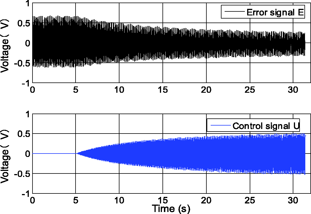
Control result when motor rotations are 1500 and 1020 r/min.
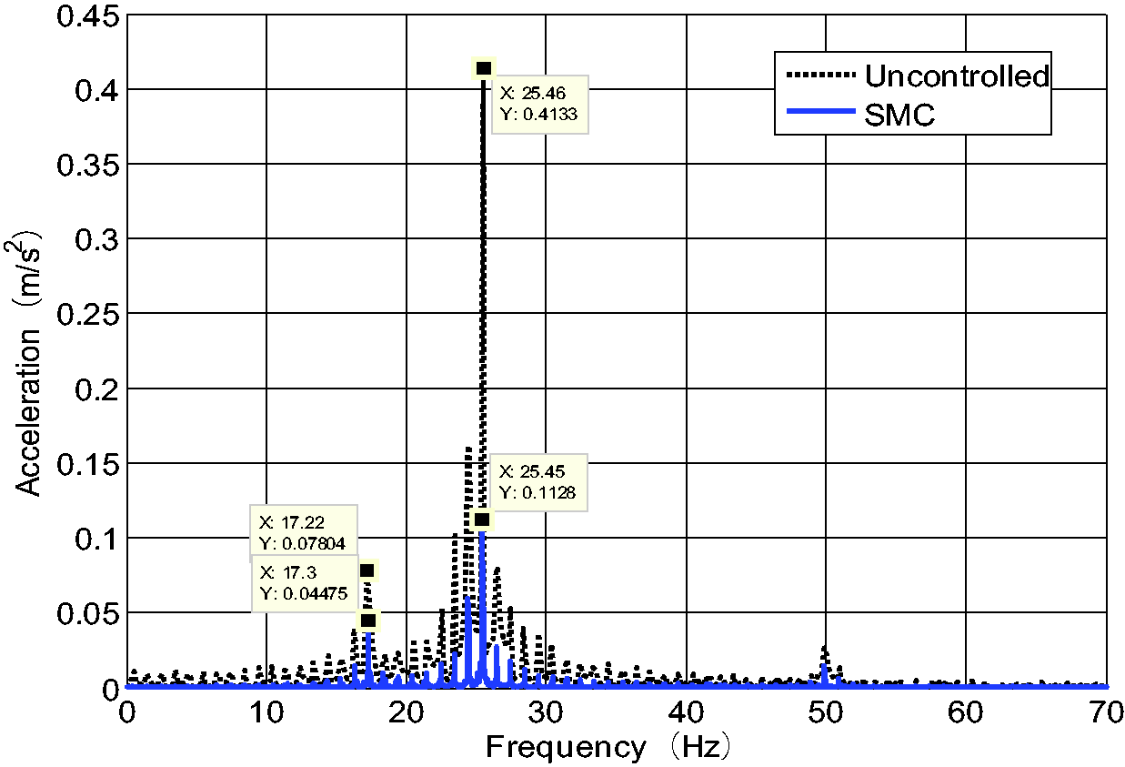
Spectrogram when motor rotations are 1500 and 1020 r/min. SMC: Sliding Mode Control.
Conclusions
Multisources excitation active vibration isolation system has complex structure and strong coupling ability. For those features, this paper established a control channel mathematical model based on the frequency domain identification method by using the MATLAB system identification toolbox for the floating raft system under multiple excitations. On this basis, the discrete sliding mode variable structure controller based on spatial state model was designed, and the simulation analysis of multisources excitation active vibration isolation system and the corresponding experiment verification were carried out. According to the experimental results, when the active vibration isolation control was applied in floating raft system, the RMS value of vibration signal decreased by 57.90%, the amplitudes of the main frequency components 17 and 25 Hz in vibration signals decreased by 42.66 and 72.71%, respectively. This shows that sliding mode variable structure control is an effective control method for active vibration isolation of floating raft under multisources excitation.
Footnotes
Declaration of conflicting interests
The author(s) declared no potential conflicts of interest with respect to the research, authorship, and/or publication of this article.
Funding
The author(s) disclosed receipt of the following financial support for the research, authorship, and/or publication of this article: This research was supported by National Natural Science Foundation of China ((No.51275368, No. U1537103 and No. 51775400).