
Abstract
To determine the effect of rotor eccentricity on the vibration of multistage pumps, a five-stage centrifugal pump with vaned diffusers was selected to experimentally measure the vibration characteristics under both stable condition and unstable condition due to the rotor eccentricity. The results show that the rotor eccentricity results in an irregular orbit of the rotor axis, which is diffused outward. As the flow rate increases, the peak amplitude of the rotor axis’ orbit first decreases and then increases, and the peak amplitude at the design flow rate is minimized. The main vibration frequencies of rotor axis’ orbit are the axis passing frequency and a secondary high frequency. After rotor eccentricity occurs, all monitoring point vibrations increase by different degrees, the increments of axial vibration are particularly obvious, and the characteristic frequencies of the pump increase.
Keywords
Introduction
Multistage centrifugal pumps are widely used in architecture, hot water circulation, coal mine emergency drainage, sewage treatment, petrochemicals and other fields. Many scholars have investigated multistage centrifugal pumps. Wilson et al. 1 analyzed the effects of viscosity and two phases, namely, liquid and gas fluids, on a multistage electrical submersible pump and obtained a series of curves representing the pump performance degradation. Cui et al. 2 numerically analyzed the unsteady radial force in multistage centrifugal pumps with double volute and investigated the relevance of static pressure, radial force and radial vibration. Babayigit et al. 3 studied the effect of balance holes and leakages (clearances) on the performance of a multistage pump. Wang et al. 4 proposed a method to optimize the design of a typical multistage centrifugal pump based on an energy loss model and computational fluid dynamics (CFD). Jiang et al. 5 constructed five diffusers with different axial widths based on the area ratio principle. Tan et al. 6 experimentally investigated the effects of the clocking effect on the performance and vibration intensity of a five-stage centrifugal pump. Shibata et al. 7 studied the diffuser rotating stall, observed positive Q-H characteristics and elucidated the mechanism of positive-slope generation. Wang et al. 8 studied the influence of impeller blade thickness on the performance of stainless steel multistage centrifugal pumps and analyzed the whole flow field with different blade thicknesses. Huang et al. 9 employed a sliding mesh technique to investigate transient flow fields and pressure fluctuations in a multistage diffuser pump. Salvadori et al. 10 proposed a numerical evaluation method for the residual axial thrust in multistage centrifugal pumps. Babayigit et al. 11 numerically analyzed the effects of the blade exit angle change on the hydraulic efficiency of a multistage pump impeller for constant width impeller entrance and exit gates, blade numbers and blade thickness. Wang et al. 12 designed four diffusers with different inlet structures to match the characteristics of the diffuser to the impeller.
Multistage centrifugal pumps are becoming increasingly high-power and high-speed and thus require better operation stability. An eccentric rotor will have unstable pump operation in the long term, which may cause bearing wear and cracks on the rotor surface. Therefore, it is very important to study the operating characteristics of multistage centrifugal pumps experiencing eccentricity. Some scholars have investigated rotor eccentricity. Tabatabaei et al. 13 used a modified winding function theory to simulate a salient-pole synchronous generator and obtained stator and rotor winding distribution with dynamic eccentricity between the stator and rotor. Zhu et al. 14 adopted a nonlinear finite element method to calculate the no-load branch voltage waveform of a synchronous generator with an eccentric rotor and skewed stator slots. Dorrell et al. 15 provided a new theory to analyze the interactions between harmonic field components due to static and dynamic rotor eccentricity in three-phase induction motors.
Vibration is a significant feature after rotor eccentricity occurs. Therefore, scholars have researched the vibration characteristics of multistage centrifugal pumps. Wang et al. 16 experimentally measured the vibration characteristics of a five-stage pump under noncavitation condition and cavitation condition and analyzed the effect of cavitation on pump vibration. Moreover, they 17 measured the pressure pulsation, vibration and noise of the five-stage centrifugal pump at different flow rates. Lu et al. 18 studied the axis orbit and vibration spectrum of a cantilever multistage centrifugal pump at zero flow rate, the design flow rate and a large flow rate. Zhang et al. 19 presented a method for rolling bearing fault diagnosis based on variational mode decomposition and investigated the simulated vibration signal of the proposed fault model by fast Fourier transform (FFT) and envelope analysis. Wang et al. 20 adopted fractional oscillators to deal with noise in the vibration. Ren et al. 21 proved that residual calculations between the frequency and amplitude of a nonlinear oscillator could be further simplified without losing accuracy.
However, research on multistage centrifugal pump operating characteristics when experiencing rotor eccentricity is still inadequate. To provide a reference for the further study on operating characteristics under rotor eccentricity, the effect of rotor eccentricity on the vibration of a five-stage centrifugal pump with vaned diffusers at different flow rates was analyzed.
Test device and energy characteristics experiment
Test bench
The design parameters of the five-stage centrifugal pump with vaned diffusers are as follows. Flow rate Qd is 100 m3/h, head H is 165 m, rotation speed n is 1480 r/min, and specific speed ns is 65.4 (
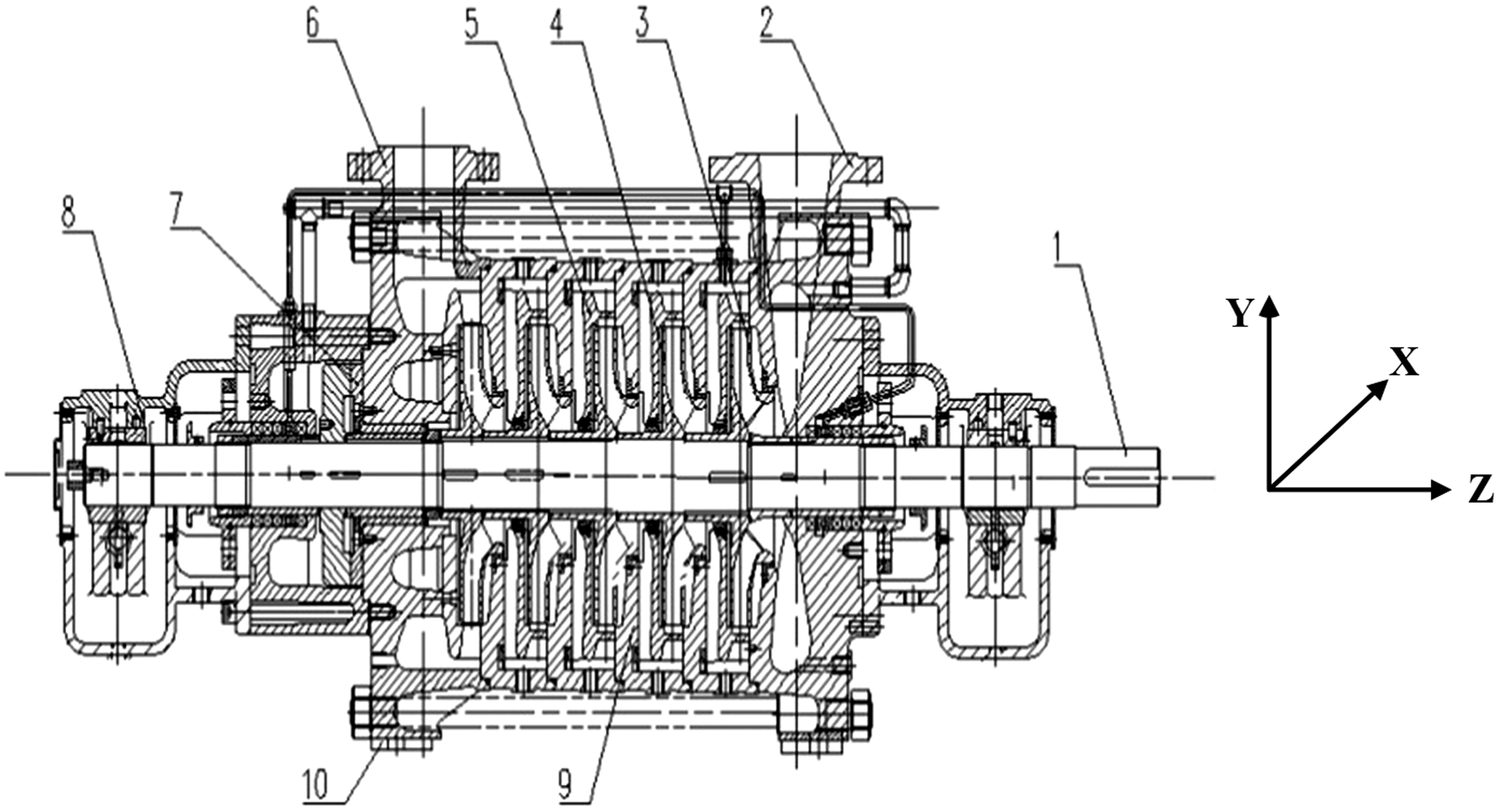
Structure of a five-stage centrifugal pump. 1. Shaft. 2. Suction section. 3. First-stage impeller. 4. Second-stage impeller. 5. Vaned diffuser. 6. Discharge section. 7. Balance disc. 8. Bearing seat. 9. Middle part. 10. Pump foot.
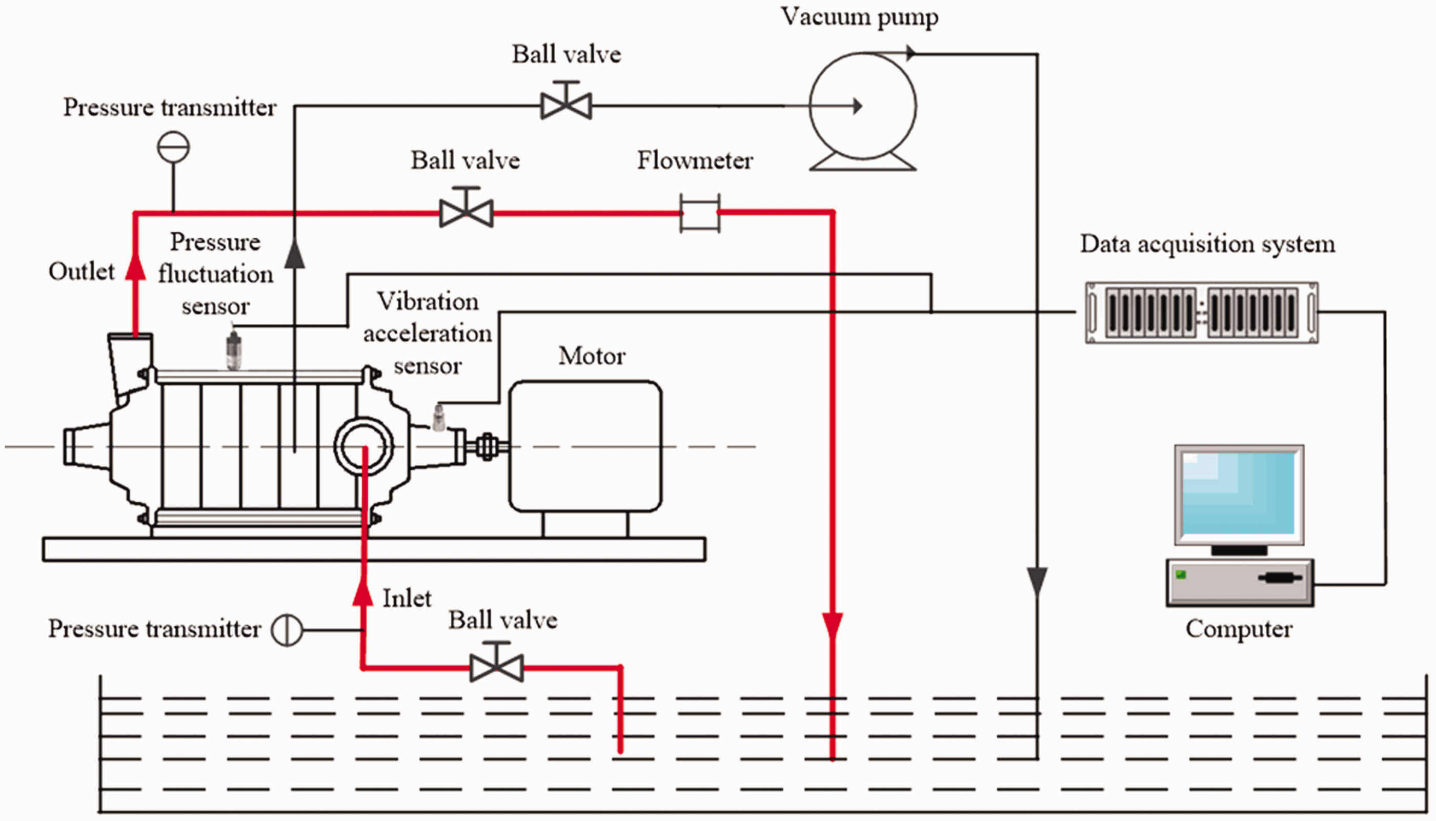
Schematic of the five-stage centrifugal pump test.
Energy characteristics experiment
Figure 3 shows the energy characteristics experiment curves of the five-stage centrifugal pump with vaned diffusers. It can be seen from Figure 3 that, at the design flow rate, the head is 165.4 m and the efficiency is 72.8%. The maximum efficiency point is at 1.1Qd, where the head of the pump is 161.03 m and the efficiency is 74.06%.
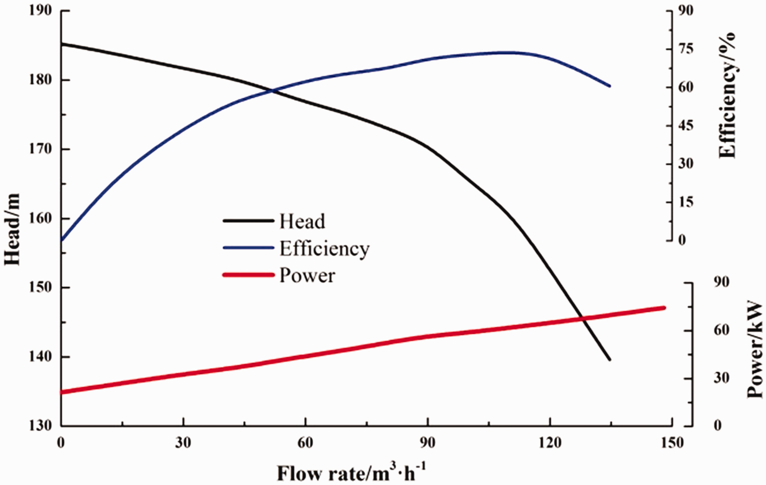
Energy characteristic curves of the pump.
Test instruments
In this experiment, an eddy current sensor which is a noncontact linear displacement measuring sensor, mainly composed of a front end device, an extension cable and a probe, obtained rotor axis’ orbit displacement value data. It measures the change in distance between the metal object and the end of the probe, and processes it into an electrical signal.
The INV9832 piezoelectric three-axis acceleration sensor was adopted to measure the vibration of the five-stage pump. The INV3020C system was used to collect the vibration signals. The sampling frequency was 12.8 kHz and the sampling time was 40 s.
Distribution of monitoring points and data processing method
Distribution of the rotor axis’ orbit sensors
The pump shaft rotor axis’ orbit is in a two-dimensional plane. Therefore, two sensors need to be installed on the same plane of the pump shaft to collect data. To attach and adjust the sensors, a sensor fixing bracket was made that adjusts in any direction to measure vertical and horizontal axial orbits. The sensor fixing bracket is installed on the pump block with a magnetic base. Figure 4 is a picture of the rotor axis’ orbit sensor location near the bearing at the connection between the pump and the motor. The horizontal and vertical eddy current displacement sensors are arranged to obtain the horizontal and vertical displacement value for rotor axis’ orbits with time. In this experiment, the distance between the probe and the pump shaft is 1 mm.
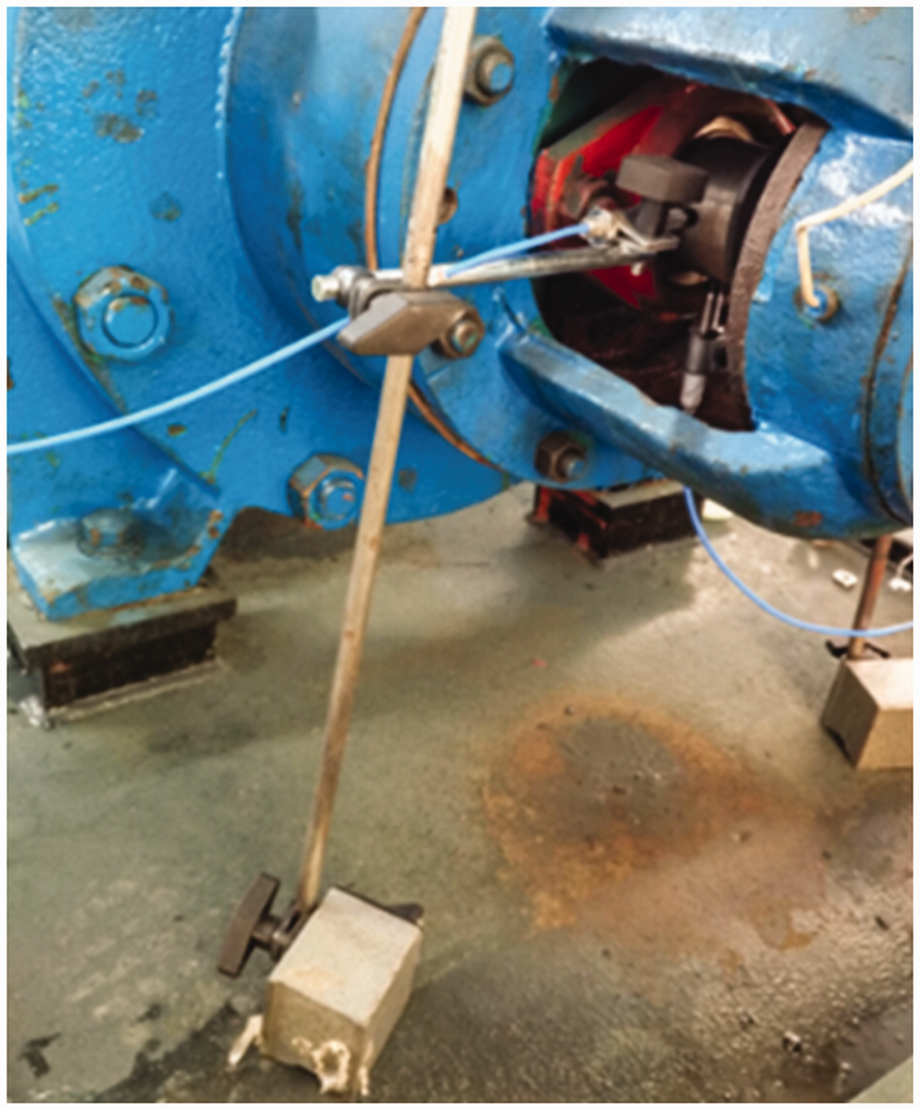
Location of rotor axis’ orbit sensors.
Distribution of vibration monitoring points
The vibration measurement method in the manuscript follows the Chinese standard “Pump vibration measurement and evaluation method (GB/T29531-2013)”. Six vibration monitoring points (V1–V6) were set in this experiment. The bearing near the outlet of the five-stage pump was defined as B1, and the bearing close to the coupling of the five-stage pump was defined as B2. The monitoring point V1 was located at bearing B1, and V2 was located at bearing B2. Monitoring points V3 and V4 were located in the inlet and outlet flanges of the pump, respectively, V5 (near the outlet of the pump) and V6 (near the coupling of the pump) were located on the two symmetrical pump feet. Figure 5 shows the monitoring points V2, V4 and V5, where the sensors were magnetically mounted.
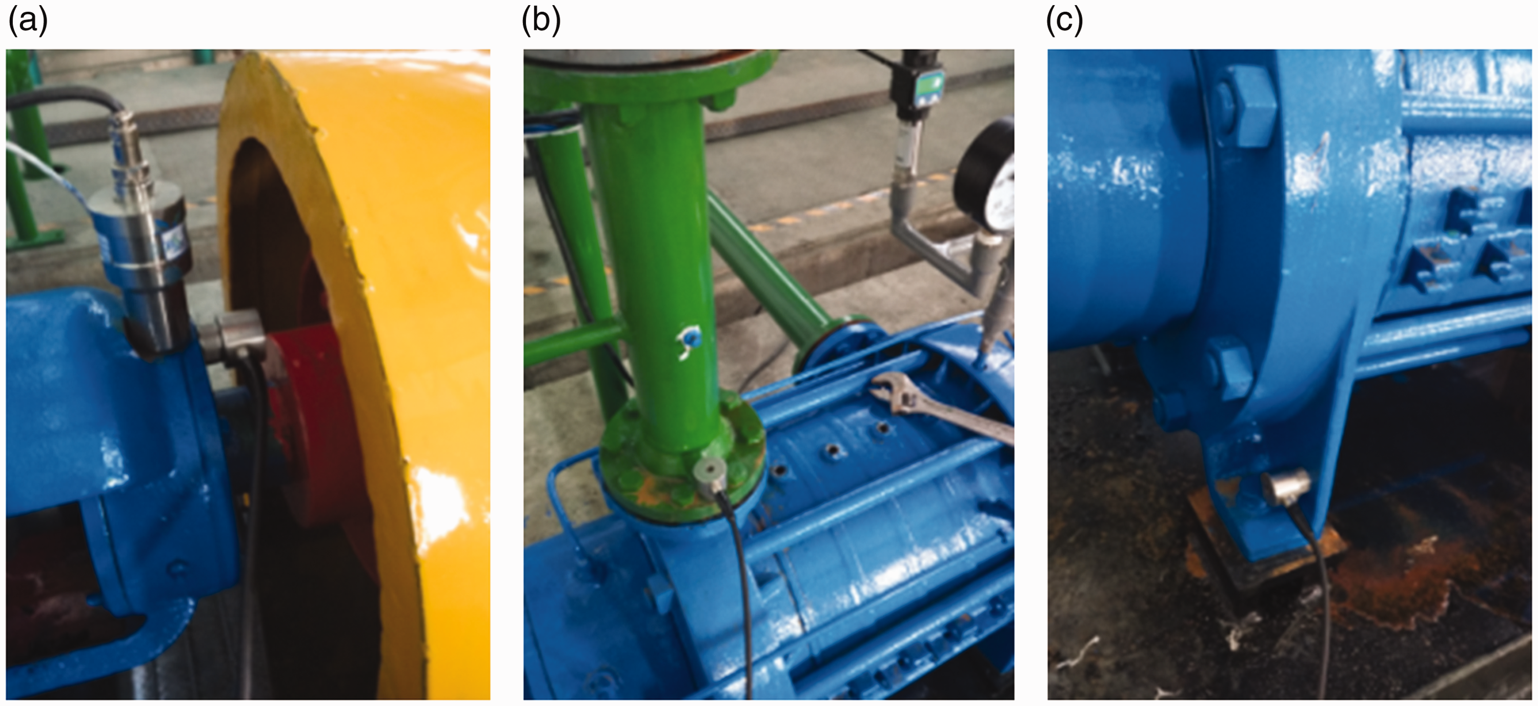
Distribution of monitoring points. (a) V2. (b) V4. (c) V5.
Data processing method
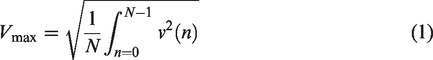
Vibration acceleration was integrated into vibration velocity by the integral function in the Distributive Analysis Stata Package (DASP) software. The time domain diagram of the rotor axis’ orbit and vibration signals was converted into a frequency domain diagram by Fourier transformation. Vibration velocity was defined as the root mean square of vibration velocity to evaluate the level of overall vibration. The calculated value of vibration intensity Vmax can be obtained by the following equation
Results and analysis
Rotor axis’ orbits
Stable condition
Figure 6 shows the rotor axis’ orbit of the five-stage centrifugal pump under stable conditions. It can be seen that the shapes and sizes of the rotor axis’ orbit at 0.6Qd, 0.8Qd, 1.0Qd and 1.2Qd are similar indicating that the rotor is running smoothly. Notice that, the rotor axis’ orbit is elliptical and counterclockwise at different flow rates, which indicates that the rotor has a certain dynamic unbalance fault.
Rotor axis’ orbit under stable conditions. (a) 0.6Qd. (b) 0.8Qd. (c) 1.0Qd. (d) 1.2Qd.
Figure 7 shows the time domain of the rotor axis’ orbit in the five-stage centrifugal pump under stable conditions. It can be seen that the waveforms at 0.6Qd, 0.8Qd, 1.0Qd and 1.2Qd in the X and Y directions are periodic sinusoidal waves, the glitch characteristics are minimal, and the phases of the X- and Y-direction time domains are exactly 1/4 cycle apart. At 1.0Qd and 1.2Qd, the peak amplitudes of the rotor axis’ orbit in the X and Y directions are not very different indicating that the hydraulic excitation causing shaft vibration is not large at these stages. This is because the pump rotor installation is good, and the eccentric excitation is small. From 1.0Qd to 0.8Qd and then at 0.6Qd, the peak amplitude of the rotor axis’ orbit in the X direction increases from 42.29 μm to 43.34 μm, an increase of 2.48% and in the Y direction it increases from 39.52 μm to 42.70 μm, or 8.05%. The turbulence of the corresponding rotor axis’ orbits also gradually increases. These results indicate that pump operation at low flow rates increases the vibration of the shaft system.
Time domain characteristics of rotor axis’ orbit under stable conditions. (a) X direction. (b) Y direction.
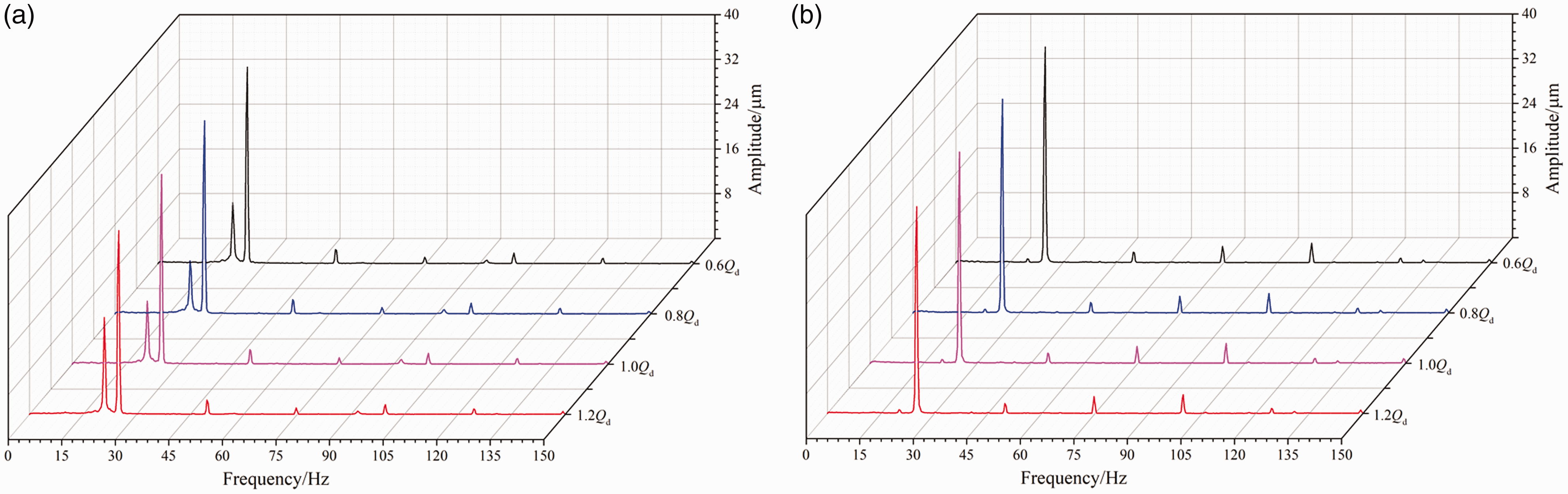
Figure 8 shows the frequency spectrogram of the rotor axis’ orbit in the five-stage centrifugal pump under stable conditions. In the frequency range from 0 to 150 Hz, the main frequency of the rotor axis’ orbit vibrations at 0.6Qd, 0.8Qd, 1.0Qd and 1.2Qd is the axis passing frequency (APF), and the amplitudes at 2APF, 3APF, 4APF are small. For 1.0Qd and 1.2Qd, the rotor axis’ orbit amplitudes of 1APF in the X and Y directions are not very different. From 1.0Qd to 0.8Qd, and from 0.8Qd to 0.6Qd, the axial orbit amplitude of 1APF in the X and Y directions increases with decreasing flow rate.
Frequency spectrogram of rotor axis’ orbit under stable conditions. (a) X direction. (b) Y direction.
Unstable condition due to the rotor eccentricity
To study the five-stage centrifugal pump rotor axis’ orbit under rotor eccentricity, the motor rotor axis was set parallel but 0.75 mm away from the pump axis.
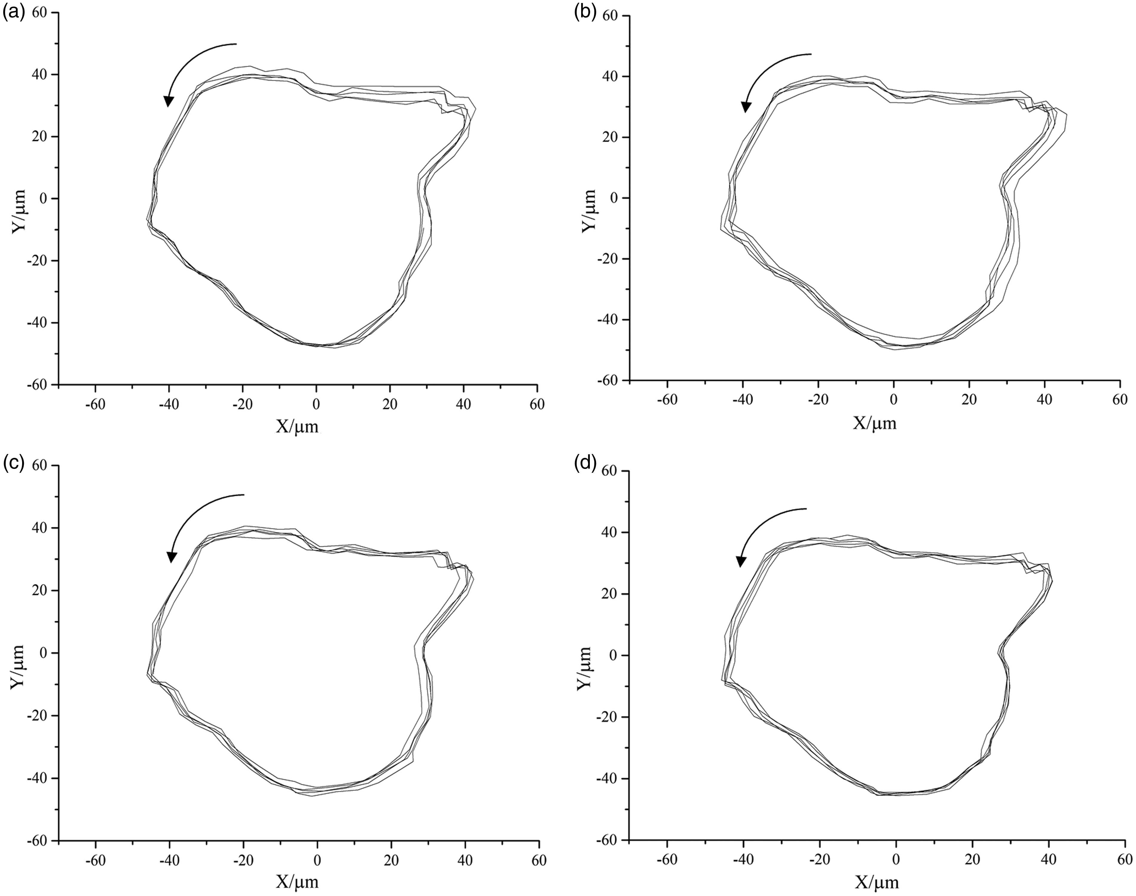
Figure 9 shows the rotor axis’ orbit of the five-stage centrifugal pump under unstable condition due to the rotor eccentricity. It can be seen that the rotor axis’ orbits at 0.6Qd, 0.8Qd, 1.0Qd and 1.2Qd are irregular and in a clockwise direction, which is opposite the orbit direction under stable conditions. Additionally, the five-stage pump has a power frequency vibration caused by the unbalanced rotor it runs. In addition, the rotor axial orbit at 0.6Qd, 0.8Qd, 1.0Qd and 1.2Qd is outwardly diffused, and the rotor axial orbit contour first increases and then decreases with increasing flow rate. The rotor axis contour trace is the smallest at the design flow rate, which may be due to the dynamic friction between the rotor and the bearing, as the mechanical vibration and noise generated by the five-stage pump during operation influence the rotor axial orbit in unstable condition due to the rotor eccentricity.
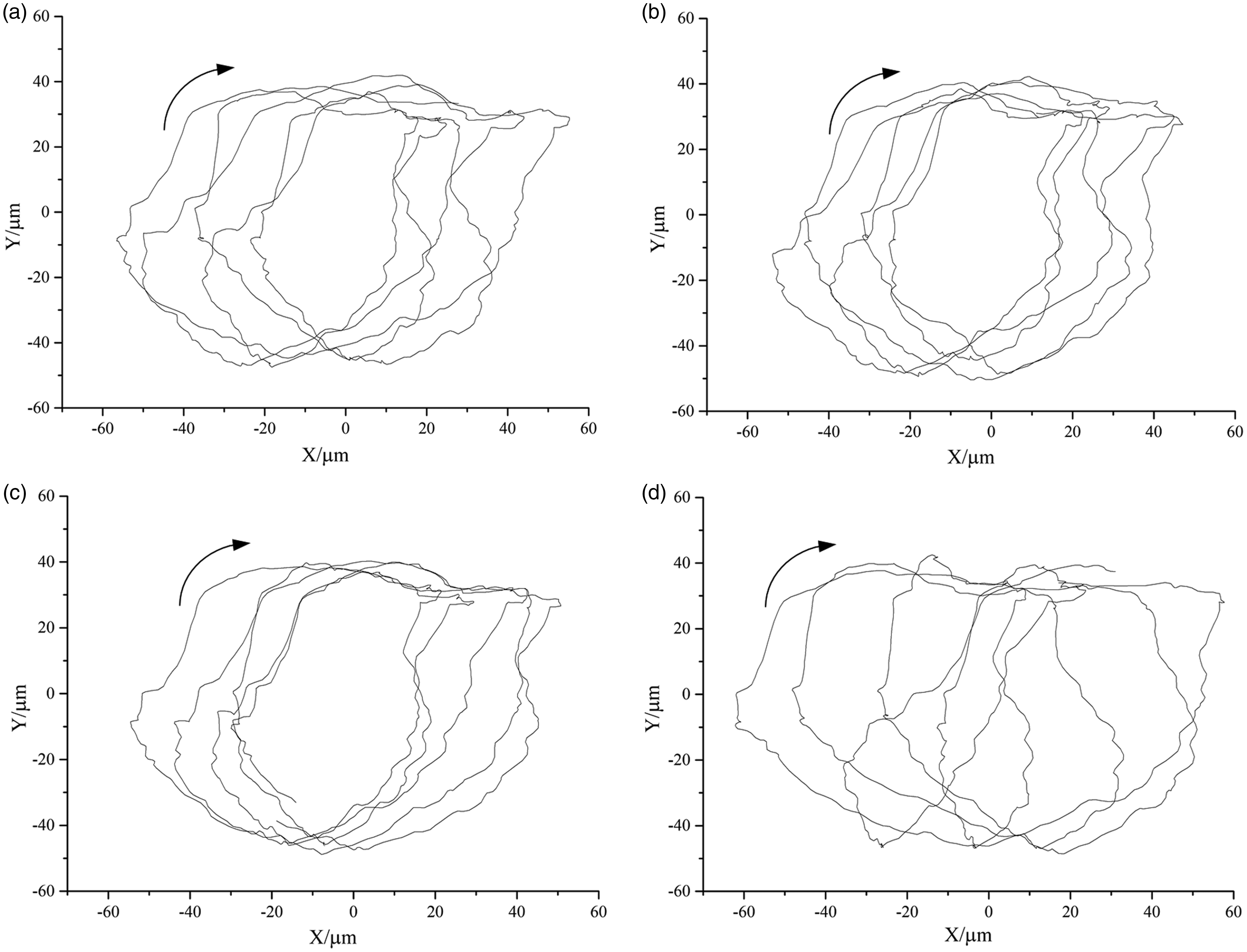
Rotor axis’ orbit under unstable conditions due to the rotor eccentricity. (a) 0.6Qd. (b) 0.8Qd. (c) 1.0Qd. (d) 1.2Qd.
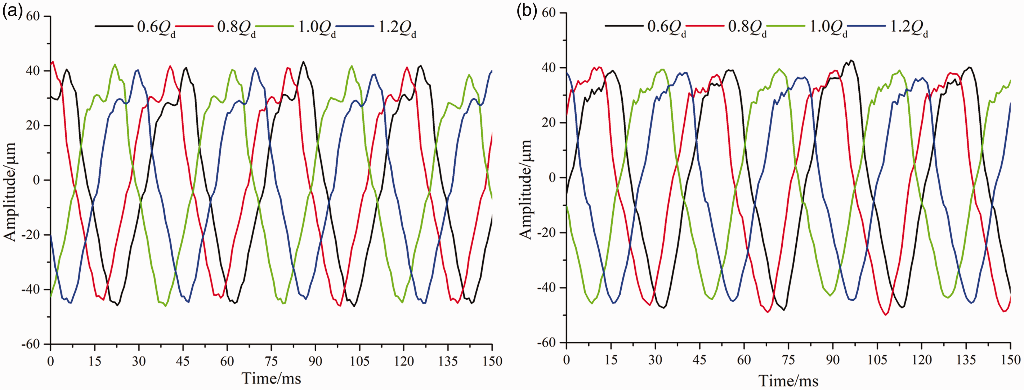
Figure 10 shows the time domain of the five-stage centrifugal pump under unstable conditions due to the rotor eccentricity. It can be seen that the waveforms of the rotor axial orbit in the X and Y directions at 0.6Qd, 0.8Qd, 1.0Qd and 1.2Qd are periodically distorted sine waves characterized by many small fluctuations. At 1.0Qd and 1.2Qd, as the flow rate increases, the peak amplitude of the rotor axial orbit in the X direction increases from 50.74 μm to 51.04 μm, and in the Y direction it increases from 40.13 μm to 42 μm indicating that the power frequency vibration caused by an unbalanced rotor at this stage gradually increases with increasing flow rate. From 1.0Qd to 0.8Qd and 0.6Qd, as the flow rate decreases, the peak amplitude of the rotor axial orbit in the X direction increases from 50.74 μm to 55.30 μm, or 8.9%, and in the Y direction it increases from 40.13μm to 41.92 μm, or 4.46%. This is because during low flow rates, there are a series of large-scale vortices such as backflow and secondary flow inside the five-stage pump. Medium-high frequency excitation forces caused by these unstable flows aggravate the power frequency vibration of the rotor.
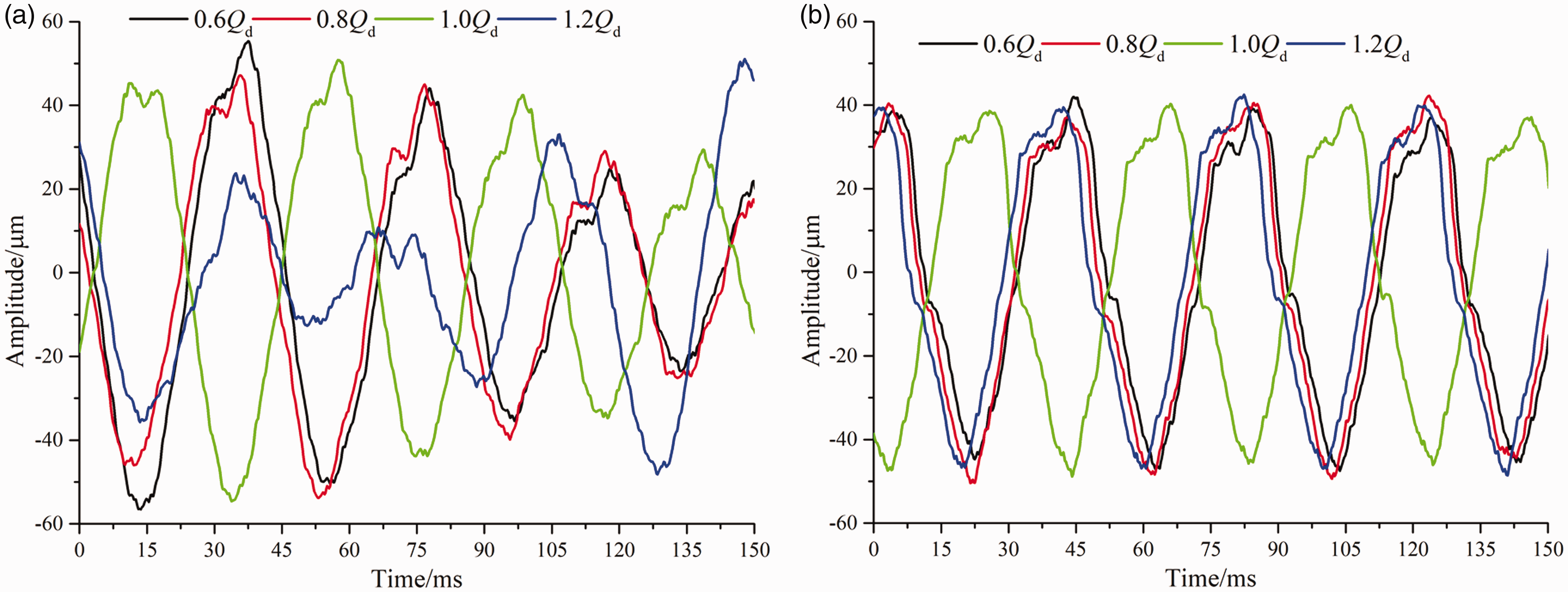
Time domain characteristics of rotor axis’ orbits under unstable conditions due to the rotor eccentricity. (a) X direction. (b) Y direction.
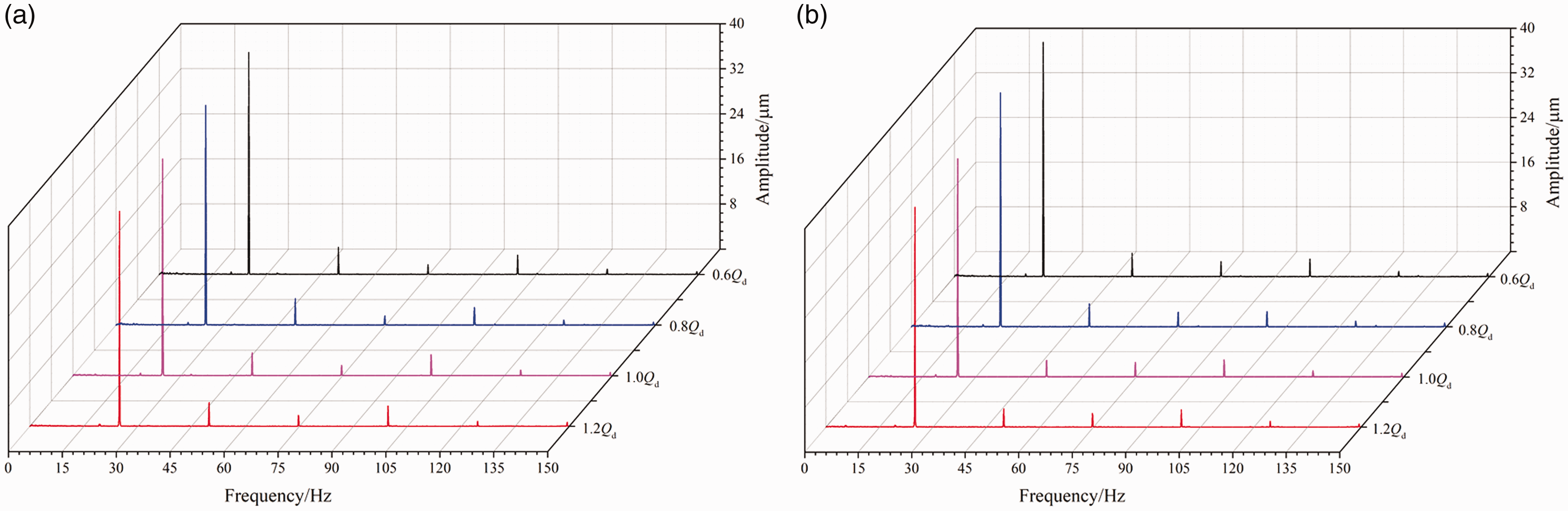
Figure 11 shows the frequency spectrogram of the rotor axis’ orbit of the five-stage centrifugal pump under unstable conditions due to the rotor eccentricity. In the frequency range from 0 to 150 Hz, at 0.6Qd, 0.8Qd, 1.0Qd and 1.2Qd, the main frequencies of the rotor axial orbit in the X direction are at 1APF with two spikes in amplitude, and in the Y direction the vibration is at 1APF. From 1.0Qd to 1.2Qd, the peak amplitude of the main frequency of the rotor axial orbit in the X and Y directions increases with increasing flow rate. From 1.0Qd to 0.8Qd, and 0.6Qd, the axial orbit amplitude of 1APF in the X direction increases from 33.87 μm to 35.11 μm, or 3.84%. The axial orbit amplitude of 1APF in the Y direction increases from 37.71 μm to 38.59 μm, or 2.33%.
Frequency spectrogram of rotor axis’ orbit under unstable conditions due to the rotor eccentricity. (a) X direction. (b) Y direction.
Vibration characteristics
Vibration characteristics at 0.6Qd
To study the relationship between frequency and the APF, a dimensionless frequency number NF (NF is the ratio of frequency to the APF) is introduced. Figure 12 gives the vibration velocity spectrogram of monitoring points V1 through V6 at 0.6Qd under stable condition and unstable condition due to the rotor eccentricity. It can be interpreted from Figure 12 that vibration velocity amplitudes of all the monitoring points from 0 to 300 Hz increase to some degree, and the main frequencies of monitoring points V1 and V2 are both 7APF. When rotor eccentricity occurs, the main frequency peaks of monitoring point V1 in the horizontal, vertical and axial directions increase by 0.095 mm/s, 0.02 mm/s and 0.048 mm/s respectively, and the main frequency peaks of V2 in the corresponding directions increase by 0.067 mm/s, 0.61 mm/s and 0.073 mm/s, respectively. The vibration intensities of the other monitoring points are smaller than those for monitoring points V1 and V2.
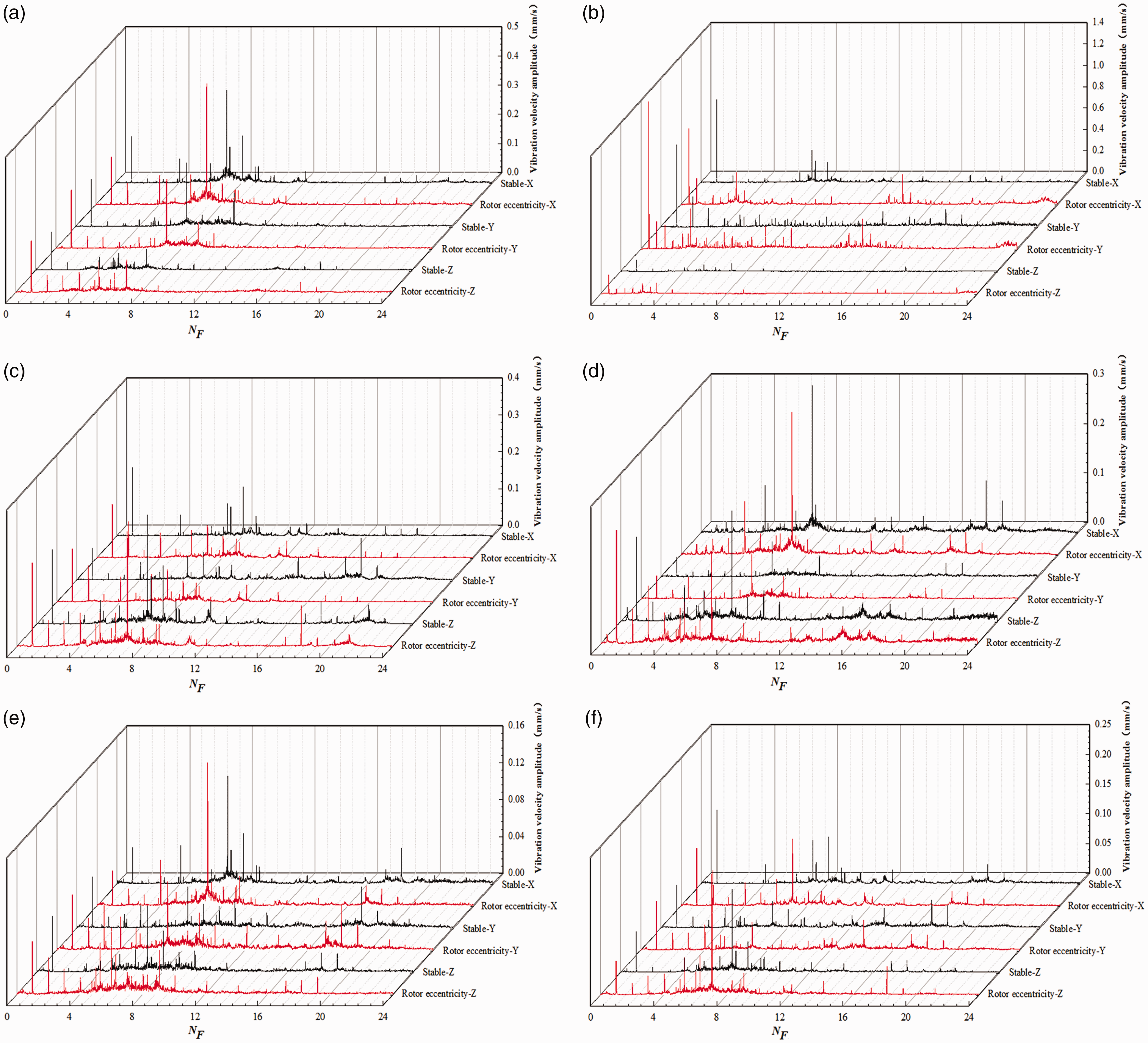
Vibration velocity spectrograms at 0.6Qd. (a) V1. (b) V2. (c) V3. (d) V4. (e) V5. (f) V6.
Vibration characteristics at 0.8Qd
Figure 13 gives the vibration velocity spectrograms of monitoring points V1 through V6 at 0.8Qd under stable condition and unstable condition due to the rotor eccentricity. In Figure 13, after rotor eccentricity occurs, the main frequency of monitoring point V2 at 0.8Qd is APF and main frequencies of other monitoring points are APF and 7APF. This shows that rotor unbalance, rotor eccentricity and vibration induced by rotor-stator interaction between the secondary impeller and vaned diffuser are the main sources of vibration in the five-stage pump. Monitoring point V2 is located at bearing B2, and the influence of rotor eccentricity on the vibration is obvious. By comparing the stable condition and unstable condition due to the rotor eccentricity at 0.8Qd, it is evident that the increments of vibration velocity for monitoring points V2 and V3 under unstable conditions are correspondingly larger than those under stable conditions. The main frequencies of monitoring point V2 in the horizontal, vertical and axial directions are all APF, and main frequency peaks in the corresponding three directions under unstable condition increase by 0.054 mm/s, 0.55 mm/s and 0.064 mm/s, respectively. In addition, the other characteristic frequency peaks are not observable. The main frequencies of monitoring point V3 in the X, Y and Z directions are APF, APF and 7APF, respectively, and Z direction vibration is obviously larger than that in the X and Y directions. The vibration velocities of the main frequency peaks in the three corresponding directions increase by 0.021 mm/s, 0.037 mm/s, and 0.033 mm/s, respectively.
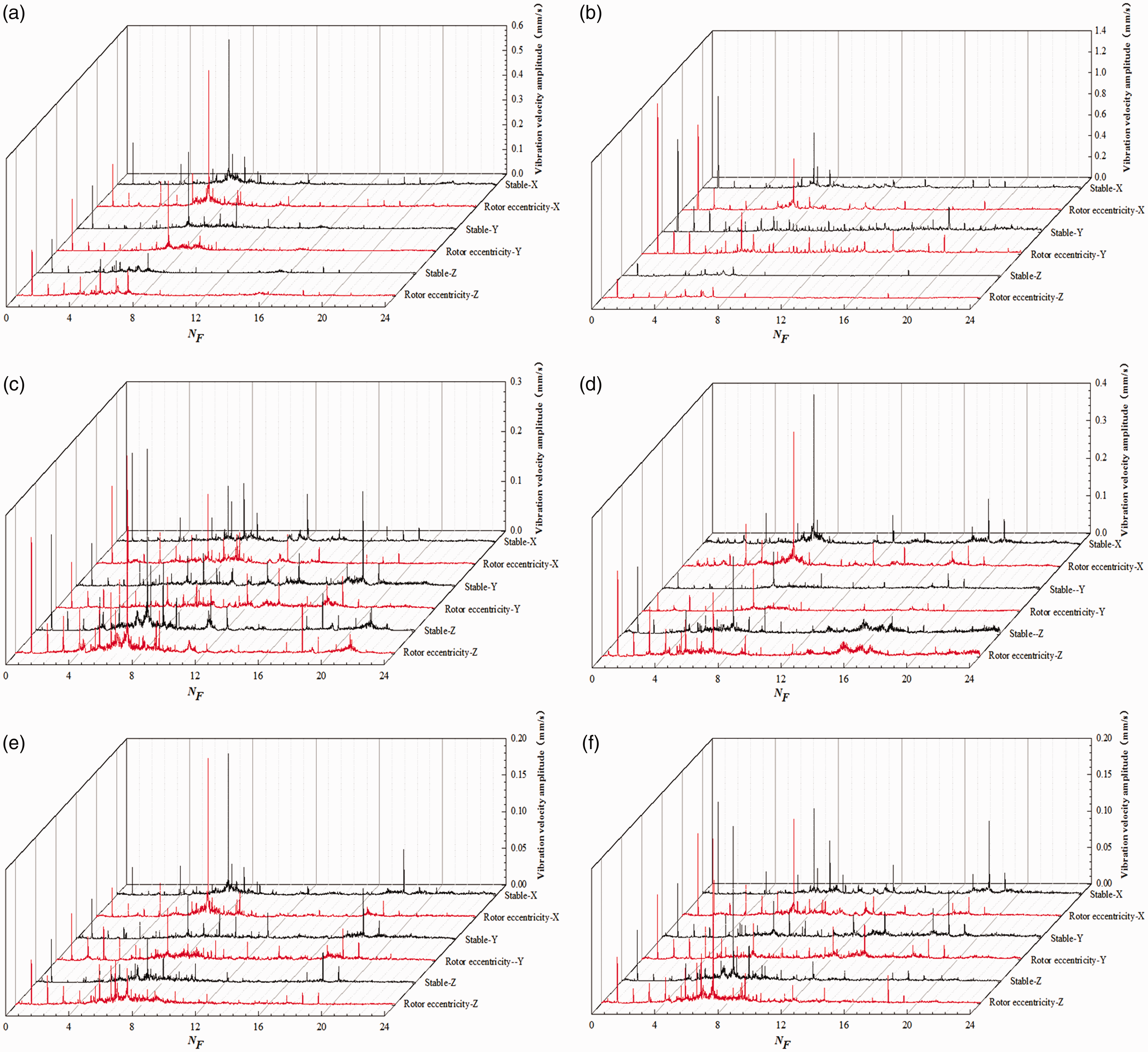
Vibration velocity spectrograms at 0.8Qd. (a) V1. (b) V2. (c) V3. (d) V4. (e) V5. (f) V6.
Vibration characteristics at 1.0Qd
Figure 14 shows the vibration velocity spectrogram of six monitoring points V1 through V6 at 1.0Qd. It can be seen that under rotor eccentricity, each monitoring point’s vibration amplitude in different directions increases by different degrees, among which the amplitudes at APF, 2APF and 3APF are the most obvious, while the amplitudes at 6APF and 7APF are slightly changed. Under stable conditions, the vibration in the axial direction is noticeably smaller than that in the horizontal and vertical directions. The vibration in the axial direction under unstable condition due to the rotor eccentricity is minimal, and the vibration amplitude of some points is even larger than that in the horizontal and vertical directions.
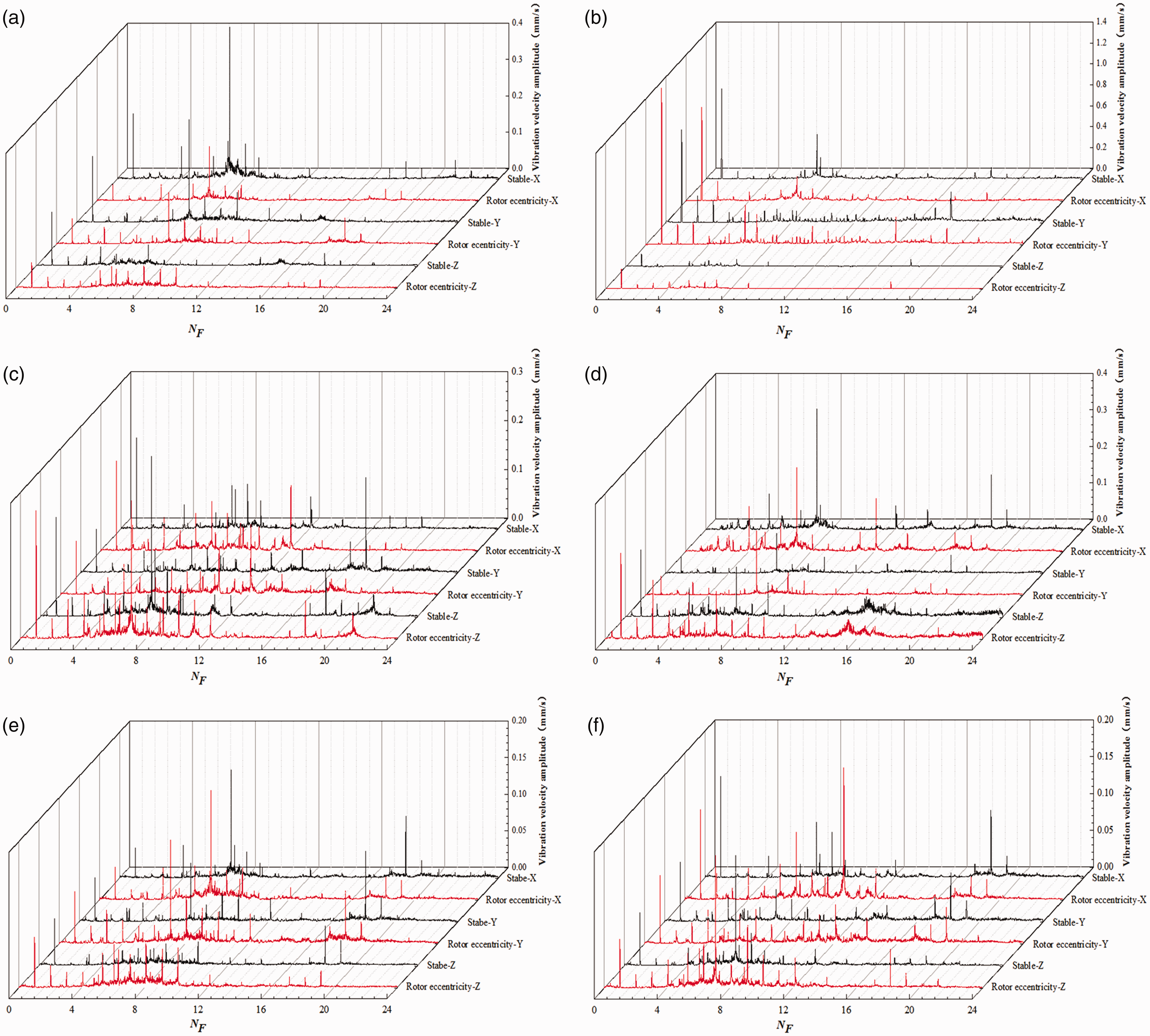
Vibration velocity spectrograms at 1.0Qd. (a) V1. (b) V2. (c) V3. (d) V4. (e) V5. (f) V6.
After rotor eccentricity occurs, the characteristic frequency increases correspondingly, with corresponding peaks from 1APF to 12APF. There are many characteristic frequencies between 4APF and 8APF whose amplitudes are not large. This is because when rotor eccentricity occurs, instability is enhanced, causing the friction between the rotor and stator to increase. Meanwhile, the difference in blade numbers between the first and secondary impellers results in additional characteristic frequencies.
Vibration characteristics at 1.2Qd
Figure 15 shows the vibration velocity spectrogram of six monitoring points V1 through V6 at 1.2Qd. It can be seen from Figure 15 that the characteristic frequencies of monitoring point V2 are smaller than those of the other monitoring points. The main frequencies of monitoring points V2, V3 and V6 are all APF. This is mainly because monitoring point V2 is located at bearing B2, monitoring point V3 is located at the inlet of the five-stage pump, and monitoring point V6 is located at the pump foot near the coupling. Close to the coupling, the APF caused by rotor eccentricity has a bigger influence on these three monitoring points. The main frequencies of the other monitoring points in all three directions are APF and 7APF. The vibration amplitudes of each monitoring point from V1 to V5 increase significantly after rotor eccentricity occurs. The higher frequency vibrations of monitoring points V3, V4 and V5 are larger, and the vibrations are the most obvious at 18APF.
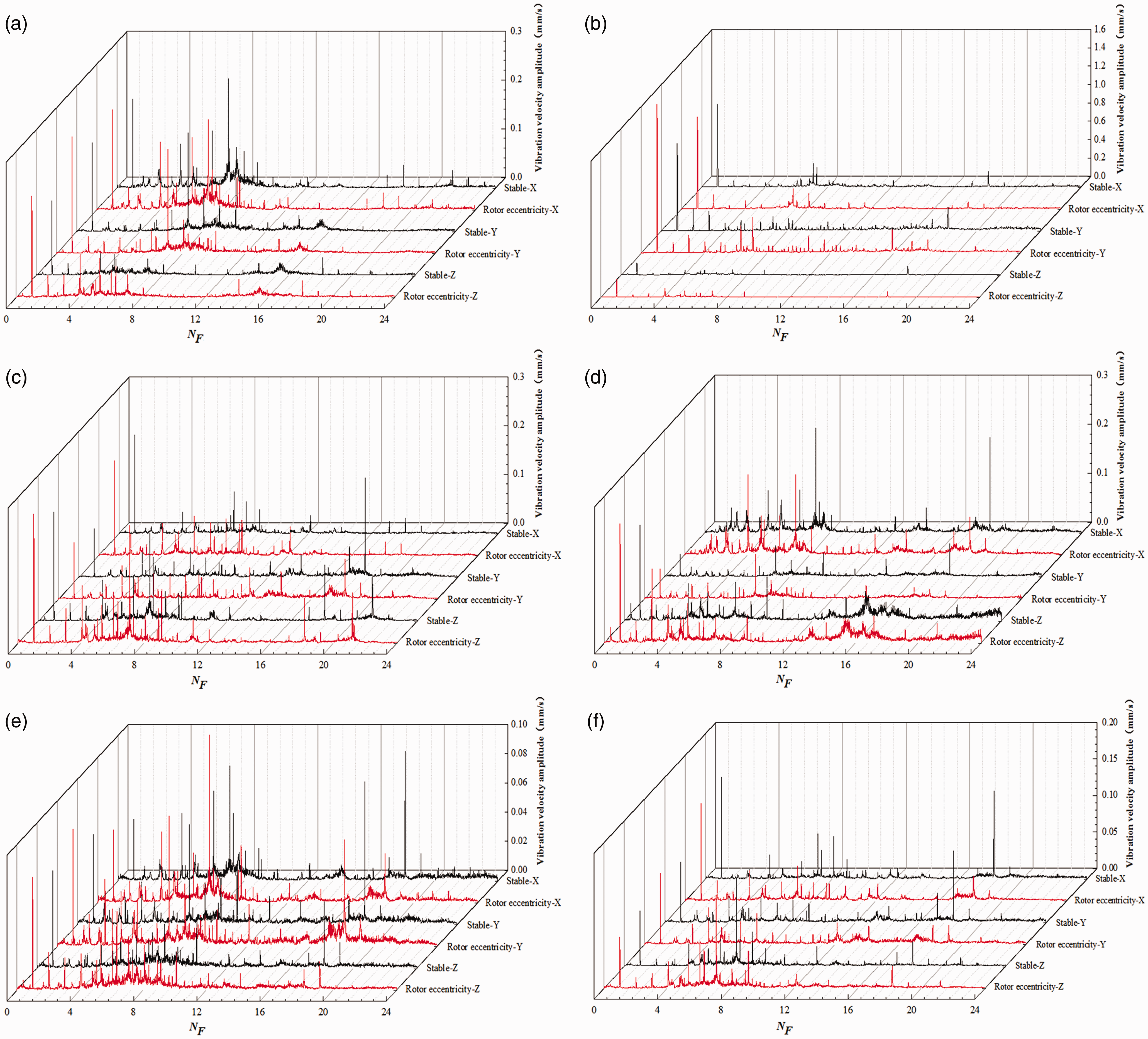
Vibration velocity spectrograms at 1.2Qd. (a) V1. (b) V2. (c) V3. (d) V4. (e) V5. (f) V6.
Vibration intensity
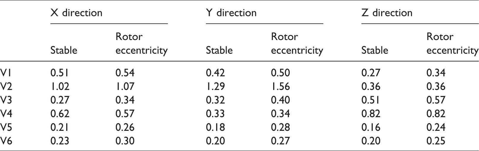
Table 1 shows the vibration intensity of monitoring points at 1.0Qd. It can be observed from Table 1 that after rotor eccentricity occurs, excluding V4, the vibration intensities of other monitoring points in the horizontal direction increase. In the vertical direction, the vibration intensities of all the monitoring points increase. Among them, the increment of point V2 is the highest, at 20.93%, changing from 1.29 mm/s to 1.56 mm/s. In the axial direction, the vibration intensities at monitoring points V2 and V4 do not change, while the vibration intensities of the other four monitoring points increase by different degrees. The vibration intensity of monitoring point V2 is significantly larger than those of the other points, because it is located at bearing B2, which means the tensile force generated by the rotor eccentricity has the greatest influence on it.
Vibration intensity at 1.0Qd (mm/s).
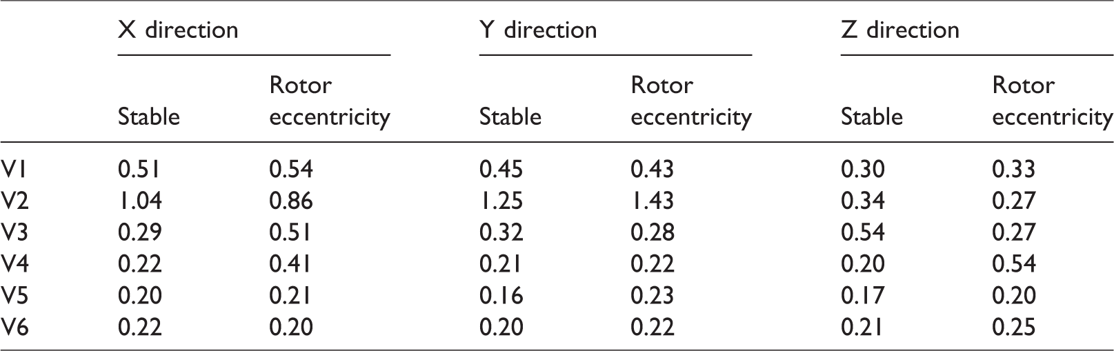
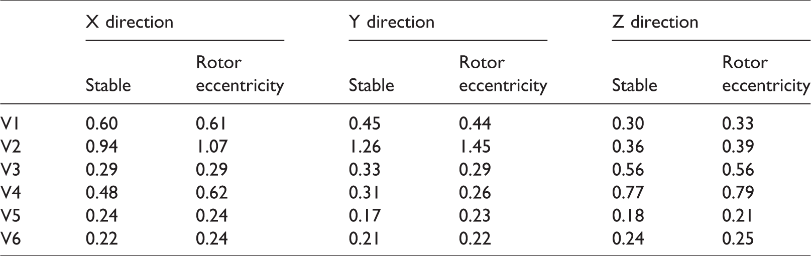
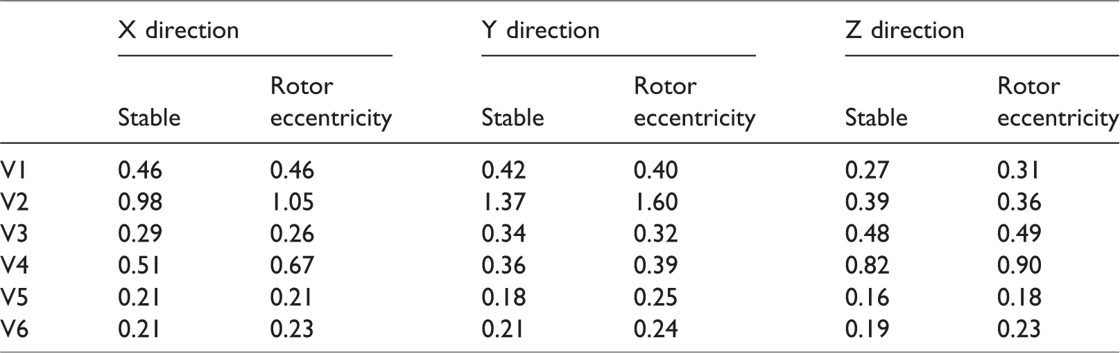
Tables 2 to 4 show the vibration intensities of all monitoring points during 0.6Qd, 0.8Qd and 1.2Qd. Overall, as rotor eccentricity occurs, the vibration intensities in the three cases increase to different degrees. After rotor eccentricity occurs, the vibration intensity increase of monitoring point V2 is larger than that of monitoring point V1. This is because monitoring point V1 is farther from the coupling, and bearing B2 bears the main tensile stress induced by rotor eccentricity, while the influence on monitoring point V1 is small. At 0.6Qd, 0.8Qd and 1.2Qd, the vibration intensities of monitoring point V2 in the vertical direction under unstable conditions due to the rotor eccentricity are larger than those under stable conditions, reaching 1.43 mm/s, 1.45 mm/s and 1.60 mm/s, respectively, which are increases of 14.40%, 15.08% and 16.79%. Compared with rotor eccentricity vibration at the design flow rate, the vibrations of monitoring point V2 under unstable condition due to the rotor eccentricity are the largest in different flow rates. Obviously, when the vibration of the bearing at the coupling increases, rotor eccentricity occurs.
Vibration intensity at 0.6Qd (mm/s).
Vibration intensity at 0.8Qd (mm/s).
Vibration intensity at 1.2Qd (mm/s).
Conclusions
The vibration of the five-stage centrifugal pump with vaned diffusers under stable conditions and unstable conditions due to the rotor eccentricity was measured and analyzed. Some conclusions are as follows. At 0.6Qd, 0.8Qd, 1.0Qd and 1.2Qd, the rotor eccentricity results in an irregular orbit of the rotor axis, which is diffused outward. And the rotor axial orbit contour first increases and then decreases with increasing flow rate. The vibration waveforms in the X and Y directions are periodically distorted sine waves characterized by small fluctuations. As the flow rate increases, the peak amplitude of the rotor axial orbit in the X and Y directions first decreases and then increases. The peak amplitude of the rotor axial orbit at the design flow rate is the smallest. In addition, the main frequencies of the rotor axial orbit vibration in the X direction are 1APF with two peaks, and the main frequency of the rotor axial orbit vibration in the Y direction is 1APF. At the design flow rate, the vibration amplitudes of all the monitoring points in horizontal, vertical and axial directions under rotor eccentricity increase to different degrees. Among these, the increase of axial vibration amplitude is particularly obvious. After rotor eccentricity occurs, the instability increases, and the characteristic frequencies increase correspondingly. There are many characteristic frequencies between 4APF and 8APF. The vibration intensity of monitoring point V2 at bearing B2 is obviously larger than those of other monitoring points. For the off-design flow rates, after the rotor eccentricity occurs, the vibration velocities of monitoring points V2 and V3 significantly increase at 0.8Qd. Monitoring point V3 vibration in the axial direction is larger than those in the horizontal and vertical directions. At 1.2Qd, the vibrations of monitoring points V3, V4 and V5 at high frequencies are larger, and the vibration intensity at the 18APF is more obvious. The vibration intensities in the off-design flow rates are larger than those in the design flow rate, and the increase of vibration intensity of monitoring point V2 at bearing B2 is larger than that of monitoring point V1 at bearing B1.
This manuscript experimentally studies the influence of rotor eccentricity on the vibration characteristics in the five-stage centrifugal pump with vaned diffusers. However, a theoretical analysis of the vibration characteristics of the pump was not considered. Therefore, in subsequent research, a comprehensive study with theoretical analysis, CFD simulation and experimental verification of vibration characteristics in the pump needs to be carried out.
Footnotes
Declaration of conflicting interests
The author(s) declared no potential conflicts of interest with respect to the research, authorship, and/or publication of this article.
Funding
The author(s) disclosed receipt of the following financial support for the research, authorship, and/or publication of this article: This work was supported by National Natural Science Foundation of China (Grant Nos. 51579117 and 51779108), Six Talent Peaks Project in Jiangsu Province of China (Grant No. 2018-GDZB-154) and Priority Academic Program Development of Jiangsu Higher Education Institutions (PAPD).