
Abstract
This article presents the dynamic model of three eccentric rotors driven by induction motors and respectively derives the response equations of the three directions with different frequency in a vibrating system. On account of the difficulty to realize multifrequency self-synchronization, the controlling method is used to realize the synchronization of the speed and phase. In this article, the fuzzy PID method is introduced to control the vibrating system which is based on a master–slave controlling strategy. And a tracking method based on the phase ratio is proposed. The effectiveness and stability are shown in the numerical simulation and the experiment validation is given to certify the accuracy of the theory. In the meanwhile, the arbitrary of the multifrequency is also demonstrated. Finally, some conclusions are summarized to present the significant in the engineering.
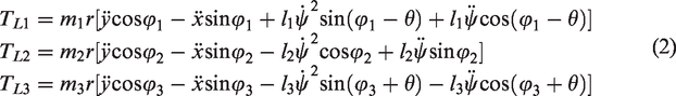
Introduction
Recently, with the development of the industrial technology, people are not satisfied with the traditional industrial equipment and the manufacture requirements. So, some more cheaper and intelligent industrial equipment are bought in. For example, the traditional structure of two shafts needs gears to connect them together to reach the same speed or special speed ratio wanted. This structure increases the cost and weight of the system.1–3 To improve this structure, the concept of synchronization is proposed by Blekhman who illustrates the self-synchronization theory of two eccentric rotors (ERs). 4 Moreover, he also shows the generalized stability theory of self-synchronization and controlled synchronization.5,6 Wen et al. 7 study the theory of self-synchronization in detail. They establish the dynamical model of two motors in a vibrating system and finally show the stability criteria and synchronous conditions. Meanwhile, they present the concept of multifrequency synchronization and realize 2 and 3 times frequency self-synchronization in a vibrating system which exists non-linear springs. Junkichi 8 studies the multifrequency self-synchronization and also acquires the results. In their work, four motors are installed on a rigid body with four springs. The motors are divided into two groups. One group is on the top and the other is on the bottom. Each group is symmetric along the y axis. However, the two groups are not symmetric along the x axis. Due to this unsymmetrical installation, the vibrating system realizes multifrequency self-synchronization. Zhao et al.9–11 establish the electromechanical coupling dynamics model of the induction motors. They use the small parameter method to obtain the eigenvalues of the dynamic equation. And the stability criterion is replaced by the eigenvalues when the vibrating system is at a stable state. Hou and Fang 12 finish the research about the synchronization and stability of two unbalanced rotors. Not only the theory of the self-synchronization get a development but also the experiment. Zhang et al.13–15 do a deep research. Their work shows three kinds of situations which are respectively near resonance, over resonance and far resonance. Most of all, the experiment of self-synchronization is studied, which can effectively certify the accuracy of the theory. Moreover, the self-synchronization can also be realized with a disturbance which is named synchronous transmission. In this work, when the power of one motor is cut off, the two motors can still reach the synchronization state.
Although the self-synchronization can be realized, it always needs some strict conditions. With the development of the intelligent control theory, many kinds of control method are bought in the motor control.16–18 Zhang et al. and Zhao et al.19,20 finish the speed synchronization with the controlling method. Kong et al.21–24 study the base frequency-controlled synchronization and finally realize the speed and phase synchronization. In their work, the adaptive sliding mode control (ASMC) algorithm is applied via a modified master–slave structure to realize the synchronization with a zero phase difference.
The base frequency synchronization can only realize the motion by straight line (the motors rotate with the opposite direction) or cycle (the motors rotate with the same direction). This phenomenon restricts the motion mode of the vibrating screen and has an influence of the production efficiency. However, the multifrequency synchronization has many different kinds of motion modes and can enlarge the amplitude which can improve the effectiveness of the vibrating screen in the engineering. Although the multifrequency self-synchronization can be realized, it can only realize one multifrequency motion in one working condition. When the speed ratio is changed, the vibrating system cannot reach the synchronization state. This kind of model is lack of arbitrariness with the speed ratio and phase ratio and is very inconvenient. So, in this article, the multifrequency-controlled synchronization is studied to solve the problem above. In section ‘Dynamic model of the vibration system’, the mechanical–electromagnetic coupling model of the vibration system is given and the responses of the three directions are shown. In section ‘Design of the controlling system’, a modified master–slave strategy and a method of phase ratio are used into the vibration system and the fuzzy PID method is bought in to control the speed and phase of the motors. In section ‘Results and discussion’, the numerical simulation and experimental verification are given to certify the effectiveness and stability. Finally, in section ‘Conclusions’, some conclusions are listed.
Dynamic model of the vibration system
In this section, the model of the vibrating system is given firstly. And then, the electromechanical coupling dynamics model of the induction motor is shown. Finally, the amplitude responses of three directions are derived.
The model of the mechanical system
In this chapter, the structure of the vibration system is shown in Figure 1. Usually, the theory of elastic deformation should be considered in the engineering. But in this article, the rigid body is connected with four steel plates and the thickness of the plates is about 1 cm. When the vibrating system is in a stable state, the working frequencies are much higher than the natural frequency of the rigid motions of structures and lower than those of elastic vibration of steel plates. Therefore, the elastic deformation and elastic vibration can be neglected. The structure can be simplified as a rigid body.
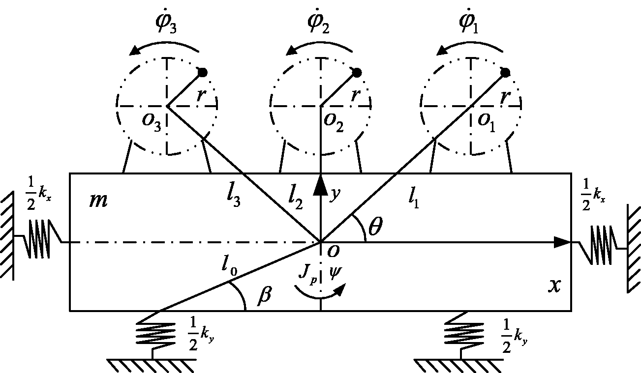
Dynamic model of the vibratory system.
As demonstrated, the model of the mechanical system consists of one rigid body, four springs, a base support and three ERs driven by inductor motors. Three inductor motors which rotate in the counter-clockwise direction are installed on the rigid body. Motor 1 is the master motor and motors 2 and 3 are slave motors. Motor 2 is installed on the center line. Motors 1 and 3 are symmetrically installed based on the center line. The left is motor 3 and the right is motor 1.
The model of the electromagnetic system
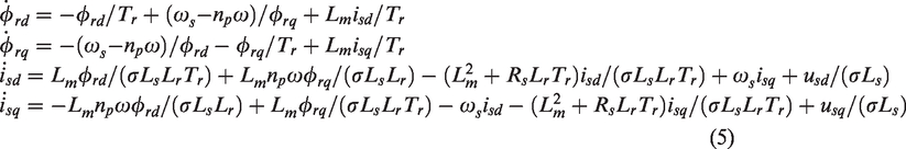
The electromechanical coupling model of the inductor motor is divided into two parts. One is the mechanical system which is shown in section ‘The model of the mechanical system’. The other is the electromagnetic system. According to the electrical machinery theory, the model of the induction motor is given as below.
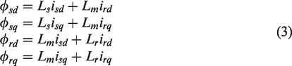
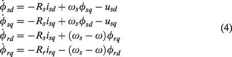
Equations (3) and (4) respectively represent the flux-linkage equations and voltage equations of the induction motor in the synchronous reference frame of the d and q axis. Due to the feature of the squirrel cage motor, its inner structure forms a phenomenon of short out. Hence,

Because of

As shown above, np, Lm,
Responses of the vibrating system
With the theory of non-linear dynamics, the phase difference of motors in the multifrequency synchronization can be expressed as
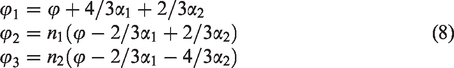
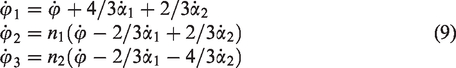
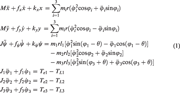
According to equation (1), a conclusion can be obtained that the motion of the vibrating system is periodic when the system is at the synchronous state. So, the change of the mechanical angular velocity of a motor is also periodic. The rotating periods of the motors are respectively T1, T2 and T3. There must be a positive real number T which is the least common multiple period of the motors to satisfy

When the vibrating system is at the synchronous state, equation (10) can also be derived as
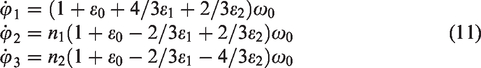
Take equation (11) into equation (1) and make
According to the synchronization theory, the trajectory of the vibrating system is decided by responses in the three directions. From equation (12), it can be concluded that the responses change with the parameters n1 and n2. With different n1 and n2, the trajectory presents various kinds of forms. In the multifrequency synchronization, the parameters n1 and n2 can be suitably adjusted to increase the amplitude which is needed to improve the efficiency in the engineering.
Design of the controlling system
Although the average angular velocity
Design of the electromechanical coupling system
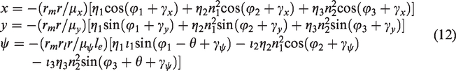
As shown in Figure 2, the controlling law of the master–slave form is adopted. The induction motor 1 is the master motor and the induction motors 2 and 3 are slave motors. The induction motors 2 and 3 trace the induction motor 1 with the phase ratio. The rotor flux oriented control (RFOC) and fuzzy PID method are used on the electromagnetic system of the induction motors.
Flow diagram of the controlled system.
The RFOC in Figure 2 is shown as Figure 3. The given speed
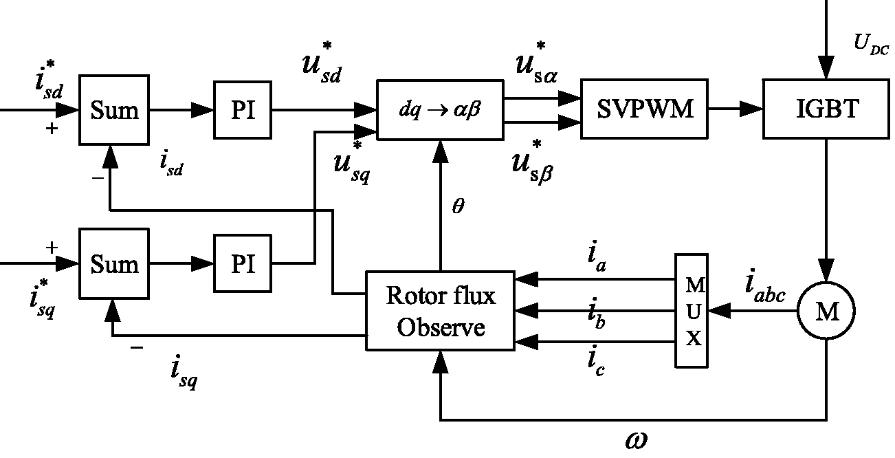
RFOC: rotor flux oriented control.
Design of the fuzzy PID method
The fuzzy system can be structured by the following steps.
Step 1: define a fuzzy set
Step 2: use the fuzzy rules with the number of


Two input variables and three output variables are given in this part. The input variables are respectively the error (e) and error change (ec). The output variables are respectively kp, ki and kd. Each of the five variables is divided into seven situations which are respectively NB, NM, NS, Z, PS, PM and PB. NB and PB are the member function of the model Z (zmf). The others are the member function of the triangle model (trimf). The variables are shown in Figure 4.
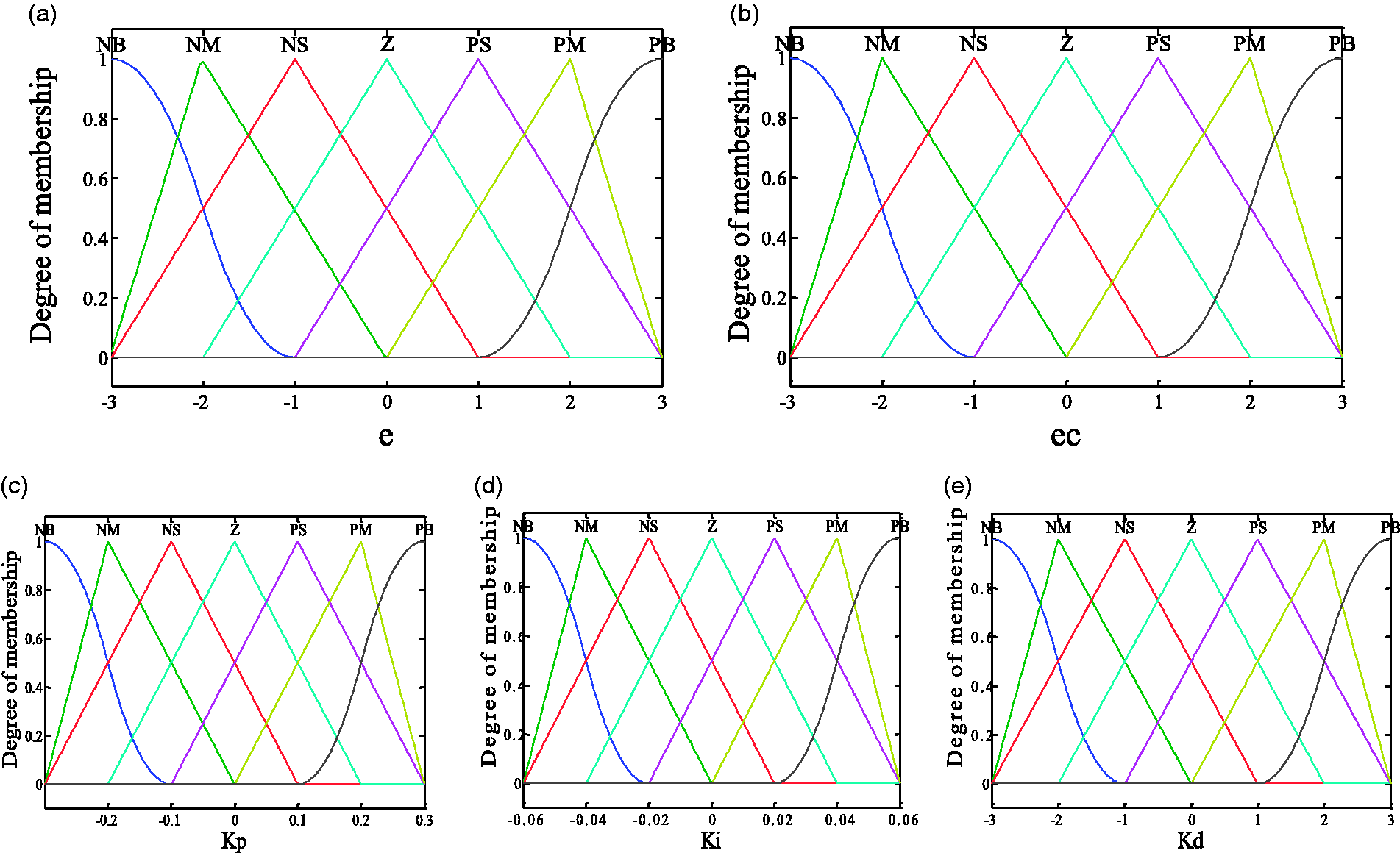
The subjection function of variables. (a) Error (e); (b) error change (ec); (c) parameter kp; (d) parameter ki and (e) parameter kd.
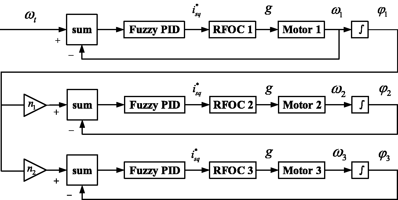
According to equation (13), 49 rules are established with the fuzzy control regulation in this article and then the following equations of the PID parameters can be obtained.
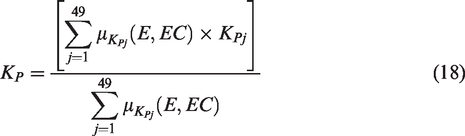
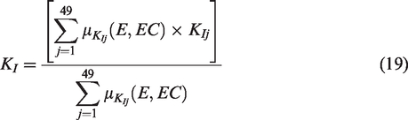

With equations (18) to (20), the surfaces of kp, ki and kd can be obtained in Figure 5.
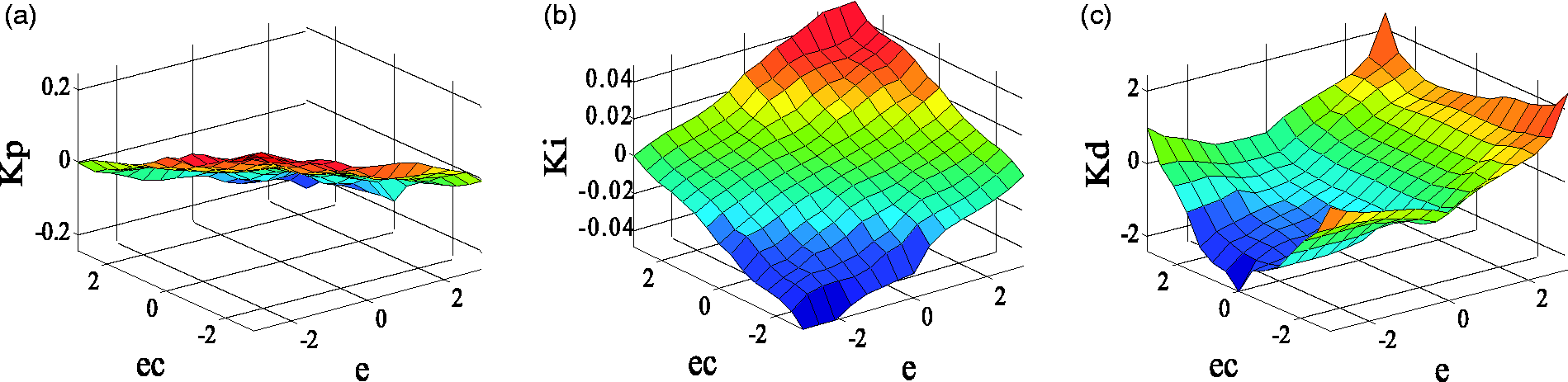
The surfaces of the parameters with kp, ki and kd. (a) Surface of kp, (b) surface of ki, and (c) surface of kd. The horizontal axis x is e and the vertical axis y is ec in all the three diagrams.
The stability analysis of the vibrating system
In this chapter, the rotate speed of the motor 3 and the phase difference between motors 1 and 3 are controlled to reach the target value. With the Lyapunov stability theory, the validations are given.
The stability analysis of the speed
In this part, the speed of motor is chosen as a tracking variable. Then, it can be expressed as


According to equation (20), the control law can be designed as


To guarantee weight coefficient

Take equation (22) into equation (20), the dynamic equation of the fuzzy system can be obtained.

Take equations (23) and (24) into equation (25), the approximation error equation of the system is deduced as

To realize minimum of the tracking error E and parameter error


The stability analysis of the phase
In this chapter, the phase

Similarly, the stability analysis of phase can be certified with the method in section ‘The stability analysis of the speed’.
Results and discussion
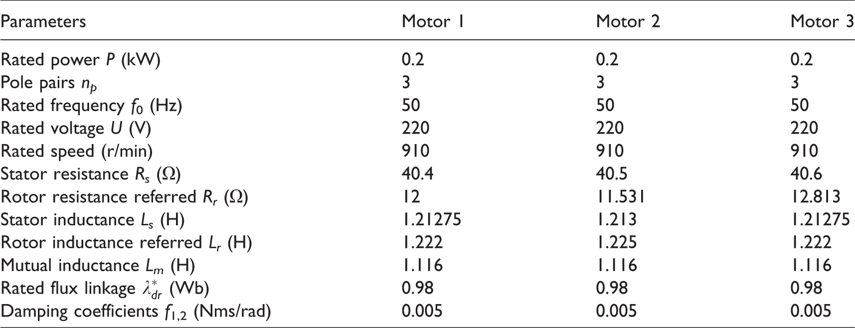
In this part, according to the former theory
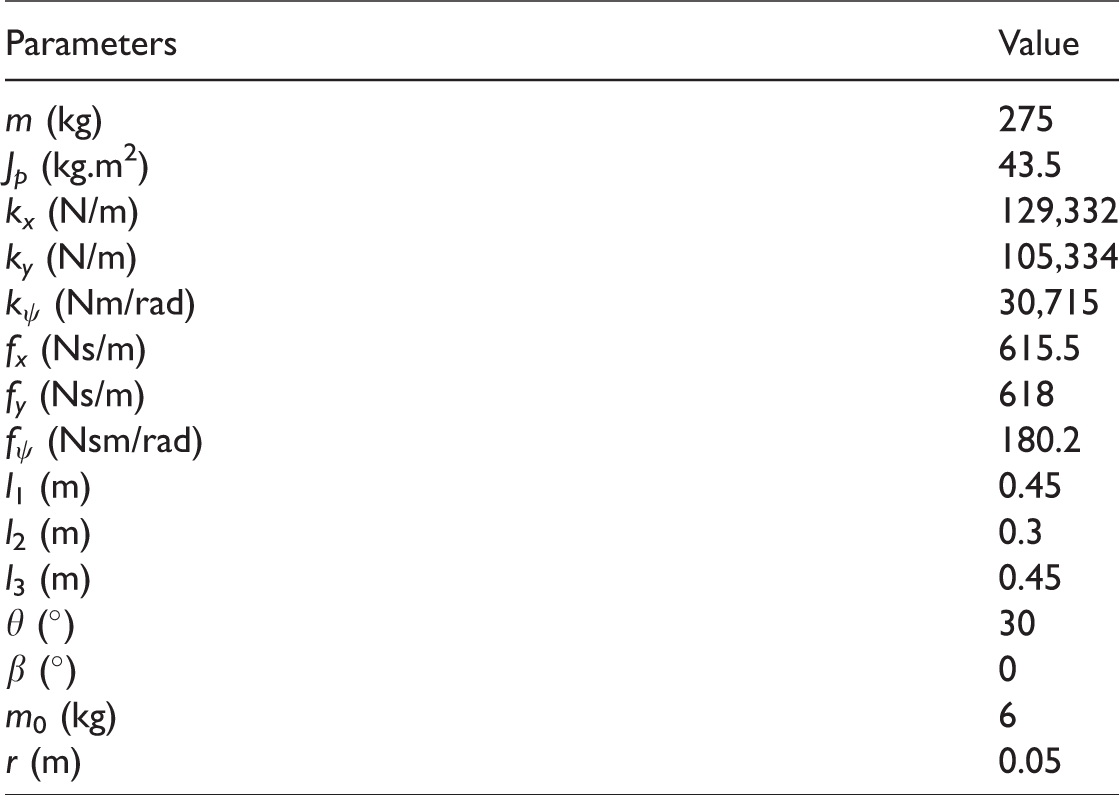
Parameters of the three inductor motors.
Parameters of the vibration system.
Numerical simulation of the multifrequency self-synchronization
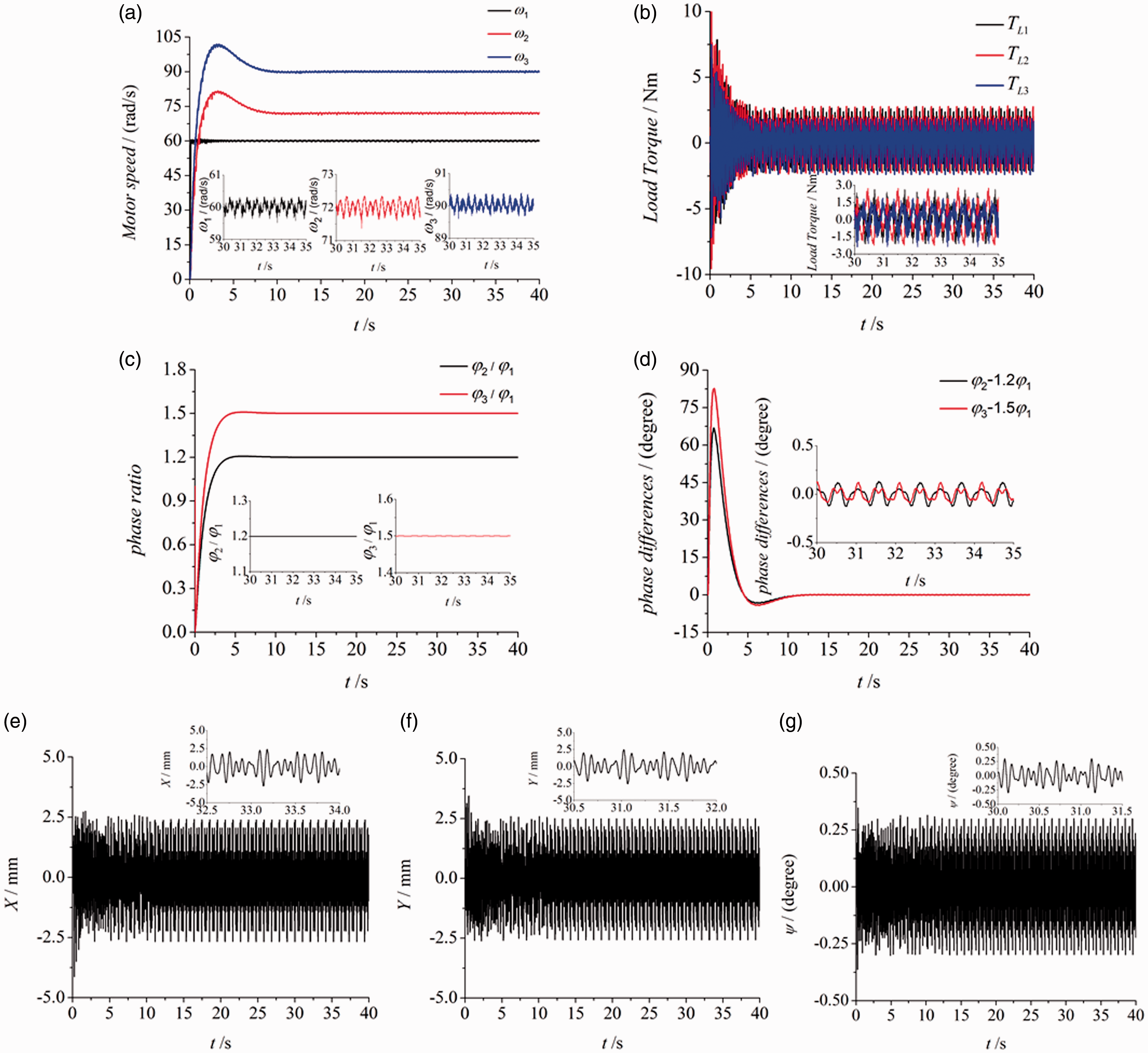
In the theory of self-synchronization, when the speed and phase are both synchronous, the vibrating system is deemed to reach the synchronous state. Otherwise, it does not. As shown in Figure 6(a), the speed of motor 1 is set as 60 rad/s. The speed of motors 2 and 3 are respectively 60 rad/s and 90 rad/s. The initial phase angle
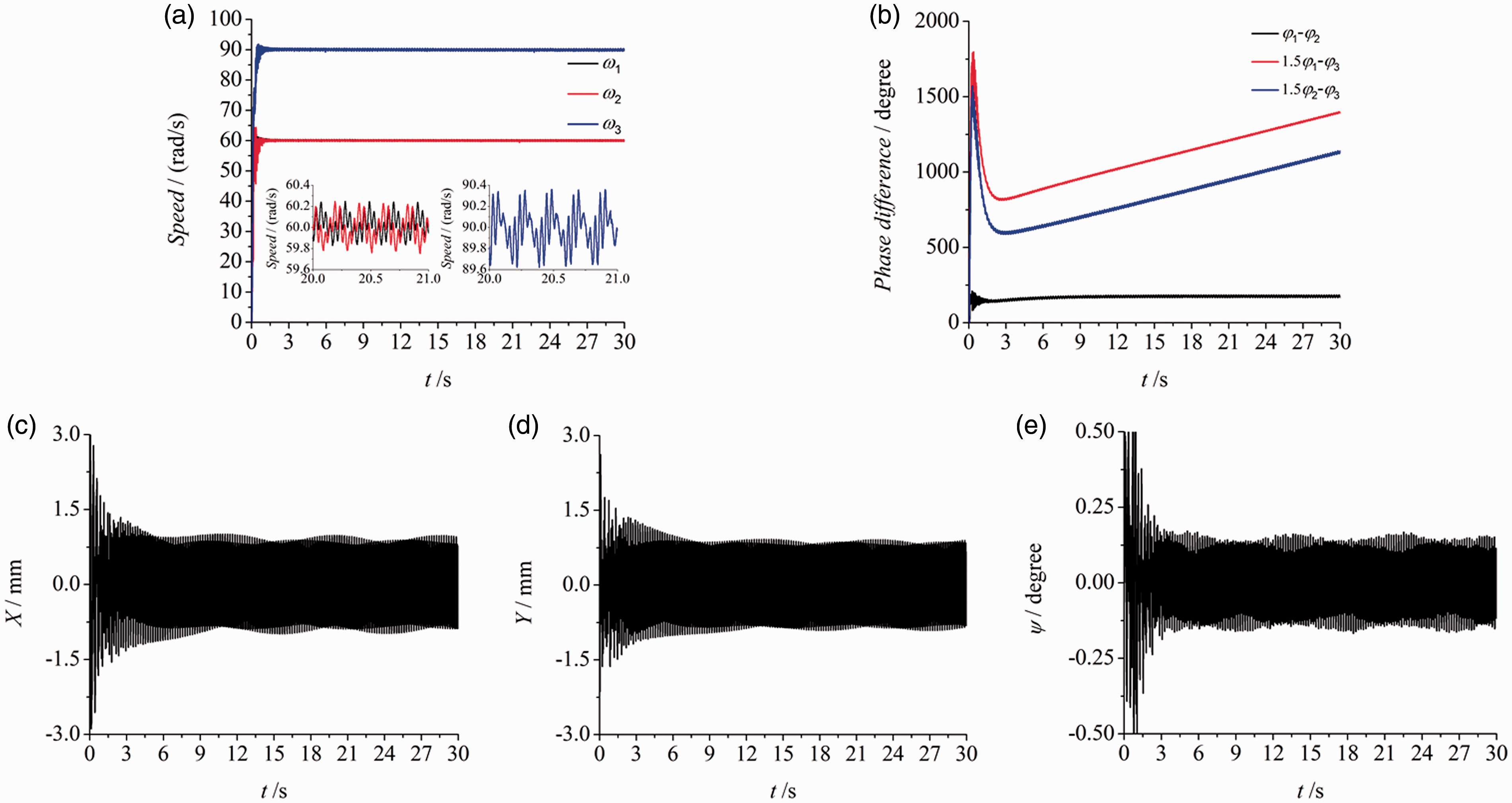
The multifrequency self-synchronization on the situation n1=1 and n2=1.5,
Numerical simulation of the multifrequency-controlled synchronization
According to section ‘Numerical simulation of the multifrequency self-synchronization’, the three ERs cannot reach the synchronous state. To realize the stable multifrequency synchronous state, the fuzzy PID method and the master–slave controlling strategy based on the phase ratio are introduced.
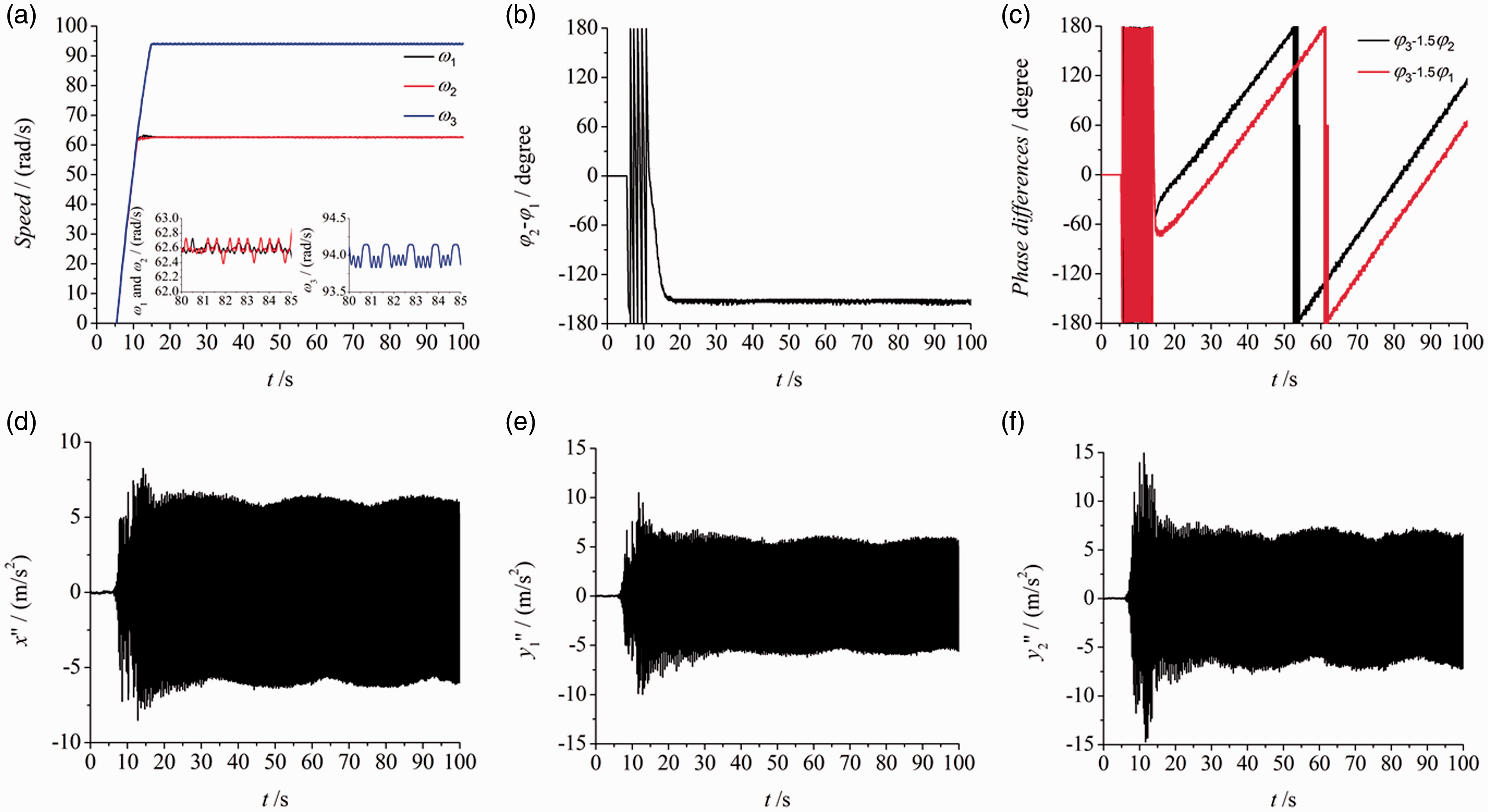
As shown in Figure 7, the same values of the parameters n1 and n2 are used to make a comparison with Figure 6(a) shows the speeds of three motors. The given speed
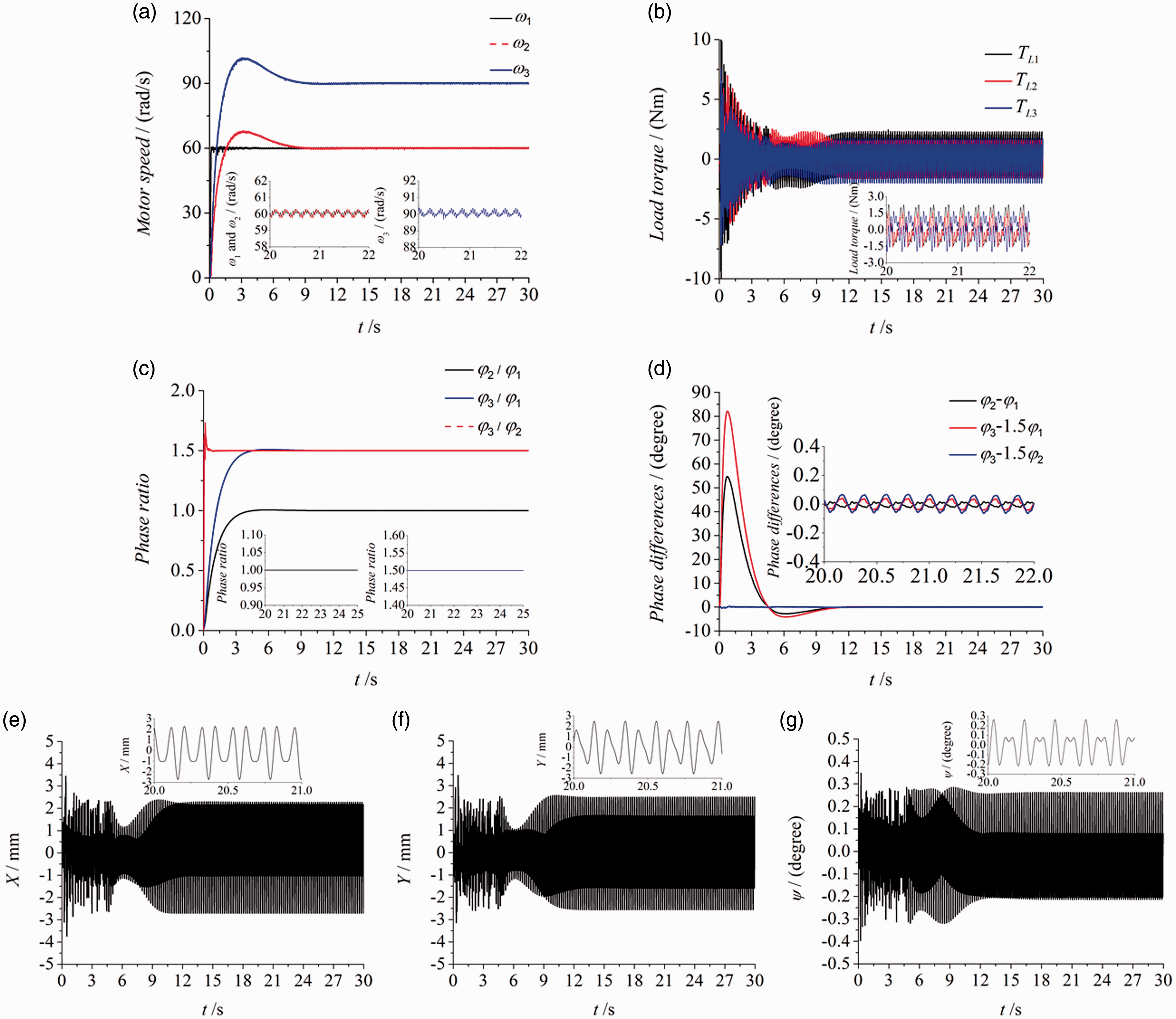
Multifrequency controlled synchronization on the situation n1=1 and n2=1.5,
To certify the arbitrariness of the parameters n1 and n2, they are changed in Figures 8 and 9. And then, the influence on the vibrating system by changing the parameters is discussed.
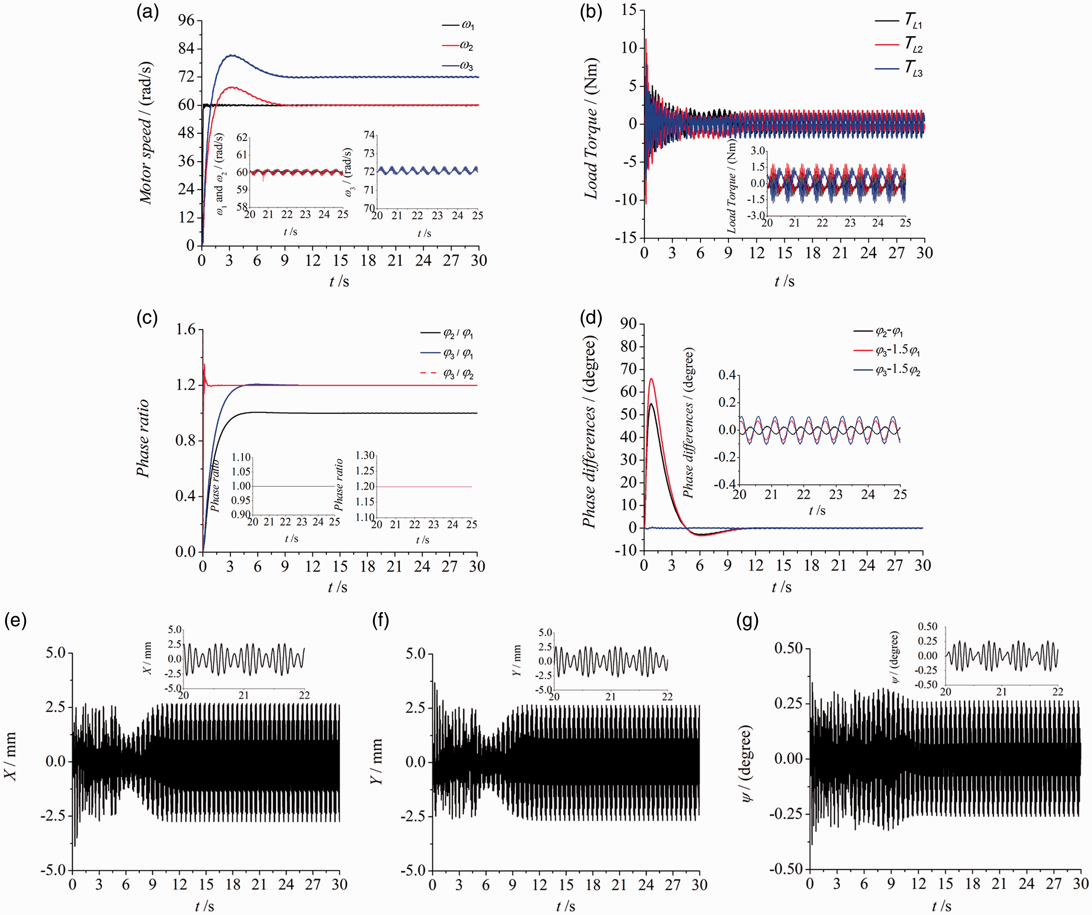
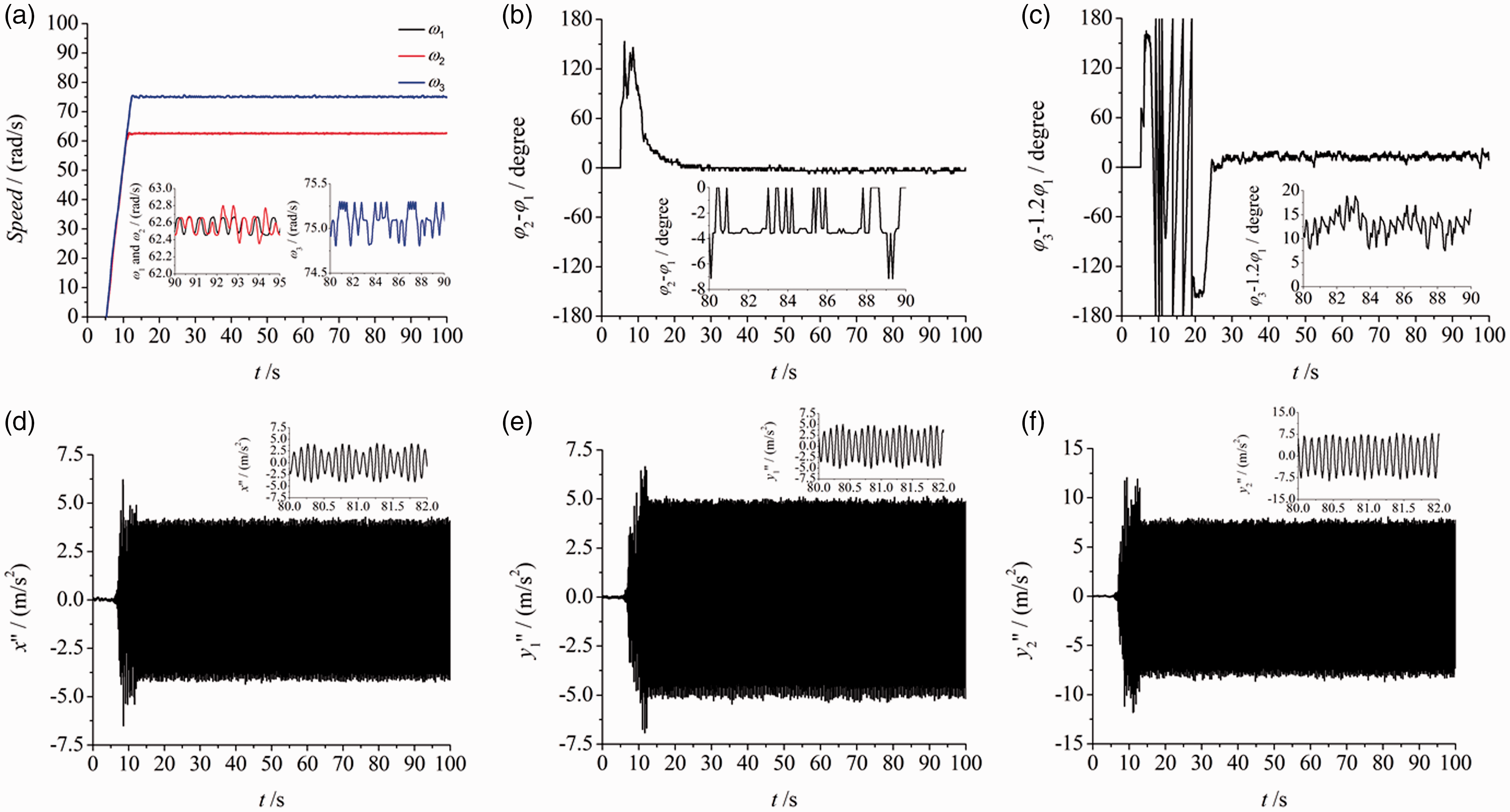
Multifrequency controlled synchronization on the situation n1=1 and n2=1.2,
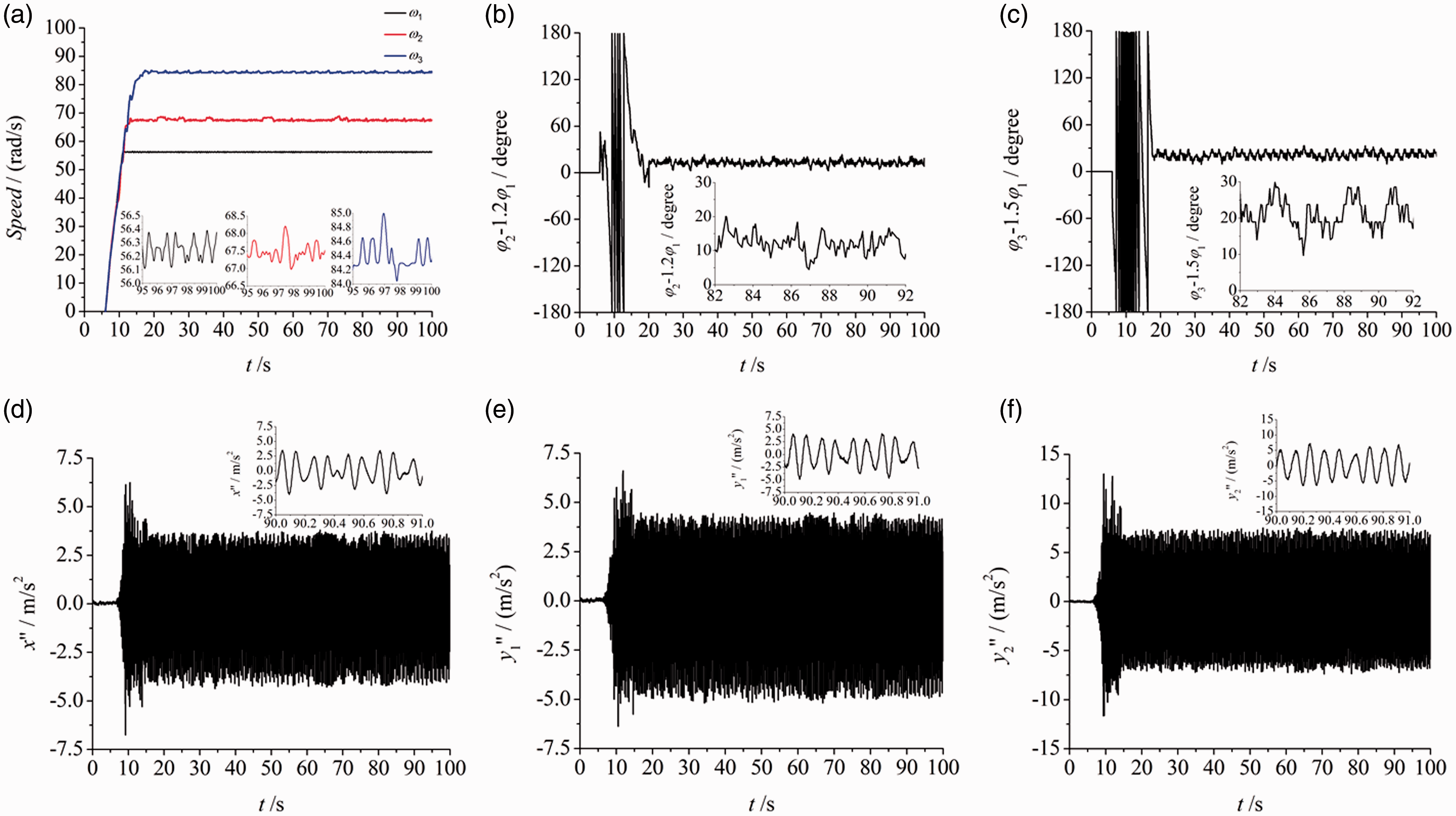
Multifrequency controlled synchronization on the situation n1=1.2 and n2=1.5,
As shown in Figure 8, keep n1=1 and change n2 from 1.5 to 1.2. Similar to Figure 7, the vibrating system still reaches the stable synchronous state which can be obtained from (a) and (c). This conclusion proves that the parameter n2 can be an arbitrary rather than a fixed value only if it satisfies the synchronization and stability conditions of the vibrating system. Comparing (b) in Figure 8 with (b) in Figure 7, the load torque increases with the parameter n2. When n2 equals to 1.5, the values of the load torque are from –2 to 2. When n2 equals to 1.2, the values of the load torque are from –1.5 to 1.5. Comparing (d) in Figure 8 with (d) in Figure 7, there are two phenomena. One is that the curves of the phase difference in Figure 8 are smoother than the curves in Figure 7. The other is that the values of the phase difference in Figure 8 are larger than those in Figure 7. The first phenomenon can be illustrated that the smaller n2 is, the easier the vibrating system can be controlled until n2 equals to 1 which is the base frequency synchronization. The second is summarized that the complexity to realize the controlling of the zero phase difference is decided by the trajectory of the system which is obtained from the responses. The more complex the trajectory of the system is, the more difficult the zero phase difference can be realized.
Different from Figure 8, in Figure 9 keep n2=1.5 and then change n1 from 1 to 1.2. (a) and (c) are shown to prove that the stability of the system has nothing to do with the position of the two slave motors. Changing the position of the motors 2 and 3, the system can still reach the synchronization state. The results in (b) and (d) are consistent with the former conclusion which is obtained in Figure 8. The responses (e), (f) and (g) in Figure 9 appear the characters of three different frequency. Take the x response as an example. When the time is between 33.1 s and 33.3 s, the response presents the character of 1.2 times frequency. When the time is between 33.5 s and 33.7 s, the response presents the character of 1.5 times frequency.
Experimental verification
For combining the theory with the engineering, the experimental verification is given to certify the accuracy of the theory and the effectiveness in the engineering. Figure 10 shows the experiment of multifrequency self-synchronization. In this experiment, the frequencies of three motors which are driven by three inverters are respectively set as 30 Hz, 30 Hz and 45 Hz. There are three acceleration sensors on the frame. One is on the x direction. Another is on the y direction in the center of the frame. The other is on the y direction in the edge of the frame. When the time is about 15 s, the speeds of three motors are stable in (a). (b) The phase difference between motor 1 and motor 2. It is about 160°, which is consistent with the result of the base frequency self-synchronization. However, (c) presents the difference between the base frequency synchronization and the multifrequency synchronization. Obviously, the two groups of phase differences are not constants but monotone increasing curves. The phases are not synchronous. So, this phenomenon proves that the vibrating system cannot reach the synchronous state. And this result is consistent with (b) in Figure 6 of section ‘Numerical simulation of the multifrequency self-synchronization’. (d), (e) and (f) are respectively the responses of x, y1 and y2. Taking the x response as an example, (d) has the same variation tendency with (c) in Figure 6. This conclusion shows the same result between the numerical simulation and the experiment.
The experiment of the multifrequency self-synchronization, where
Figure 11 is the experiment of multifrequency-controlled synchronization. It corresponds to Figure 8 of the numerical simulation. In this experiment, the speeds of three motors are set to 30 Hz, 30 Hz and 36 Hz by three inverters. Motor 1 is the master motor and there is no controlling method on it. Motors 2 and 3 are slave motors which are respectively controlled by two PLCs (programmable logic controller) through the pulses. The measurement and collection of the pulses are accomplished by the Hall sensor. The acceleration sensors on the frame are installed with the same method as the experiment above. (a) The speeds of three motors. When the time is at about 12 s, the speeds of three motors reach the synchronous state. The speed of motor 2 is same as motor 1’s and the speed of motor 3 is 1.2 times than motor 1’s. (b) The phase difference between motor 2 and motor 1. It is about –4°. The experiment always has some error. For example, the installation of the motors (motor 2 may have a few distance from the center line of the vibrating system), the pulse losing (few pulses are missed by the Hall sensor) and so on. So, this result in this article is not considered as
The experiment of the multifrequency controlled synchronization, where
The experiment of the multifrequency controlled synchronization, where
Conclusions
In this article, multifrequency-controlled synchronization of three ERs driven by induction motors in the same direction is investigated. The multifrequency self-synchronization with the dynamic model in Figure 1 cannot be realized. To realize the multifrequency synchronization, the fuzzy PID method based on the phase ratio is introduced and the result is very effective. Not only
Footnotes
Declaration of conflicting interests
The author(s) declared no potential conflicts of interest with respect to the research, authorship, and/or publication of this article.
Funding
The author(s) disclosed receipt of the following financial support for the research, authorship, and/ or publication of this article: This project is supported by the National Nature Science Foundations of China (51675090).