
Abstract
The coupled longitudinal and transverse vibration characteristics of a submarine propeller-shaft-hull system at low frequency are studied in this paper. Two substructures, which are the propeller-shaft subsystem and the submarine hull, are first modelled using the finite element method. The two substructures are then connected through bearings, which are simplified as longitudinal and lateral springs and dampers. The modes, the natural frequencies and the coupled vibration characteristics of the two substructures and their synthesized system are simulated. An experiment studying the dynamic characteristics of a large-scale submarine test-rig is proceeded and compared with the numerical results, showing great consistency. Finally, transfer path analysis of the low frequency excitation forces using power flow method is discussed.
Keywords
Introduction
Low-frequency vibration of a submarine is one key factor restricting its stealth performance. The excitation forces of the rotating propeller-shaft system, such as the residual unbalance of the propeller, the misalignment of the shafts and the fluid-induced forces acting on the propeller, will be amplified in the process of transmission from the propeller to the hull, because of the elasticity of propeller and shafting. These forces are one of the most important sources causing low-frequency vibrations of the submarine. Thus, detailed research on the coupled vibration characteristics of the propeller-shaft-hull system is required to control the sound radiation level of the submarine.
Owning to the complexity of the structure of the propeller and the coupling between the propeller-shaft and the hull, in elementary rotordynamics, the propeller was assumed to be a rigid body using a concentrated mass and its inertia connected to the shaft. However, the elasticity of the propeller has great inference on the force transfer characteristics and noise radiation of the hull. 1 Merz et al. 2 studied the structural and acoustic responses of a submarine hull due to propeller forces. However, he considered the propeller as a modal mass-stiffness system attached to the shaft, and he only implemented the first-order natural frequency of the propeller in the model by neglecting the coupling between the propeller and the shaft. Chen et al. 3 studied the dynamic characteristics of a ship propeller shaft using harmonic blade array elements. The modes and natural frequencies of the propeller were compared to the finite element method (FEM) showing good agreement, but the paper did not discuss the coupling between the propeller-shaft and the hull. A common approach to study the dynamics of propeller is using commercial FEM codes, while it is still difficult and lack accuracy when gyroscopic effect caused by rotation, the fluid-structure interaction (FSI) between the propeller and the entrained water are considered. 4
The vibration characteristics of the shafts are commonly studied using the analytical method, the transfer matrix method or the FEM. Parsons 5 and Schwibinger and Nordmann 6 studied the coupled torsional, longitudinal and transverse vibrations and the mutual influences between them. Pan et al. 7 and Schwanecke 8 employed some simplifications to simulate the water lubricated and the thrust bearings and the coupled vibrations of their supported propeller-shaft system.
At lower frequencies, the submarine hull is able to be simplified as a long, thin stiffened cylindrical shell. The difficulty is how to model the bulkheads, the stiffeners and the distributed concentrated mass. These studies were starting from the infinite cylindrical shell by Rayleigh. 9 Then Forsberg 10 extended that to a finite cylindrical shell with different boundary conditions. Bernblit 11 added different types of spacing stiffeners to the hull and compared the dynamic responses of the hull to the FEM. Wilken and Soedel 12 considered the stiffeners as substructures using the admittance method and analyzed the modal characteristics of the stiffened cylindrical hull. Caresta and Kessissoglou13–16 proposed a series of work to combine the modelling of a cylindrical shell and a conical shell of the submarine hull using an analytical method, a wave approach and a power series solution. Qu and Meng17,18 developed a semi-analytical method for linear vibration analysis of functionally graded bodies of revolution with arbitrary boundary conditions to simulate the submarine hull with either bulkheads, stiffeners or distributed concentrated mass.
Recent years, there have been several studies conducted on coupled low-frequency vibrations between the shafting system and the hull, and the numerical methods and experimental approaches are often implemented instead of analytical research. Dylejko et al. and Dylejko19,20 established a bar model for the shafting system and a cabin hull model to study the admittance results under the action of the thrust bearing. Merz et al.21–23 established a coupled model of the propeller-shaft system and a submarine hull. He found the low-frequency vibrational modes of the hull and the propeller-shaft system may result in a high level of radiated noise. Zhang and Cao24,25 used the FEM to investigate the longitudinal and transverse vibrations of a shaft-hull structure excited by harmonic propeller forces. Zou et al.26,27 developed a three-dimensional sono-elastic method introducing the frequency domain Green's functions to analyze the FSIs, acoustic radiation and acoustic propagation of a ship. The method was validated by calculating the acoustic radiation of a floating elastic spherical shell and an experiment of the underwater acoustic radiation of two ring-stiffened cylindrical shell models. Qi et al.28,29 employed the three-dimensional sono-elasticity method to explore the vibration and acoustic characteristics of a submarine hull with a shaft or without a shaft. The local resonance of the elastic propeller was also taken into account. The correlations of the line spectra of acoustic radiation, the corresponding vibration modes of the hull and the impact on acoustic radiation were analyzed. Li et al. 30 developed a numerical model for a propeller-shaft-hull system using coupled FEM/boundary element method (BEM), and the influence of the shaft vibration on the dynamic responses of the submerged shaft-hull system was analyzed. Su et al. 31 developed a propeller-shaft-hull model to investigate the influences of the non-axisymmetric substructures on the structural behaviors of submerged vessels. The propeller-shaft system was connected to the pressure hull through an irregularly shaped foundation. The numerical solutions were verified by the experimental results, but the propeller was idealized using a plate. There were several applications introducing FRF-based substructuring method (FBSM) in studying the shaft-hull system. Missaoui et al. 32 simulated the coupling between the hull and the shaft by introducing artificial springs via variation equation. Liu and Ewins 33 introduced the elastic boundary to consider the connection between the shaft and the hull. The degrees of freedom of the two substructures were not consistent. Huang et al. 34 developed a dynamic model and an optimization method to minimize the vibration transmission through the marine propulsion shafting system by FBSM. The real propellers as well as the FSI between the propeller, hull and the surrounding water were considered, but the hull structure was simplified. Vibration response characteristics for the coupled system and the power flow transmitted to the foundation were simulated. The results showed that propeller flexibility contributes obvious peaks in the vibration responses and the stiffness of the coupling should be increased to suppress vibration transmission.
In summary, all the aforementioned studies include four ways of implementation. First, study the dynamics of the propeller, the shafts and the hull themselves by ignoring the coupling between the propeller-shaft system and the hull. Second, use theoretical formula with many simplifications to model the coupled shaft-hull system considering the propeller as a rigid body or a lumped mass-spring system. Third, use the FEM to study the coupled vibration characteristics of the propeller-shaft-hull system, while how the elasticity of the propeller influences the vibration responses and how the propeller forces transfer from propeller-shaft to the hull are barely discussed. Fourth, use FBSM to study the coupled vibrations and acoustic radiations of the propeller-shaft-hull system with an idealized propeller or a simplified hull. Last and most important, supportive experimental data are inadequate for all the implementations, which causes difficulty to verify the correctness of the theoretical analysis.
The aim of the present work is to develop a dynamic model to study the coupled low frequency longitudinal and transverse vibrations of a large-scale submarine propeller-shaft-hull system in air using the FEM. The elastic property of a real propeller and the complex connections between the propeller-shaft system and the submarine hull are considered. The dynamic characteristics of the propellers-shaft subsystem, the hull, and the synthesized system are simulated and thoroughly compared with the experimental results. This model can be used as the foundation to analyze the vibrations and acoustic radiations of the propeller-shaft-hull system excited by unsteady propeller bearing force in open water flow or wake flow. The paper is arranged as follows: in the next section, the sketch of the propeller-shaft-hull system and its finite element model are briefly introduced. Then, the modes, the natural frequencies and the coupled longitudinal and transverse vibrations of the propeller-shaft subsystem, the hull and the total system are analyzed. In the subsequent section, an experiment studying the vibration characteristics of a large-scale experimental test-rig is carried out and compared with the numerical simulations. In the penultimate section, a further discussion is focused on the transfer path analysis of the harmonic excitation forces using power flow method. The last section concludes the paper.
Submarine propeller-shaft-hull system
Figure 1 shows the sketch of the submarine propeller-shaft-hull system. The model comprises two substructures: a submarine hull and a propeller-shaft subsystem.
Sketch of the submarine propeller shaft-hull system.
The hull showed in Figure 2(a) is mainly composed of four parts: the cabin shell, the bulkhead, the bearing houses (or seats) and the motor seat; detailed components are listed in Figure 2(b). The cabin shell contains one conical and six cylindrical segments. The diameter of the hull is 1850 mm. The length of the hull, of the conical segment and of each cylindrical segment are 18,580 mm, 5080 mm and 2250 mm, respectively, while the thickness of the conical and cylindrical shell is 5 mm and 6 mm. A stiffening ring is used between any two cylindrical segments to reinforce the structure. The span between two stiffening rings is 2250 mm. In each segment, there are also several stiffeners, where the distances between them are 150 mm.
The submarine hull. (a): Overall structure diagram; (b): detail structure of the conical segment; (c): mesh of the hull; (d): model of the motor and connections between the motor and the motor seat. Note: due to page constraints, (b) and (c) only display part of the hull structure.
The hull is modelled using commercial FEM software ABAQUS as shown in Figure 2(c). The cabin shell is modelled using shell element S4R, and the thickness of the cylindrical and conical segments is 5 mm and 6 mm. The stiffening rings are modelled using shell element S4R with the thickness of 6 mm, while the stiffeners are modelled using beam element B31. The motor seat and the thrust-bearing seat are modelled using S4R with a uniform thickness of 5 mm. Since the stiffness of the thrust-bearing house, the intermediate bearing house and the stern bearing house are far larger than that of the hull, they are modelled using rigid shell elements R3D4 considering the mass and inertia properties added to the centroid of the components. The motor is also modeled using the rigid shell elements R3D4 as shown in Figure 2(d). The total mass of the motor and the drive coupling m0 is attached to the centroid of the motor. The motor is connected to the motor seat with four springs using the stiffness value k2 x , k2 y and k2 z as shown in Table 2. The element types and numbers of the hull are listed in Table 1. The boundary condition of the hull is free.
Element types and numbers of the hull.
The principal physical and property parameters of the propeller-shaft subsystem.
Figure 3(a) shows the overall structure of the propeller-shaft subsystem. It comprises the assembly of a propulsion shaft, a thrust shaft, a propeller and the connecting springs. The total length of the propeller-shaft system L is 4090 mm and the diameter of the solid rotors D is 70 mm. The distances between the propeller, the bearings and the coupling (L1, L2 and L3) are listed in Table 2. The density of the shaft ρs is 7800 kg/m3, the elastic modulus Es is 210 GPa and the Poisson’s ratio υ is 0.3. A five-blade Ni–Al–Bronze Cu3 alloy propeller is studied in the present model, and the diameter of the propeller D0 is 458 mm, the density ρp is 7590 kg/m3, the elastic modulus Ep is 186 GPa and the Poisson’s ratio υ is 0.3.
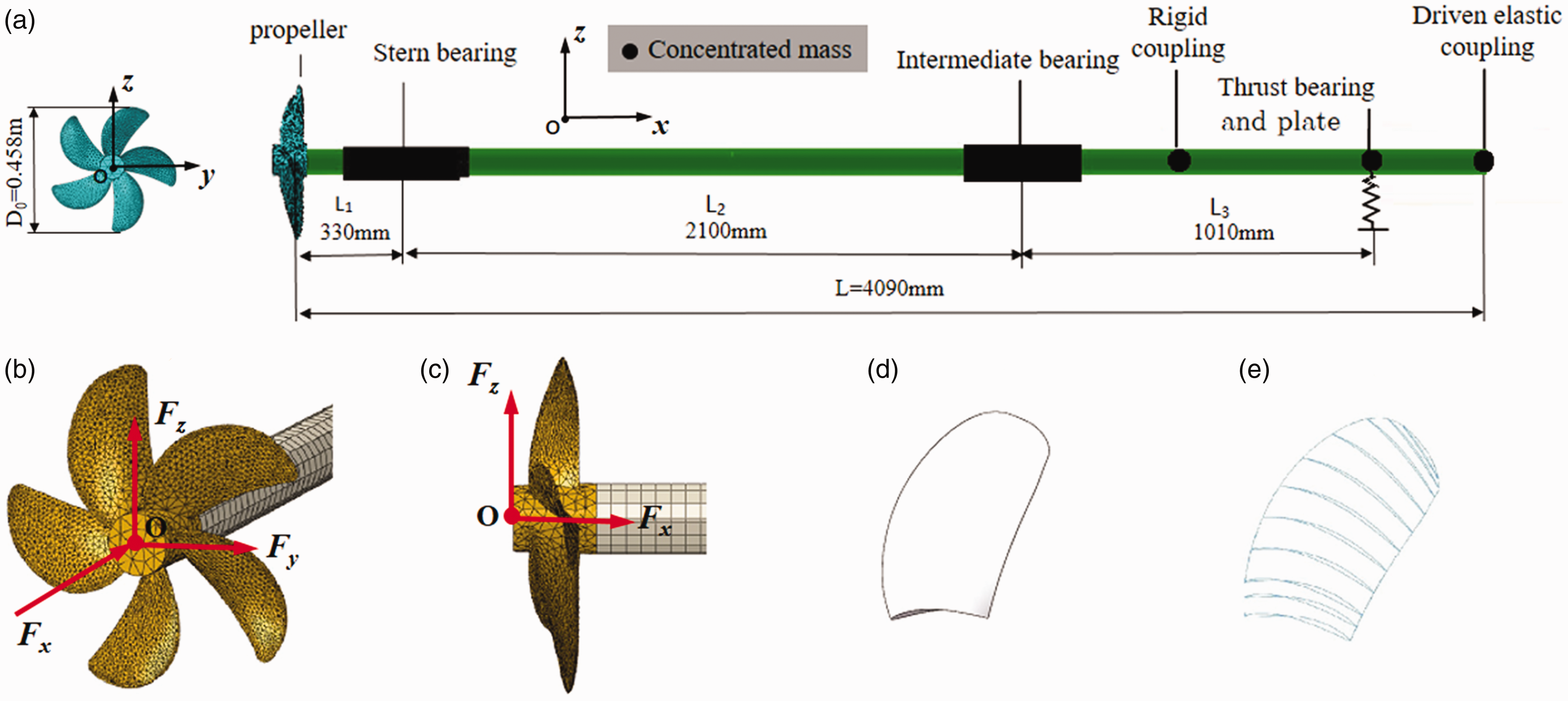
The propeller-shaft subsystem. (a): Overall structure of the system; (b): isometric view of the propeller-shaft subsystem, silver: steel shaft; brown: Ni–Al–Bronze Cu3 alloy propeller; (c): side view; (d): a single blade model; (e): cross sections and splines of a single blade. Note: due to page constraints, only part of the shafting structure is displayed.
A water lubricated stern bearing, a water lubricated intermediate bearing and an oil lubricated thrust bearing are used to support the shafts. A rigid coupling connects the two shafts, which is considered as a concentrated mass m1 and its inertia (J1 x , J1 y , J1 z ) added to the shaft. The thrust-bearing plate is also assumed to be a concentrated mass m2 and its inertia (J2 x , J2 y , J2 z ). A driven elastic coupling connects the thrust shaft to the drive coupling of the motor, which is simplified as a concentrated mass m3 and its inertia (J3 x , J3 y , J3 z ) added to the shaft. As shown in Figure 3(b) and (c), harmonic longitudinal, horizontal and vertical unit forces (Fx, Fy and Fz) are applied to the propeller hub center respectively to simulate the longitudinal and lateral responses of the propeller-shaft subsystem under propeller force excitation. The excitation frequency range is 10–1000 Hz for longitudinal direction and 10–225 Hz for lateral direction.
The finite element model of the propeller-shaft system is modelled using ABAQUS. The propeller is meshed with 17926 10-node quadratic tetrahedron elements (C3D10) and the shaft is meshed with 9276 8-node linear brick elements (C3D8R) as shown in Figure 3(b) and (c). The middle coupling, the thrust plate and the other additional components attached to the shaft are simplified with associated concentrated mass and centralized inertia.
Table 2 lists the principal physical and property parameters of the propeller-shaft system.
Figure 4 shows the synthesized finite element model of the propeller-shaft-hull system. The shafts are connected to the hull via the stern bearing, the intermediate bearing and the thrust bearing. The stern bearing and the intermediate bearing are simplified as horizontal and vertical springs (ksy, ksz for the stern bearing and kiy, kiz for the intermediate bearing) and dampers, while the thrust bearing is simplified as a tri-dimensional spring (ktx, kty and ktz) and damper. A tri-dimensional spring (k1 x , k1 y and k1 z ) and damper is used to connect the drive coupling of the motor and the driven elastic coupling of the shaft. All the lumped mass and stiffness properties are listed in Table 2. The boundary condition of the total system is free. The excitation forces are acting at the same point as the propeller-shaft subsystem. Harmonic longitudinal, horizontal and vertical unit forces (Fx, Fy and Fz) are applied to the propeller hub center respectively to simulate the longitudinal and lateral responses of the propeller-shaft-hull system under propeller force excitation. The excitation frequency range is 10–250 Hz for both longitudinal and lateral directions.
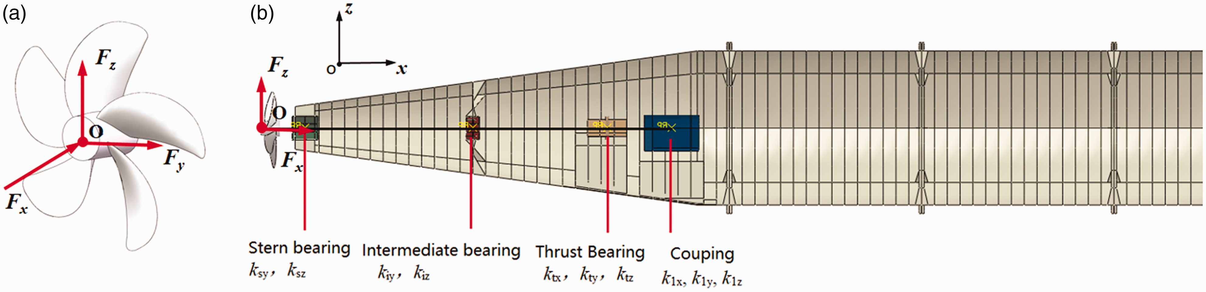
The finite element model of the propeller-shaft-hull system. (a): Excitation force; (b): system model and the connection locations between the propeller-shaft subsystem and the hull. Note: due to page constraints, only part of the propeller-shaft-hull structure is displayed.
Figure 5 is a photograph of the large-scale submarine experimental test-rig. The boundary condition of the experimental test-rig is different from the numerical model. Twelve air springs are installed between the submarine hull and the foundation. The first natural frequency of the test-rig is 2.5 Hz. Since this frequency is much lower than the natural frequencies of the propeller-shaft-hull system, its influence to the dynamic characteristics of the system itself can be neglected.
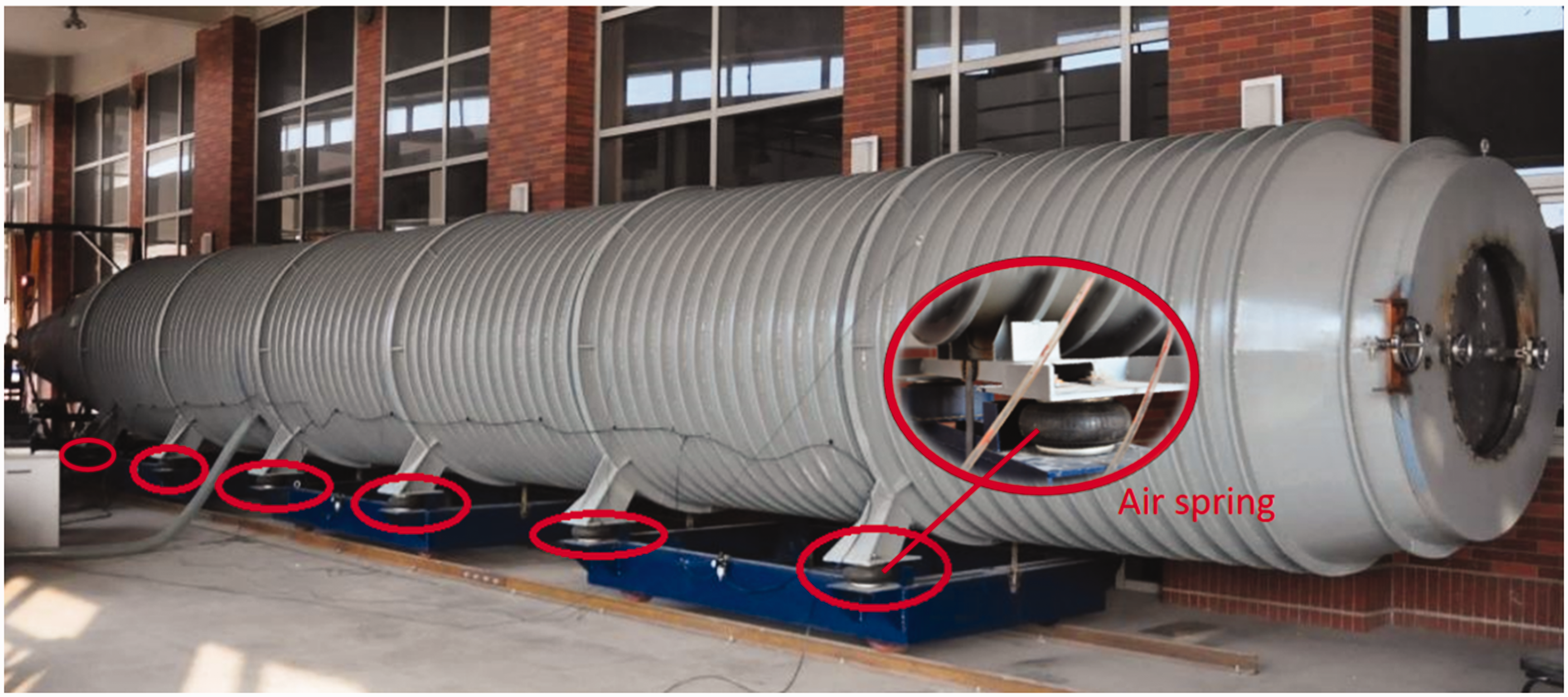
The submarine propeller-shaft-hull experimental test-rig.
It needs to be clear that since the experiment test-rig is surrounded by air, to ensure the model consistency, the numerical simulations are implemented only considering the case that the propeller-shaft-hull system is in air and the longitudinal or lateral unit forces are applied to the propeller hub center.
Coupled vibration characteristics of the propeller-shaft-hull system
In this section, the modes, the natural frequencies and the coupled longitudinal and transverse vibrations of the propeller-shaft subsystem, the hull and the total system are simulated.
Dynamic characteristics of the propeller-shaft subsystem
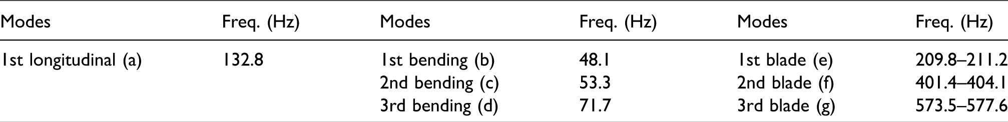
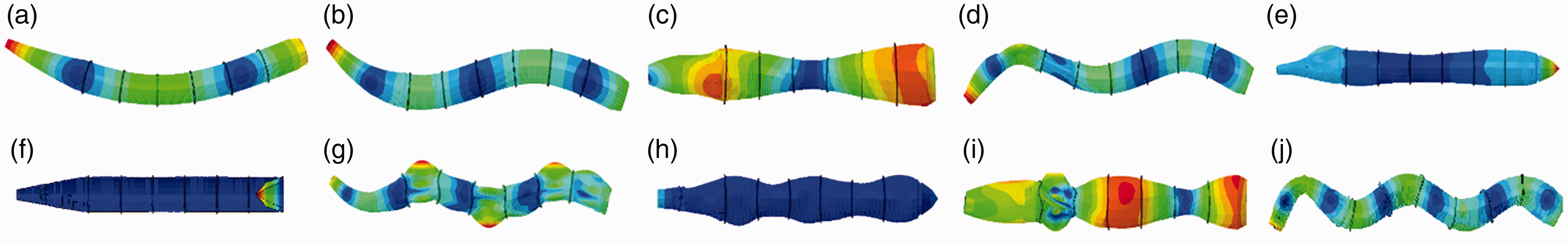
Figure 6 lists the modes of the propeller-shaft subsystem in air using the FEM model. Figure 6(a) to (d) are the first longitudinal and the first three bending modes of the shaft, while Figure 6(e) to (g) are the first three local modes of the propeller at rest. It needs to be clear that the modes of propeller are in groups. In each group, five modes occur almost at the same frequency, which is attributed to the geometric periodicity of the propeller blades. The first group around f ≈ 210 Hz is the single-node bending mode of a cantilever blade, the second group around f ≈ 402 Hz is the two-node bending mode, while the third group around f ≈ 575 Hz is the coupled bending and torsional modes of propeller blades. Table 3 lists the natural frequencies of the above modes using the FEM model. If the propeller is submerged in water, the natural frequencies of each group are obviously lower than those in air. This is because the increased modal mass due to the added mass of the heavy fluid will greatly reduce the lower modal frequencies of the propeller.
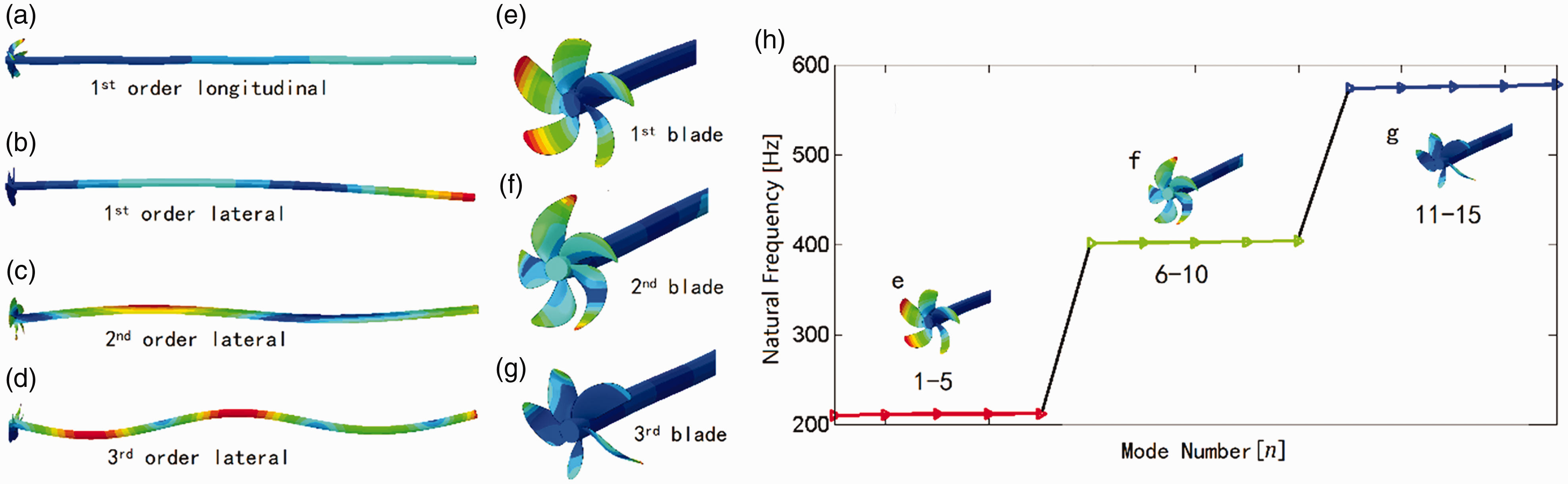
The first longitudinal, the first three bending modes of the propeller-shaft subsystem and the first three local modes of the propeller at rest (ω = 0). Left column (a)–(d): modes of the shaft; middle column (e)–(g): first three local modes of the propeller; right column (h): mode numbers and natural frequencies of the propeller.
The natural frequencies of the propeller-shaft subsystem: The first three bending, first longitudinal and first three local modes of the system at rest (ω = 0).
The motion of a rotating propeller-shaft system is combined by the rotation and the whirling of the flexible rotor. When the whirling motion of the shaft is as the same direction as the rotating motion, it is called the forward whirl and the corresponding critical speeds are called the forward natural frequencies. Similarly, backward whirl is when the whirling motion of the shaft is in the opposite direction of the rotating motion; meanwhile, the corresponding critical speeds are called the backward natural frequencies. If the centrifugal stiffening and gyroscopic effect due to rotation are considered, the forward natural frequencies of the propeller will increase, while the backward natural frequencies will decrease. Figure 7 compares the first natural frequency of the propeller blades at different rotating speeds. However, for a ship propeller, generally the rotating speed is always working within the frequency range around 1–3 Hz (60–200 r/min), which makes the centrifugal stiffening and gyroscopic effect irrelevant to the rotating natural frequencies of the propeller. Therefore, the rotation effect of the propeller-shaft system is not considered in this paper.
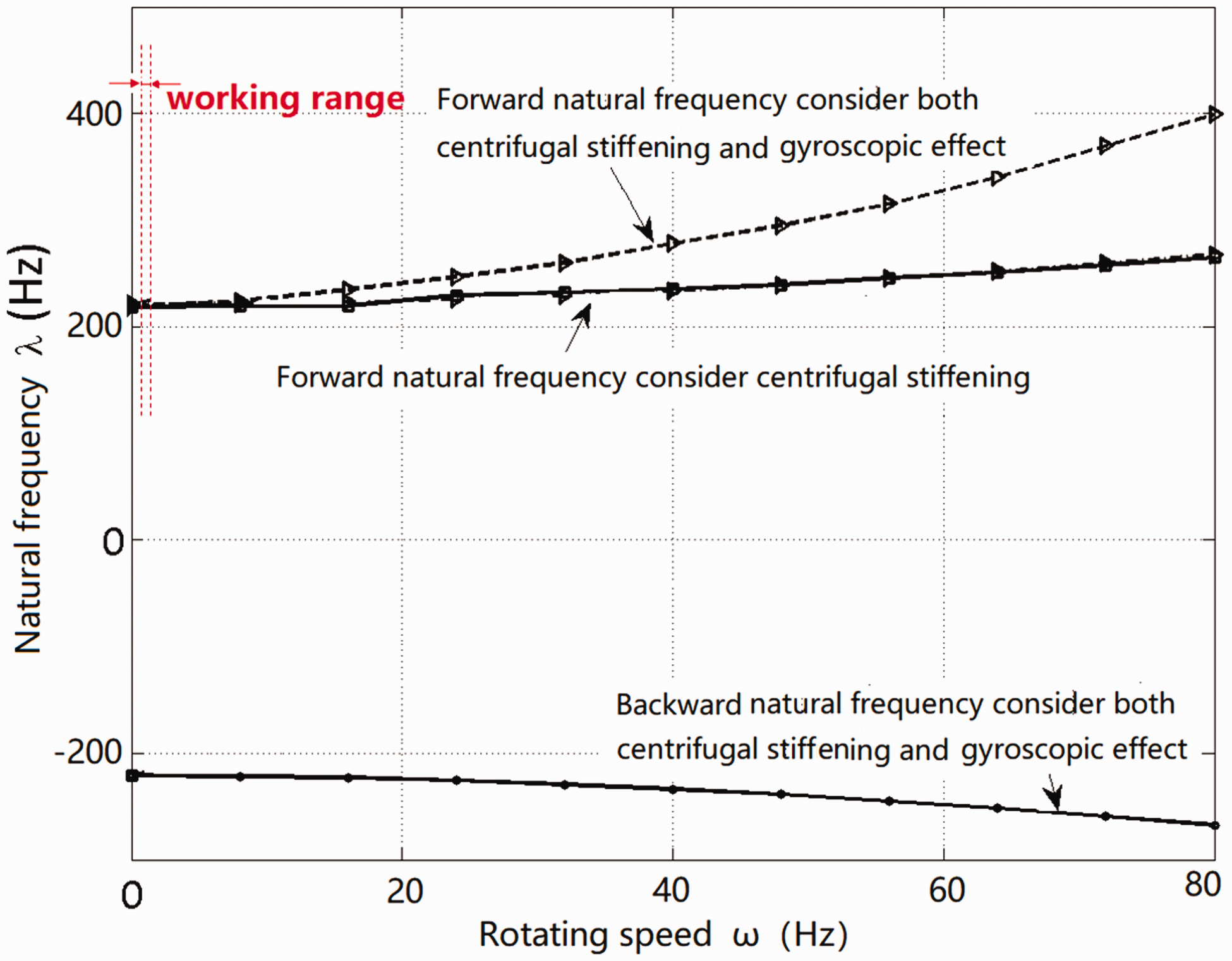
First forward and backward natural frequency of the propeller blades at different rotating speeds using the FEM model considering the centrifugal stiffening and gyroscopic effect.
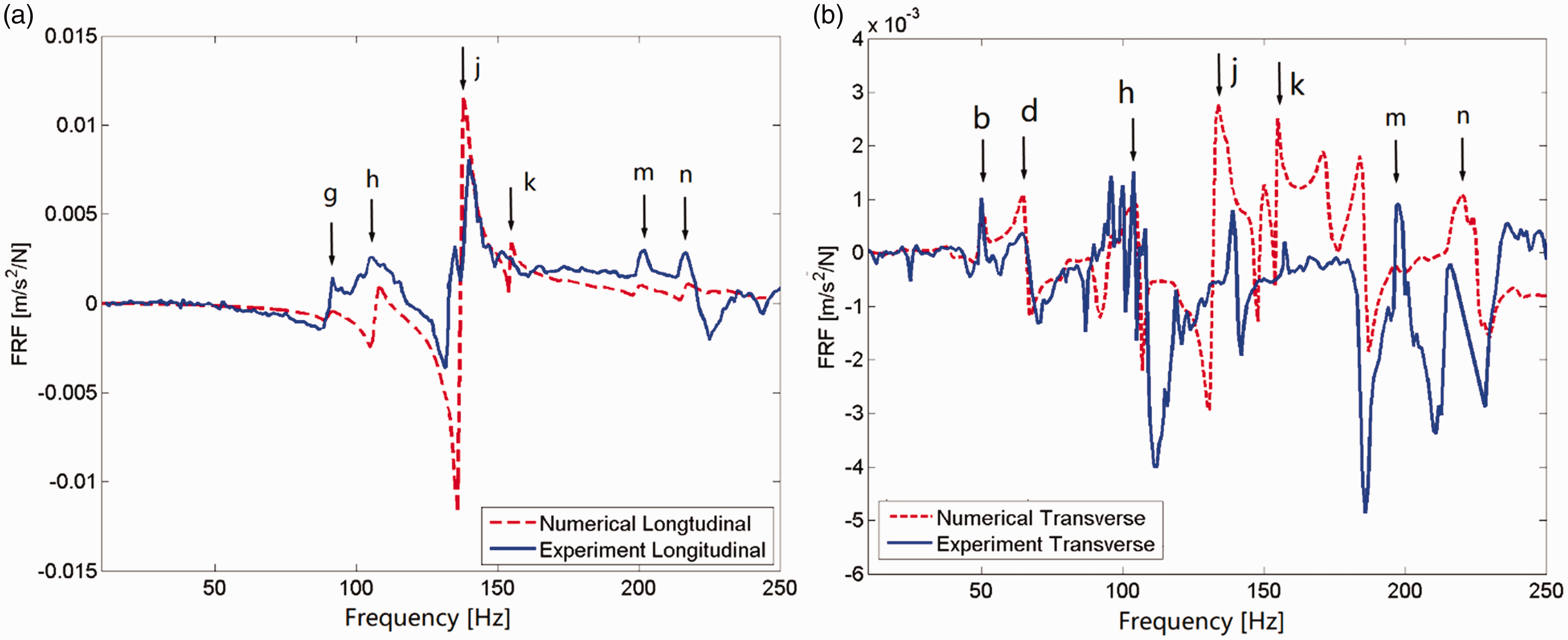
Figure 8 plots the frequency response functions (FRFs) of the propeller-shaft subsystem. The excitation forces are applied to the propeller hub center in either longitudinal or lateral directions. The left column figures in Figure 8 are the longitudinal responses at the stern bearing, the intermediate bearing and the thrust bearing for a studying frequency range of 10–1000 Hz. The frequencies at which peaks in the response amplitude occur (hereafter called the peak response frequencies) are marked with red dashed lines and tagged as a, e, f, g. Figure 8(d) to (f) shows the transverse responses at the stern bearing, the intermediate bearing and the thrust bearing for a studying frequency range of 10–225 Hz. The peak response frequencies are marked with red dashed lines and tagged as b, c, d.
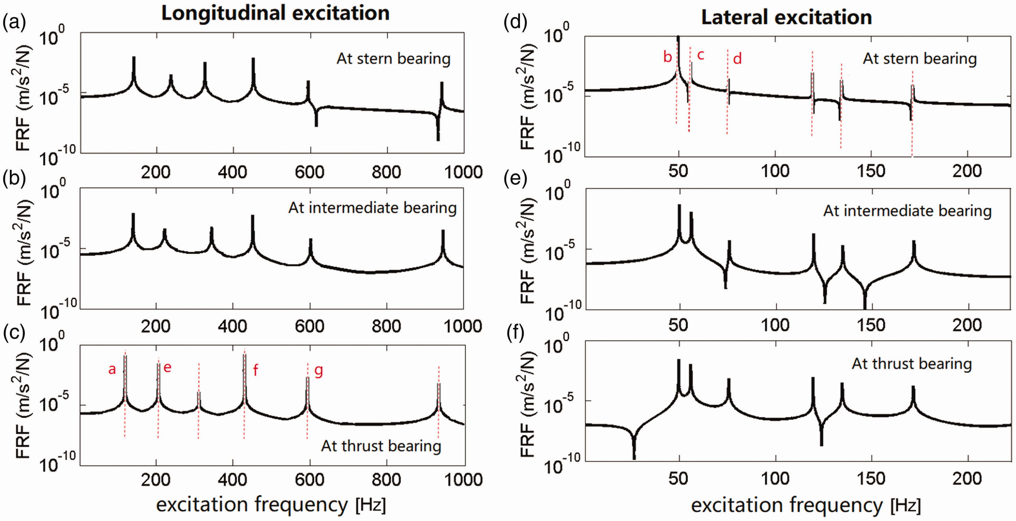
Frequency response functions of the propeller-shaft subsystem under longitudinal and lateral excitation applied to the propeller hub center. Left column: longitudinal responses at stern bearing, intermediate bearing and thrust-bearing node; right column: transverse responses at stern bearing, intermediate bearing and thrust-bearing node. Red dashed lines in Figure (c): the peak response frequencies at thrust-bearing node; a, e, f, g: peak response tagging. Red dashed lines in Figure (d): the peak response frequencies at stern bearing; b, c, d: peak response tagging.
Comparing to the natural frequencies listed in Table 3, we can notice: (1) the peak response frequencies all match the natural frequencies of the propeller-shaft subsystem. E.g. peak a corresponds to the first longitudinal mode of shaft, peaks b, c, d are the first three bending modes of the shaft, and peaks e, f, g are the first three local modes of the propeller blades. (2) The blade local transverse modes are not excited. This is because the blade modes examined here are all in the out-of-plane direction, which are perpendicular to the lateral direction. (3) The longitudinal response at the thrust-bearing node is larger than that at the other two bearing nodes. Similarly, the transverse response at the stern bearing node is much larger than at the other two bearing nodes. Hence, the thrust bearing is the main longitudinal load transfer path from the propeller to the hull, while the stern bearing is the main lateral load transfer path.
Dynamic characteristics of the submarine hull
The natural frequencies and their corresponding modes of the submarine hull in air are simulated following the finite element model illustrated in ‘Submarine propeller-shaft-hull system’ section. Figure 9 shows the global modes of the submarine hull in frequency range of 10–200 Hz. The rigid body motions of the hull are omitted. Table 4 lists the natural frequencies and their characterized vibration modes. If the hull is submerged in water, the natural frequencies will be reduced due to the added mass of the heavy fluid.
Nine global modes of the submarine hull in frequency range of 10–200 Hz. (a): 1st bending mode at 24.8 Hz; (b): 2nd bending mode at 56.4 Hz; (c): 1st torsional mode at 78.2 Hz; (d): 3rd bending mode at 95.4 Hz; (e): 1st longitudinal mode at 105.1 Hz; (f): 2nd bending mode at 134.4 Hz; (g): 4th bending mode at 140.2 Hz; (h): 3rd longitudinal mode at 153.4 Hz; (i): 2nd torsional mode at 156.9 Hz; (j): 5th bending mode at 185.8 Hz.
The natural frequencies and the global modes of the hull in frequency range of 10–200 Hz.
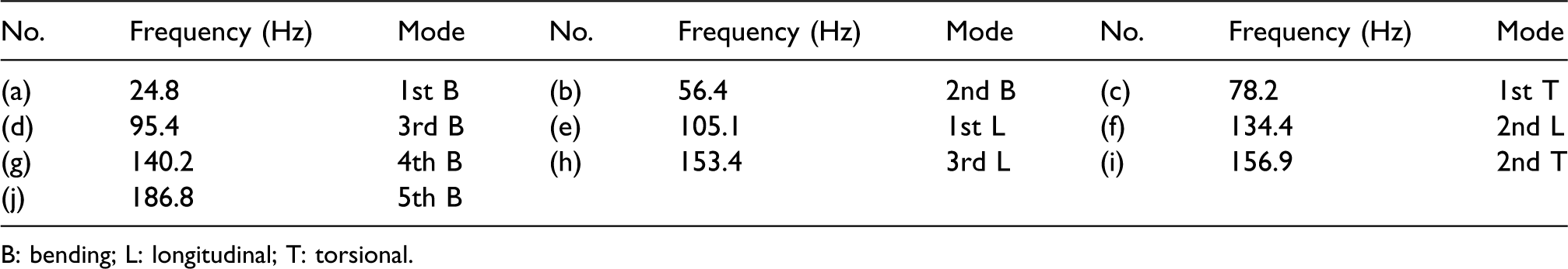
B: bending; L: longitudinal; T: torsional.
We can notice that the global modes are expressed as the bending, torsional and longitudinal vibrations of the hull. It also needs to be clarified that some of the global modes are the combination of the above three types of vibrations, such as mode (e) in Figure 9, which combines the longitudinal vibration of the hull and the bending vibration of the conical segment. This is because the hull is a stiffened asymmetrical thin shell due to the additional structures (such as the motor seat and the thrust-bearing seat). In general, the longitudinal vibration of the hull dominates mode (e), so here we call this mode the first longitudinal mode of the hull.
Similar to ‘Dynamic characteristics of the propeller-shaft subsystem’ section, the FRFs of the hull are simulated. As shown in Figure 10, a harmonic longitudinal unit force excitation (Fx) is applied to a reference point of the thrust-bearing center, and a harmonic lateral unit force excitation (Fy) is applied to a reference point of the stern bearing center. The excitation frequency range is 10–200 Hz.
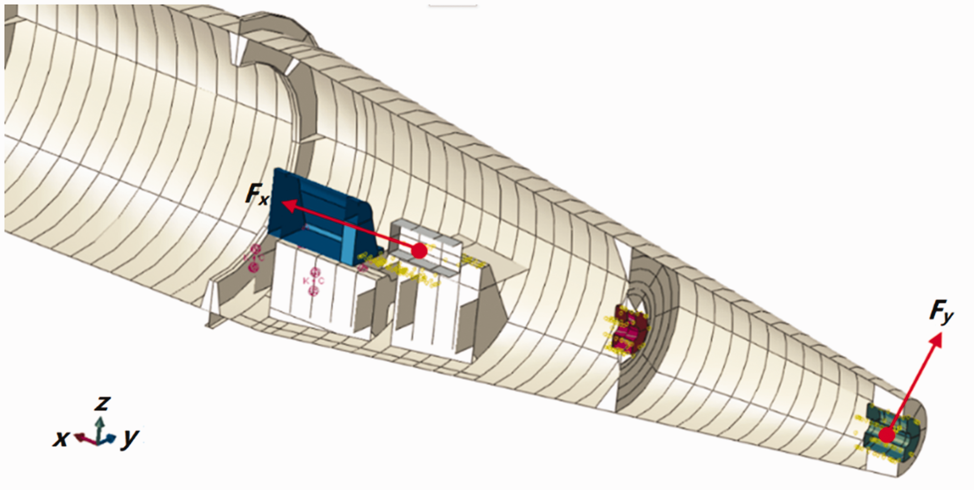
Longitudinal and lateral excitations applied to the submarine hull.
Figure 11(a) shows the longitudinal and transverse responses at the thrust bearing under longitudinal excitation. The peak response frequencies in the longitudinal direction are marked with red dashed lines and tagged as e, f, h and the peak response frequencies in the transverse direction are marked with blue dashed lines and tagged as a, b, c, d, e, f, h, j. It is clear that: (1) under longitudinal excitation, all the longitudinal modes are excited (marked as red e, f, h refer to Figure 9 and Table 4). In the transverse direction, most of the low frequency global modes are excited (marked as blue a, b, c, d, e, f, h, j refer to Figure 9 and Table 4). (2) Due to the asymmetry of the hull structure, the coupled longitudinal and transverse responses are excited under longitudinal excitation, but the amplitudes in the lateral direction are much lower.
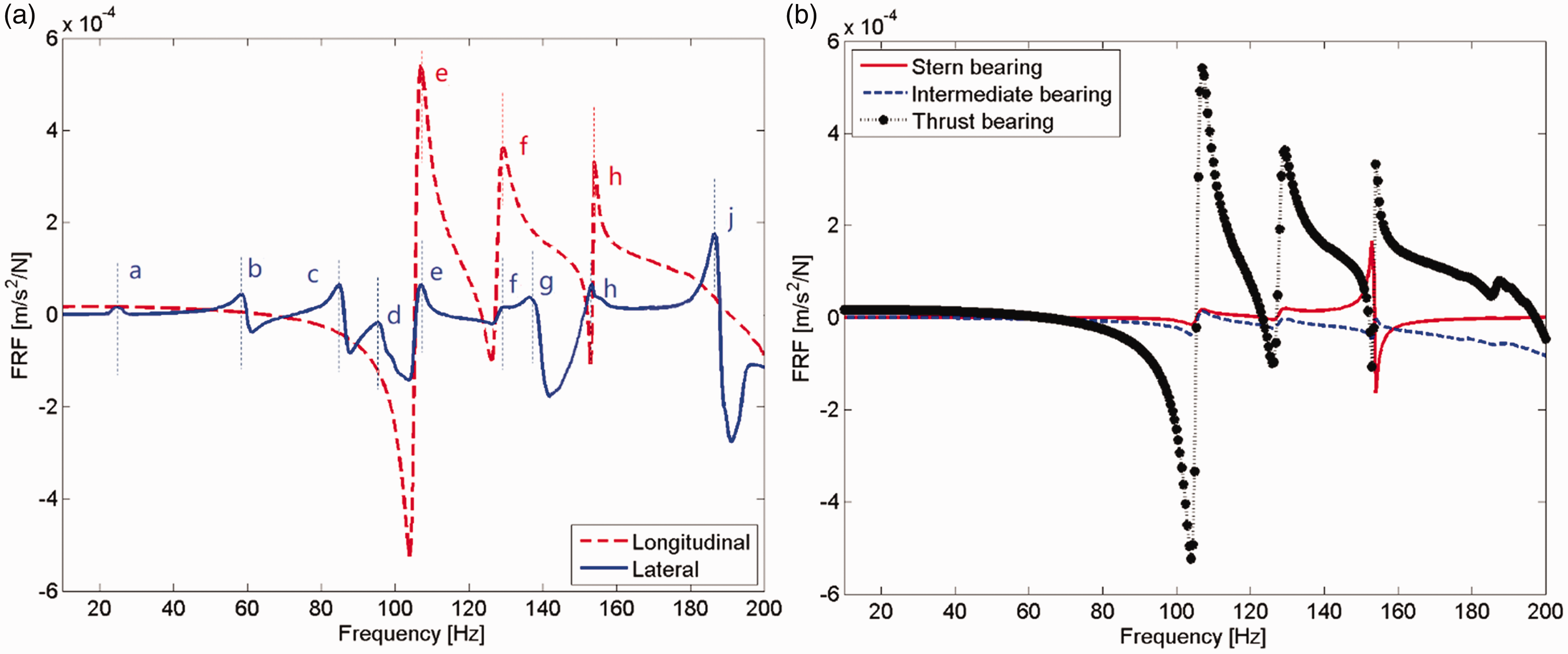
Frequency response functions of the hull under longitudinal excitation applied to the reference point of the thrust-bearing center. (a): longitudinal and transverse responses at the thrust-bearing node; red dashed lines: the peak response frequencies of longitudinal response; red e, f, h: peak response tagging of longitudinal response; blue dashed lines: the peak response frequencies of transverse response; blue a, b, c, d, e, f, h, j: peak response tagging of longitudinal response. (b): Comparison of the longitudinal response at the stern bearing, the intermediate bearing and the thrust bearing.
Figure 11(b) compares the longitudinal responses at the stern bearing, the intermediate bearing and the thrust bearing. We can notice that the longitudinal response at the thrust bearing is much larger than that at the other two bearings, which indicates that the thrust bearing is the main transfer path for longitudinal excitation.
Figure 12(a) plots the longitudinal and transverse responses at the stern bearing node under lateral excitation for a frequency range of 10–200 Hz. The peak response frequencies in the longitudinal direction are marked with red dashed lines and tagged as b, c, e, f, g, j, while the peak response frequencies of the transverse response are marked with blue dashed lines and tagged as a, b, c, d, e, f, g, j. The dynamic characteristics under lateral excitation are quite similar to that under longitudinal excitation. The longitudinal and transverse responses are coupled and the amplitude in the longitudinal direction is lower. However, the peaks are more abundant in longitudinal direction under lateral excitation compared to those under longitudinal excitation, which indicates that the global modes are easier to bring out under lateral excitation. Figure 11(b) compares the transverse responses at the stern bearing, the intermediate bearing and the thrust bearing. We can observe that the amplitude of the transverse response at the stern bearing is much larger than that at the other two bearings, which indicates that the stern bearing is the main transfer path for lateral excitation.
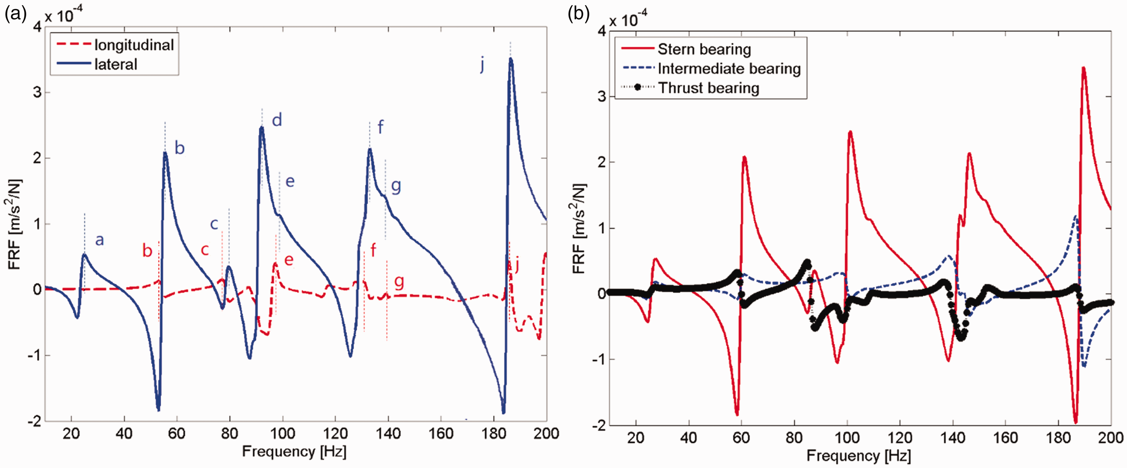
Frequency response functions of the hull under lateral excitation applied to the reference point of the stern bearing center. (a): longitudinal and transverse responses at stern bearing node; red dashed lines: The peak response frequencies of longitudinal response; red b, c, e, f, g, j: peak response tagging of longitudinal response; blue dashed lines: the peak response frequencies of transverse response; blue a, b, c, d, e, f, g, j: peak response tagging of longitudinal response. (b): Comparison of the transverse responses at the stern bearing, the intermediate bearing and the thrust bearing.
Dynamic characteristics of the propeller-shaft-hull system
Figure 13 shows the global modes of the propeller-shaft-hull system in the frequency range of 10–250 Hz. It is clear that most of the global modes are the combination of the hull and the propeller-shaft subsystem, while most of them are dominated by the hull modes. Since the first propeller mode is an out of plane local mode as shown in Figure 13(n), the propeller mode is decoupled from the shaft or the hull and its natural frequency is the same as that of the propeller-shaft subsystem as listed in Table 3.
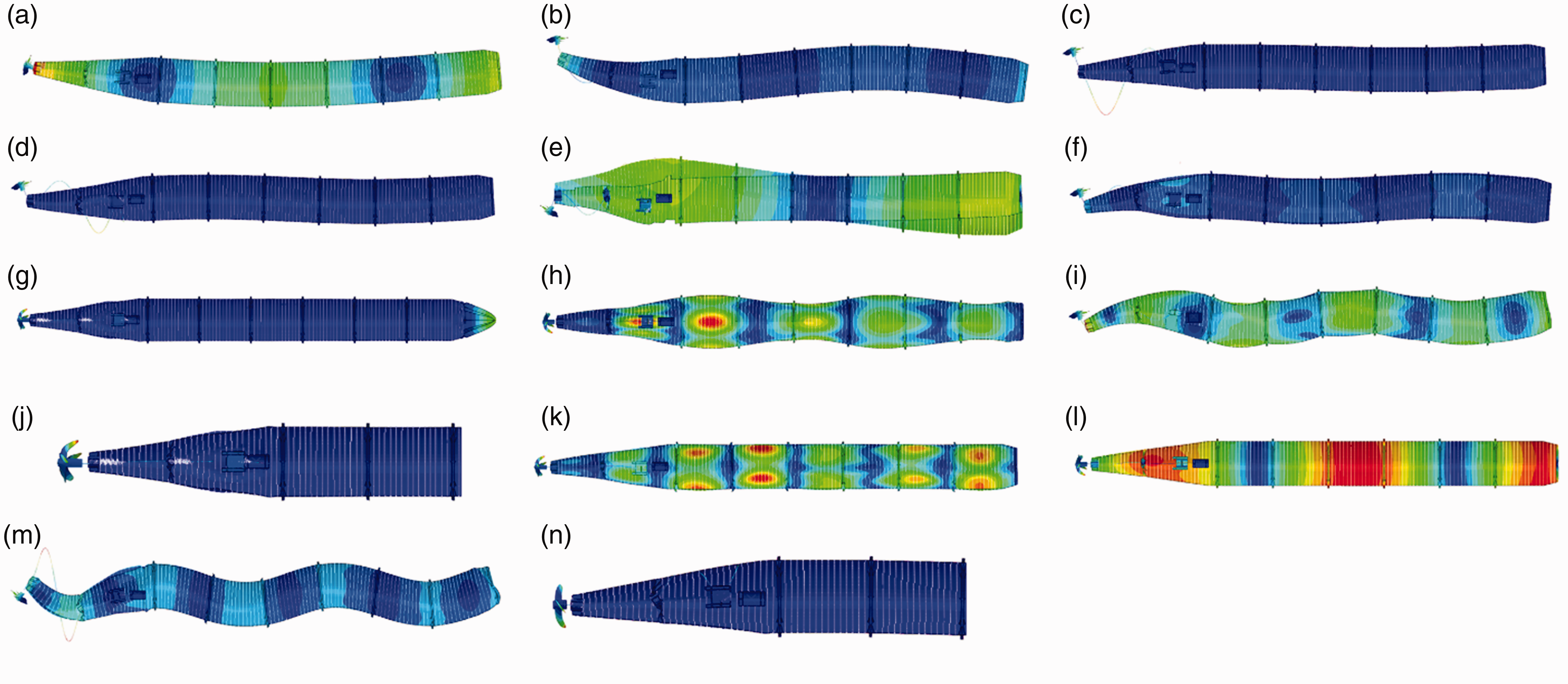
Twelve global modes of the propeller-shaft-hull system in the frequency range of 10–250 Hz. (a): 1st bending mode of hull at 24.6 Hz; (b): 2nd bending mode of hull plus 1st bending mode of shaft at 54.9 Hz; (c): 2nd bending mode of shaft at 59.3 Hz; (d): 3rd bending mode of shaft at 74.4 Hz; (e): 1st torsional mode of hull at 77.9 Hz; (f): 3rd bending mode of hull at 98.0 Hz; (g): 1st longitudinal mode of hull at 104.6 Hz; (h): 2nd bending mode of hull at 132.6 Hz; (i): 4th bending mode of hull at 140.2 Hz; (j): 1st longitudinal mode of shaft at 140.4 Hz; (k): 3rd longitudinal mode of hull at 152.6 Hz; (l): 2nd torsional mode of hull at 156.9 Hz; (m): 5th bending mode of hull at 183.1 Hz; (n): 1st local mode of propeller at 210.6 Hz.
Harmonic longitudinal excitation and harmonic lateral excitation are acting at the propeller hub center with a frequency range of 10–250 Hz. Figure 14(a) plots the longitudinal and transverse responses at the thrust bearing under longitudinal excitation applied to the propeller hub center. The peak response frequencies in the longitudinal direction are marked with red dashed lines and tagged as g, h, j, k, n, while the peak response frequencies of the transverse response are marked with blue dashed lines and tagged as a, b, d, g, h, j, k, m, n. It is clear that: (1) in the longitudinal direction, all the longitudinal modes are excited (marked as red g, h, j refer to Figure 13) and the out of plane local mode of the propeller is excited marked as n in Figure 13). In the transverse direction, the low frequency global modes are all excited (marked as blue a, b, d, g, h, j, k, m, n refer to Figure 13). (2) Due to the asymmetry of the hull structure, the longitudinal and transverse responses are coupled. The longitudinal responses are higher than the transverse responses if the longitudinal excitation is applied, while the transverse responses are higher if the lateral excitation is applied.
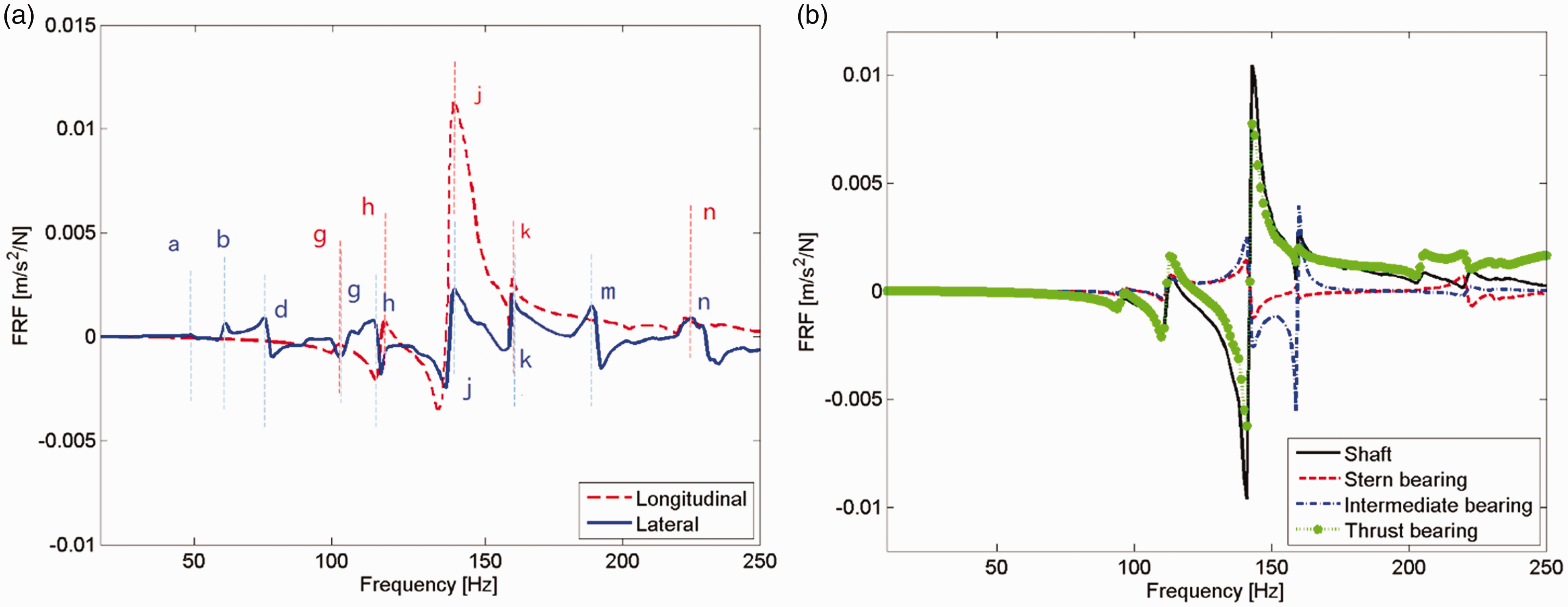
Frequency response functions of the propeller-shaft-hull system under longitudinal excitation applied to the propeller hub center. (a): longitudinal and transverse responses at thrust-bearing node; red dashed lines: the peak response frequencies of longitudinal response; red g, h, j, k, n: peak response tagging of longitudinal response; blue dashed lines: the peak response frequencies of transverse response; blue a, b, d, g, h, j, k, m, n: peak response tagging of the longitudinal response. (b): Comparison of the longitudinal response at shaft node, stern bearing, intermediate bearing and thrust bearing.
Figure 14(b) compares the longitudinal responses at the shaft, the stern bearing, the intermediate bearing and the thrust bearing. Since the longitudinal excitation is directly applied to the shaft, the responses of the shaft are largest. During the load transmission, the amplitude of the longitudinal response at the thrust-bearing node is much larger than that at the other two bearing nodes, which proves that the thrust bearing is the main transfer path for the longitudinal propeller bearing force.
Figure 15(a) shows the longitudinal and transverse responses at the stern bearing under lateral excitation applied to the propeller hub center for a frequency range of 10–250 Hz. The peak response frequencies in the longitudinal direction are marked with red dashed lines and tagged as b, c, d, f, g, j, k, m, n, while the transverse peak response frequencies are marked with blue dashed lines and tagged as a, b, c, d, f, g, i, k, m, n. Similarly, all the longitudinal modes (marked as red g, h, j in Figure 13), the local mode of the propeller (marked as n in Figure 13) and the most of the low frequency lateral modes are excited, but the torsional modes of hull are not evident. In addition, the longitudinal and transverse responses are coupled under lateral excitation, although the amplitude of the longitudinal response is much lower than that of the lateral vibration.
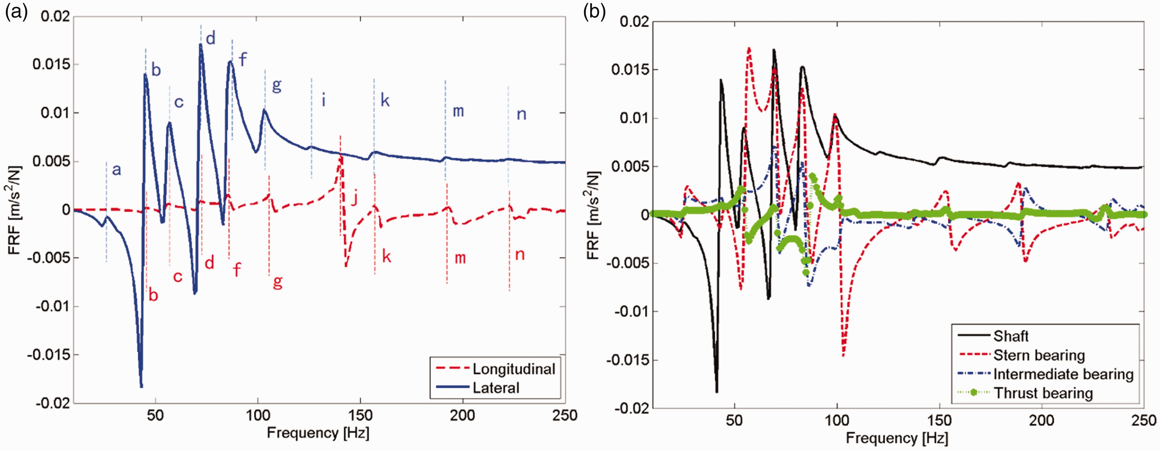
Frequency response functions of the propeller-shaft-hull system under lateral excitation applied to the reference point of the stern bearing center. (a): longitudinal and transverse responses at the stern bearing node; red dashed lines: the peak response frequencies of longitudinal response; red b, c, d, f, g, j, k, m, n: peak response tagging of longitudinal response; blue dashed lines: the peak response frequencies of transverse response; blue a, b, c, d, f, g, i, k, m, n: peak response tagging of longitudinal response. (b): Comparison of the transverse response at shaft, at stern bearing, at intermediate bearing and at thrust bearing.
Figure 15(b) compares the transverse responses at the shaft, the stern bearing, the intermediate bearing and the thrust bearing. We can notice that since the lateral excitation is directly applied to the shaft, the response of the shaft is largest, while the amplitude of transverse response at the stern bearing node is much larger than that at the other two bearing nodes, which proves that the stern bearing is the main transfer path for lateral propeller bearing force.
Associated with ‘Dynamic characteristics of the propeller-shaft subsystem’ section and ‘Dynamic characteristics of the submarine hull’ section, the dynamic characteristics of the propeller-shaft-hull system and the two subsystems show: (1) the natural frequencies of the total system are close to the natural frequencies of the hull or the propeller-shaft substructure. (2) The modes of total system are the combination of the two substructures. If the natural frequency of the total system is close to that of the hull, the mode of the total system is dominated by the hull mode, similar for the propeller-shaft-dominated natural frequencies and modes. If the natural frequency of the total system is close to both of the two substructures, the mode is expressed as the coupled vibration of the propeller-shaft and the hull (such as mode b in Figure 13). (3) When the propeller-shaft substructure is connected to the hull, the natural frequencies of the total system dominated by the hull are slightly decreased compared to that of the hull substructure, indicating that the shaft only give a little contribution to the dynamics of the total system.
Experimental results and comparison
Figure 16 illustrates the structure, the loading and excitation devices, the data acquisition system and the sensor locations of the experimental test-rig. Twelve air springs are used to levitate the test-rig, and the stiffness of the air spring is very low (with a natural frequency of 2.5 Hz). A longitudinal loading device is used as shown in Figure 16(a) to apply a static thrust to the propeller shaft. A vibration exciter integrated in the longitudinal loading device as shown in Figure 16(b) generates the propeller excitation force. Accelerometers are stuck on the hull and the shaft, while acceleration signals are collected using the LMS test-data acquisition system as shown in Figure 16(c). Figure 16(d) plots the locations of the acceleration sensors mounted on the hull, sections 1–8 are on the cylindrical segments and 8 equally spaced three-dimensional accelerometers are used at each section, while sections 9–14 are on the conical segment and 16 equally spaced three-dimensional accelerometers are used at each section. The LMS Test.Lab® geometry of the hull is also drawn. H1–H11 in Figure 16(e) are 11 three-dimensional accelerometers mounted on the shaft. Figure 16(f) shows the mounting locations of the sensors on a single propeller blade. Since the structure of the blades is the same, the blade modal measurement procedure is implemented on a random blade. In addition, an impact hammer is used in testing the propeller blade modes.
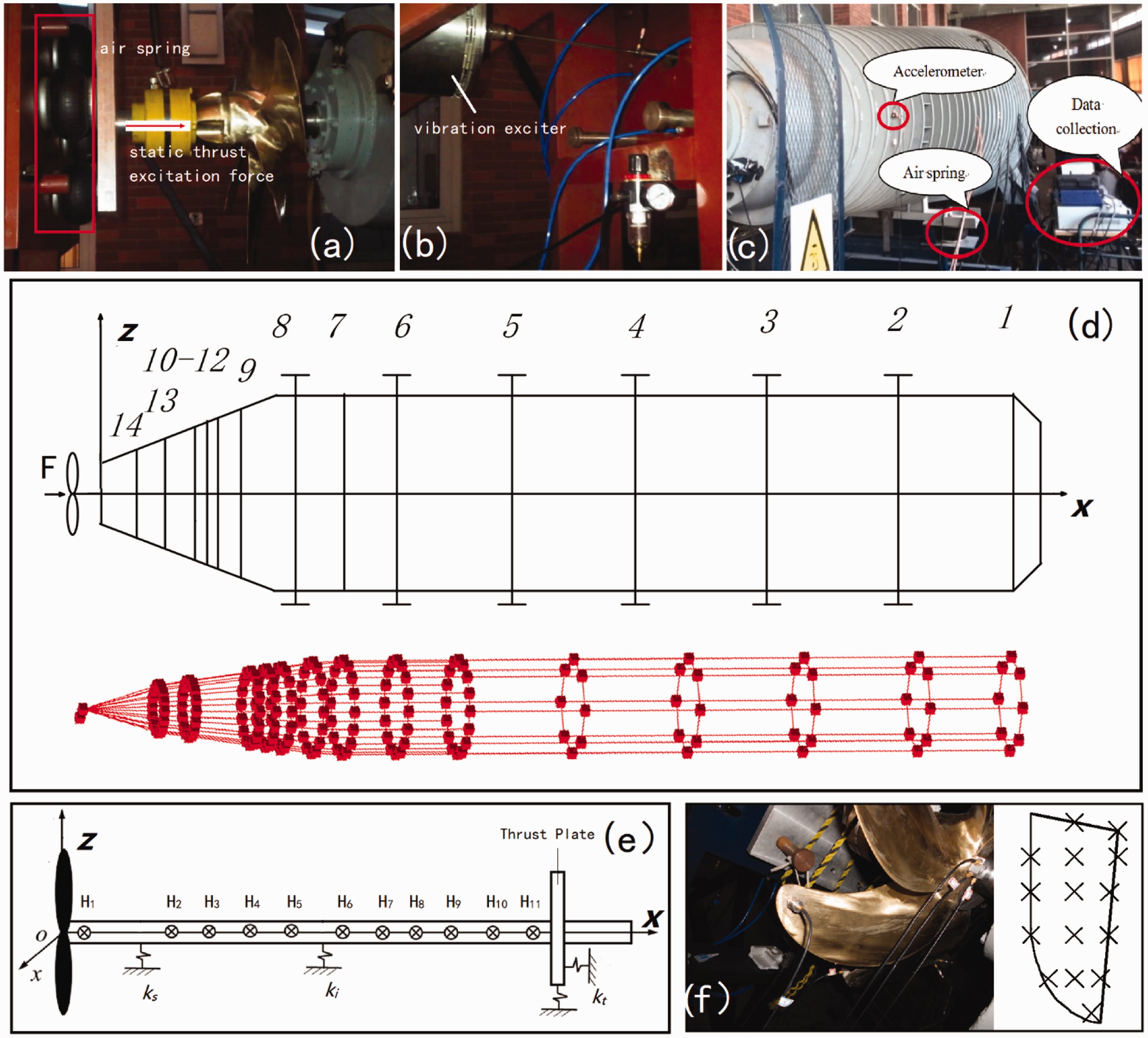
The loading and excitation devices, data acquisition system and the location of the sensors of the experimental test-rig.
Figure 17 compares the global modes of the propeller-shaft-hull system between the numerical simulations and the experimental results. The upper part compares the first three bending, the first torsional and the first longitudinal modes of the propeller-shaft-hull system. The middle part of Figure 17 compares the first three bending and first longitudinal modes of the propeller-shaft substructure. The bottom part compares the first local mode of the propeller blade. In this part, the experimental results are given in top, front and isotropic views. The measured modes are in good agreement with the numerical results. Most of the global modes are the combination of the hull and the propeller-shaft subsystem, except for the first mode of propeller, which is the local mode of the propeller blade itself.
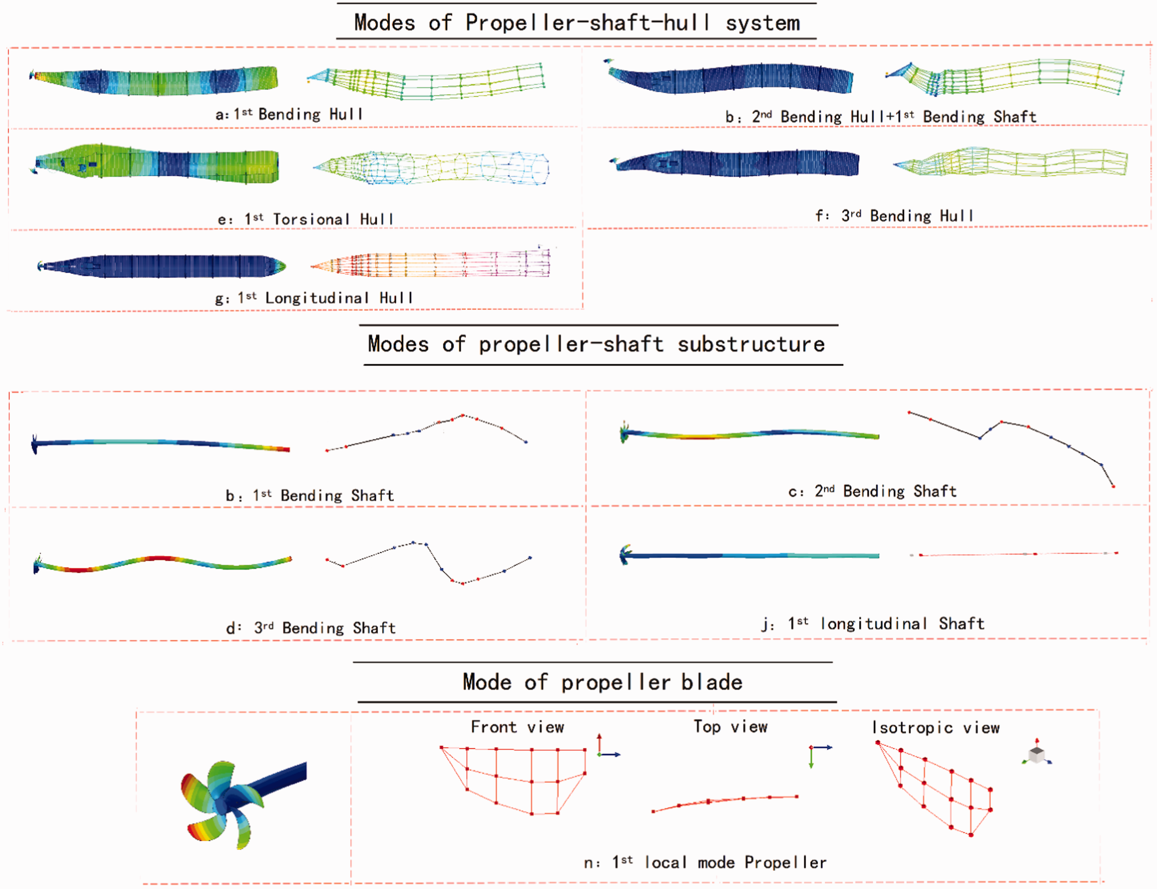
Global modes of the propeller-shaft-hull system, the propeller-shaft substructure and the first-order local mode of the propeller blade. For each mode, left figure: numerical simulation; right figure: experimental result.
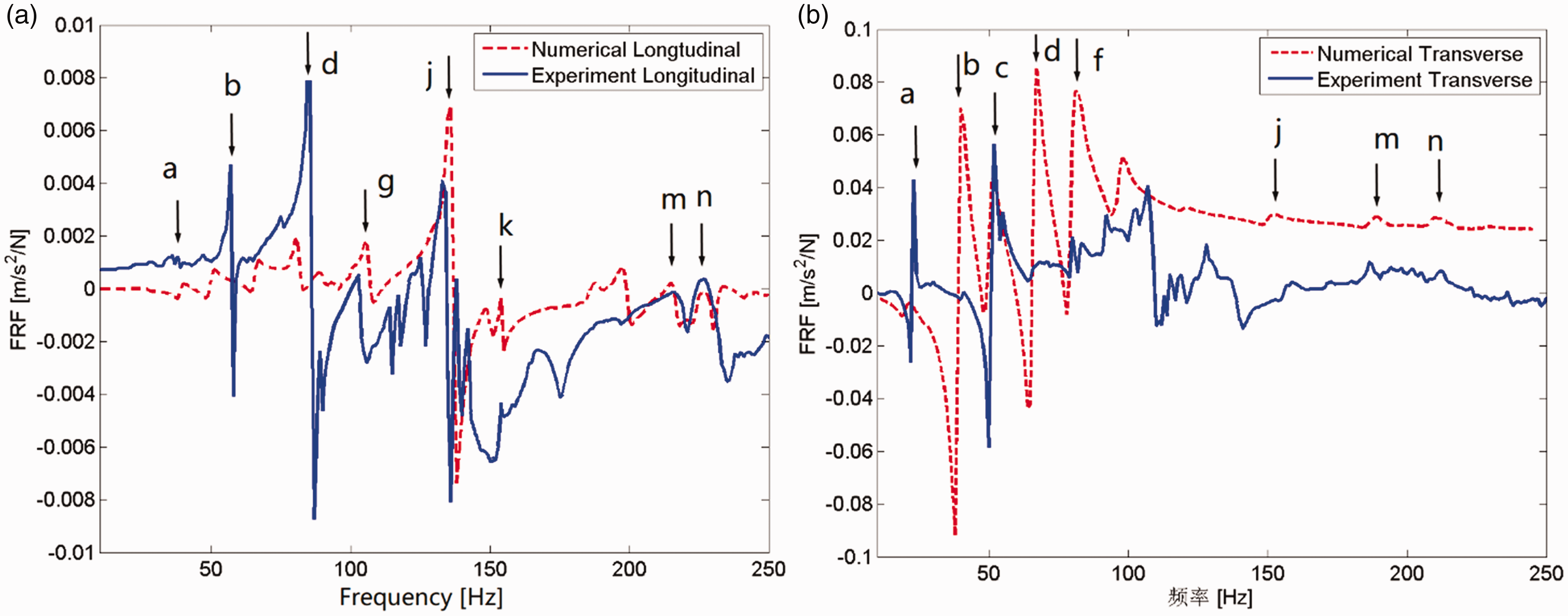
Figure 18 compares the longitudinal and transverse responses of the thrust bearing obtained numerically and experimentally under longitudinal excitation, while Figure 19 compares the responses of the stern bearing under lateral excitation. It is clear that the frequencies at which peaks in the response amplitude occur using FEM are very close to that of the experimental results, and the amplitude peaks are marked using the same letter as shown in Figure 13 and Table 5. Most of the global modes are excited whether under longitudinal or lateral excitation due to the asymmetry of the propeller-shaft-hull system. For an example, we can find amplitude peak j, which is the first longitudinal mode of the shaft, in the transverse response of the stern bearing under lateral excitation. For a certain point, the longitudinal responses are higher if longitudinal excitation is applied, and vice versa. However, the FRFs of the numerical simulations and experiment results are not completely coincident, e.g. some peaks occurred in the numerical simulations are not evident in the experiment results. The differences can be attributed to three reasons: first, the geometry and the material properties of the numerical and experiment model are not exactly the same; second, the excitation applied during the experiment is not an ideal harmonic unit force; last and most important, the damping characteristics of the system are not fully understood, and the structural damping coefficient is assumed to be 1% in our simulation.
Comparison of the longitudinal and transverse responses of the thrust bearing under longitudinal excitation applied to the propeller hub center.
Comparison of the longitudinal and transverse responses of the stern bearing under lateral excitation applied to the propeller hub center.
Comparison of the natural frequencies and their global modes of the propeller-shaft-hull system using ABAQUS in the frequency range of 10–250 Hz.
B: bending; L: longitudinal.
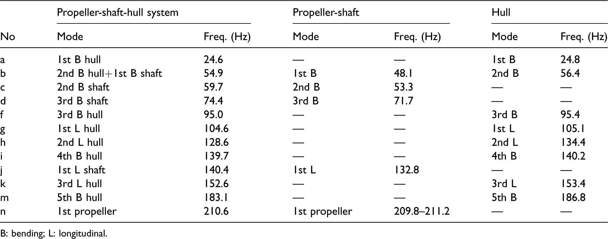
Table 6 compares the natural frequencies and their corresponding modes of the propeller-shaft-hull system between the FEM model and experimental results. The frequencies at which peaks in the response amplitude occur using FEM are close to that of the experimental results, and the maximum error for each mode is less than 7%. Most of the global modes are excited whether under longitudinal or lateral excitation, which reveals the coupling of the longitudinal and transverse dynamic responses.
Comparison of the natural frequencies and their global modes of the propeller-shaft-hull system between experimental and numerical results in the frequency range of 10–250 Hz.
B: bending; L: longitudinal.
Transfer path analysis of the propeller excitation force
Transfer path analysis (TPA) is widely used in various engineering fields, such as to improve noise, vibration and harshness (NVH) problems in automotive engineering by identifying sources and calculating the contribution of each source.35,36 For ships or submarines, TPA studies were triggered by the need to reduce the transmission of engine vibrations in order to make them stealthy. Most of the publications are focused on isolation of ship diesel engines or gas turbines by means of absorbers and decoupling mechanisms37,38 to minimize the transmission through the interfaces. Few papers discussed about the transfer path for propeller excitation, such as Feng et al. 39 established a propulsion shaft model and analyzed the transfer path for longitudinal excitation using the power flow method.
Figure 20 concludes the transfer paths from the propeller to the hull under longitudinal or transverse excitations. The transfer path of the excitation is different for longitudinal and transverse excitations. The longitudinal excitation can only be transferred through the thrust bearing and its base, while the transfer path is more complex for lateral excitation, which includes three paths, namely, the stern bearing, the intermediate bearing and the thrust bearing. In this section, the transfer paths for longitudinal and lateral excitations are both discussed.
The transfer paths from the propeller to the hull under longitudinal and transverse excitations.
Transfer path analysis procedure
The detailed transfer path analysis (TPA) procedures using the power flow method can be established following Feng et al. 39 In the present paper, we will only introduce the principal procedures.
For a harmonic excitation, the steady-state power flow is defined as the average energy in a cycle, which is

Define 
The steady-state power flow through the ith path will be

Assume the impedance at the ith transfer path is 

The power can be finally derived as

Transfer path analysis of longitudinal and lateral excitations
The transfer path is analyzed using a harmonic excitation applied to the propeller hub center in a frequency range of 10–250 Hz. Figure 21 plots the input power and transmitted power through thrust bearing under longitudinal excitation. It is clear that both the input power and the transmitted power are low in the low-frequency range (10–100 Hz). This is because the system longitudinal stiffness is relatively high compared to the bending stiffness. In the middle frequency range (100–250 Hz), the input power and the transmitted power are sharply increased, especially at frequency 104 Hz(g), 140 Hz(j), 152 Hz(k) and 210 Hz(n). According to ‘Dynamic characteristics of the propeller-shaft-hull system’ section, they denote the first longitudinal mode of the hull, the first longitudinal mode of the shaft, the third longitudinal mode of the hull and the first local mode of the propeller. At these frequencies, the system impedance is low which causes high input and transmitted power.
Input and transmitted power through thrust bearing under longitudinal excitation applied to the propeller hub center.
Figure 22 plots the input power and transmitted power through the stern bearing, the intermediate bearing and the thrust bearing under lateral excitation. Figure 22(a) compares the input power and total transmitted power. It is clear that input power and the transmitted power are higher in the low-frequency range (10–100 Hz) compared to that under longitudinal excitation. This is because the system bending stiffness is much lower compared to the longitudinal stiffness. There are many amplitude peaks, which refer to the natural frequencies of the coupled longitudinal and transverse vibrations of the propeller-shaft-hull system. Figure 22(b) compares the transmitted power through the stern bearing, the intermediate bearing and the thrust bearing, individually. We can observe that the power at the stern bearing is largest, which reveals that the stern bearing is the most important transfer path for lateral excitation.
Input and transmitted power through the thrust bearing under longitudinal excitation applied to the propeller hub center. (a): Comparison of the input power and the total transmitted power; (b): comparison of the transmitted power through the stern bearing, the intermediate bearing and the thrust bearing.
Figure 23 compares the input power and the total transmitted power under longitudinal and lateral excitation applied to the propeller hub center. It is clear that: (1) the input power and the total transmitted power are higher in the low-frequency range (10–100 Hz) for lateral excitation, while the input power and the total transmitted power are much higher in the middle frequency range (100–250 Hz) for longitudinal excitation. The demarcation is the first longitudinal natural frequency of the hull (104 Hz). This is because the system bending stiffness is much lower compared to the longitudinal stiffness. (2) There are more peaks for both the input and the total transmitted power under lateral excitation than those under longitudinal excitation, which means the coupled vibrations are easier to be excited under lateral excitation.
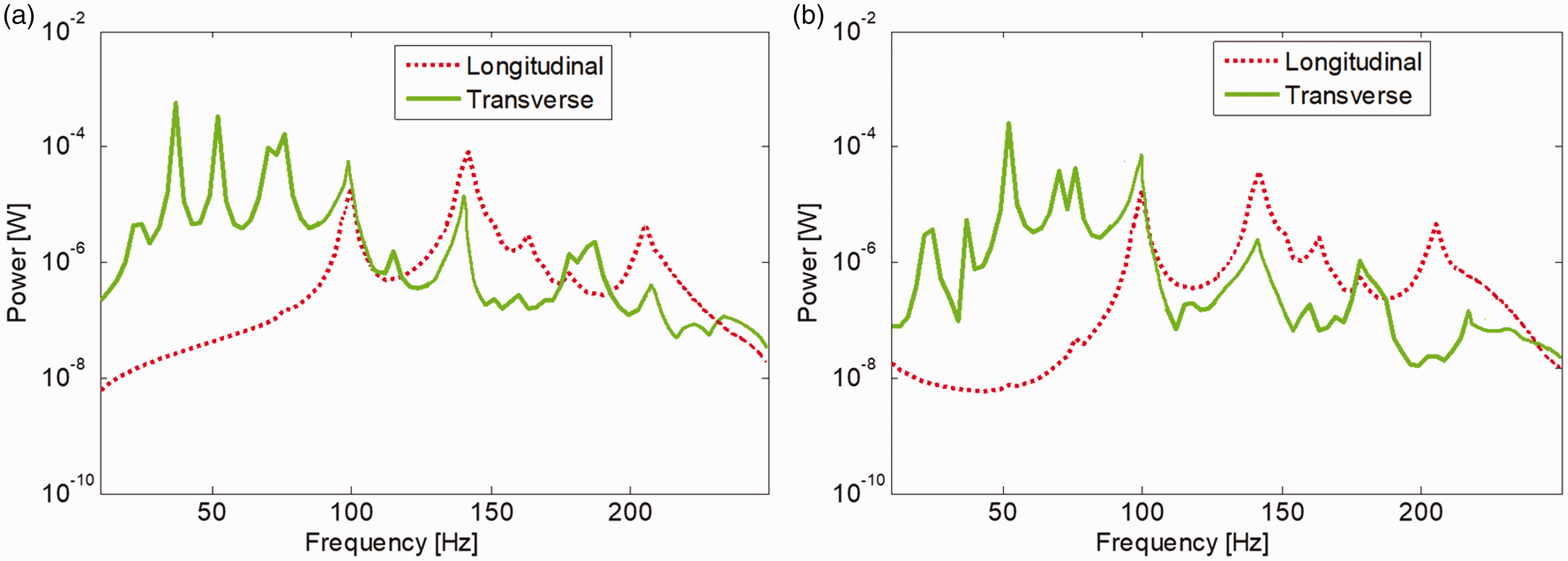
The input and the total transmitted power under longitudinal and transverse excitation applied to the propeller hub center. (a): Comparison of the input power; (b): comparison of the total transmitted power.
Transfer path analysis using different bearing stiffness
Since the thrust bearing is the dominant transfer path under longitudinal excitation, only the longitudinal stiffness of the thrust bearing is changed in our study. Three longitudinal stiffness values are chosen, which are ktx1 = 1 × 10⁷ N/m, ktx2 = 1 × 10⁸ N/m, and ktx3 = 1 × 10⁹ N/m.
Under lateral excitation, three bearing stiffness are all varied. For the stern bearing, the parameters are ksy1 = 1 × 10⁶ N/m, ksy2 = 1 × 10⁷ N/m, and ksy3 = 1 × 10⁸ N/m; for the intermediate bearing, the parameters are kiy1 = 1 × 10⁶ N/m, kiy2 = 8 × 10⁶ N/m, and kiy3 = 1 × 10⁸ N/m; for the thrust bearing, the parameters are kty1 = 1 × 10⁶ N/m, kty2 = 2.5 × 10⁷ N/m, and kty3 = 1 × 10⁸ N/m.
Figure 24 compares the input and the total transmitted power under longitudinal excitation with different thrust-bearing stiffness. We can notice that: (1) all the longitudinal modes are excited, e.g. g, k are the longitudinal modes of the hull, j is the first longitudinal mode of shaft and n is the first local mode of the propeller. (2) With the increasing of the thrust-bearing stiffness, the first longitudinal natural frequency of the shaft is changed enormously (j from 120 Hz to 150 Hz), but the dominant natural frequencies of the global hull modes and the local modes of the propeller are barely changed (g, k and n). It indicates that the change of the longitudinal stiffness of the thrust bearing mainly affects the longitudinal dynamics of the shaft, while has little influence on the dynamic characteristics of the hull.
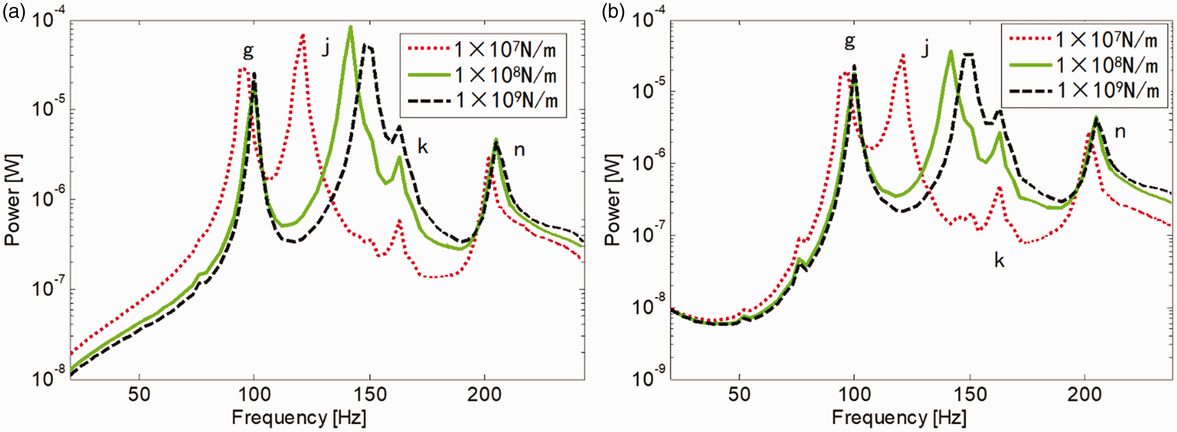
Comparison of power of propeller-shaft-hull system under longitudinal excitation applied to the propeller hub center with different thrust-bearing stiffness. (a): Comparison of the input power; (b): comparison of the total transmitted power.
Figure 25 compares the input and the total transmitted power under lateral excitation with different stern, intermediate and thrust-bearing stiffness. We can also notice that: (1) not only the lateral modes but also the longitudinal modes are excited, the coupled vibrations are easier to be excited under lateral excitation. (2) With the increase of the stern bearing stiffness, the bending natural frequencies related to the shaft have changed considerably; however, the natural frequencies of the dominant hull global modes are barely changed. It reveals that the change of the lateral stiffness of the stern bearing contributes little to the dynamic characteristics of the hull. (3) For the intermediate and the thrust bearings, the input and the transmitted power change a little by varying the stiffness of these two bearings. It means the intermediate and the thrust bearings are not the dominant path for lateral vibration transmitting, and it is more effective to optimize the stern bearing stiffness to improve the vibration characteristics of the system under lateral excitation.
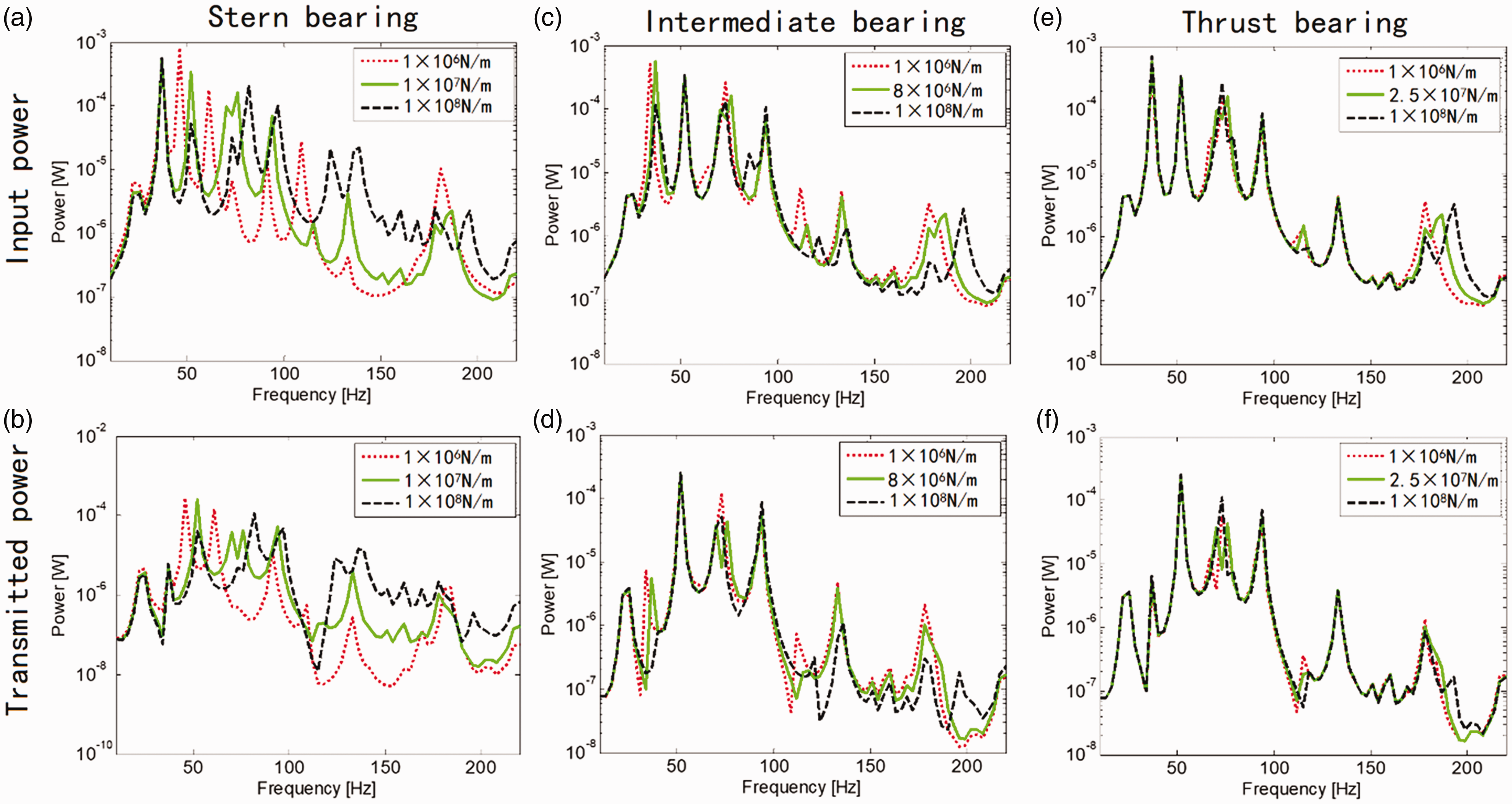
Comparison of power of propeller-shaft-hull system under lateral excitation applied to the propeller hub center with different bearing stiffness. Left column (a), (b): change stern bearing stiffness; middle column (c), (d): change intermediate bearing stiffness; right column (e), (f): change thrust-bearing stiffness.
Conclusion
This paper studies the coupled transverse and longitudinal vibrations of a submarine propeller-shaft-hull system using the FEM. The dynamic characteristics of the propeller-shaft system, the hull and the total system are analyzed and compared between the numerical simulations and experiment results. Several conclusions can be achieved.
First, the simulated frequencies at which peaks in the response amplitude occur of the propeller-shaft, the hull and the propeller-shaft-hull system using FEM are very close to the experimental results. The maximum error for each mode is less than 7%, the modes and the FRFs using either method are in good agreement. Second, due to the asymmetry of the hull structure, most of the low-frequency global modes are excited either under longitudinal or lateral excitation, which reveals the coupling of the longitudinal and transverse dynamic characteristics. Third, the modes of the propeller-shaft-hull system are the coupled vibrations of the hull, the shaft, and the propeller. Some of them are dominated by the hull, while others are dominated by the propeller-shaft. Fourth, the thrust bearing is the dominant transfer path for low frequency longitudinal excitation from propeller to the hull, while the stern bearing is the dominant transfer path for transverse excitations. Last, with the increasing of the stiffness of stern bearing or the thrust bearing, only the bending or the longitudinal natural frequencies related to the shaft have enormously changed. It indicates that the change of the bearing stiffness mainly affects the dynamic characteristics of the shaft, while has little influence on the dynamics of the hull.
Footnotes
Declaration of conflicting interests
The author(s) declared no potential conflicts of interest with respect to the research, authorship, and/or publication of this article.
Funding
The author(s) disclose receipt of the following financial support for the research, authorship, and publication of this article: This work was supported by the National Natural Science Foundation of China (51405292).