
Abstract
The main goal of the study is to apply the structural intensity method to analyze the effects of positions of the main-mount and the sub-mount on the vibrational energy flow transmission characteristics in aero-engine casing structures, so as to attenuate the vibration of the casing and the whole aero-engine. Structural intensity method, indicating magnitude and direction of the vibrational energy flow, is a powerful tool to study vibration problems from the perspective of energy. In this paper, a casing-support-rotor coupling model subjected to the rotor unbalanced forces is established by the finite element method. Formulations of the structural intensity of a shell element and the structural intensity streamline are given. A simulation system consisting of the finite element tool and the in-house program is developed to carry out forced vibration analysis and structural intensity calculation. The structural intensity field of the casing is visualized in the forms of vector diagram and streamline representation. The vibrational energy flow behaviors of the casing at the rotor design rotating speed are analyzed, and the vibrational energy flow transmission characteristics of the casing with different axial positions of the main-mount and the sub-mount are investigated. Moreover, some measures to attenuate the vibration of the casing are obtained from the numerical results, and their effectiveness is verified in the frequency domain and the time domain. The results shed new light on the effects of the mount positions on the vibration energy transmission behaviors of the casing structure. The structural intensity method is a more advanced tool for solving vibration problems in engineering. Furthermore, it may provide some guidance for the vibration attenuation of the casing and the whole aero-engine.
Keywords
Introduction
As aero-engine’s thrust–weight ratio is demanded to be higher and higher, the casing structure is designed to be as thin as possible to reduce the weight of the whole engine. Therefore, the stiffness of the casing is reduced, causing the vibration of the casing to be more easily excited. Since the casing carries main loads of aero-engine, its vibration will certainly give rise to whole aero-engine’s vibration.1–3 Considering the fact that most of aero-engine’s fault is caused by the vibration overrun, 4 the issues of aero-engine casing’s vibration attenuation should be paid more attention to, so as to attenuate the whole aero-engine’s vibration and increase aero-engine’s safety and reliability.
General procedure for assessment of dynamic properties of the casing and shell structure implies modal analysis, that is, determination of natural frequencies and mode shapes, which is further used for updating the finite element model of an assembled aero-engine casing to reduce the response of the aero-engine, 5 developing optimum designs for cylindrical shell structures, 6 and so on. Recently, with the continuous improvement of the requirements for aero-engine safety and reliability, it is indispensable to assess the nonlinear dynamic responses of the casing. Therefore, the nonlinear vibration characteristics of the casing caused by nonlinear bearing and squeeze-film forces,7,8 blade-casing rubbing fault,9,10 and dry friction 11 are investigated by some researchers, and some measures to attenuate the vibration of the casing are also given in this field. In addition to the above factors, the mount position is also a major factor affecting the vibration of the casing and the whole aero-engine. Mount position variation can be made for many reasons, such as force transmission route shortening, stiffness enhancing, and so on. Different mount positions have different force transmission routes on the casing, resulting in different vibration conditions. Therefore, it is necessary to study the influences of mount positions on the vibration of casings. So far, most of studies about the mount have been concerned with mount structure design,12,13 fatigue life estimation, 14 and so on. One study by Qu 15 investigated the effect of the mount stiffness on the coupling vibration between the stator and the rotor, and the concept of rotating-static coupling factor is put forward to assess the influence of mount stiffness on coupling vibration. But for now, what remains poorly understood is the effect of mount positions on the casing vibration propagation characteristics, especially that on the vibration energy transmission characteristics in casing structures, which is still a blank in this field.
The studies mentioned above are mainly based on the traditional vibration analysis method, which usually assesses the vibration level by amplitude. Since the propagation of vibration in structure is essentially the transmission of vibration energy, it is necessary to investigate the vibration propagation characteristics of the casing from the perspective of vibration energy. Structural intensity method is an advanced and powerful tool for predicting and assessing the magnitude and direction of vibrational energy flow in any elastic body. The concept of structural intensity was introduced in 1970s and extended the vector acoustic approach to energy flow in structure-borne sound field.16–18 Pavic 17 has developed the structural intensity formulations leading to a growing interest in this field. Since the structural intensity combines forces with velocities indicating magnitude and direction of vibrational energy flow at any point of a structure, its streamline representations can offer full information of vibration energy transmission paths, 19 and the structural intensity field can display the information about the dissipation of vibrational energy throughout the structure. 20 The interest in assessing the structural intensity of a certain structure has become attractive thanks to its capability to offer this valuable information. 21 This method, therefore, has been used for several years as a tool for the studies of vibration energy distribution and transmission characteristics for some simple structures, such as beams, 22 plates,23–25 and cylindrical shells. 26 But for some complex structures such as aero-engine casing structures subjected to the rotor unbalanced forces, the related research is still quite little.
Therefore, the structural intensity method is applied to the field of aero-engines to visualize the structural intensity fields of the casing subjected to the rotor unbalanced forces, and the effects of mount positions on vibration energy transmission characteristics in aero-engine casing structures are analyzed, so as to attenuate the vibration of the casing and the whole aero-engine. Utilizing the structural intensity method shines new light on this study. A casing-support-rotor coupling model subjected to rotor unbalanced forces is established by finite element method in this paper. Numerical examples include structural intensity analysis of this coupling model with different axial positions of the main-mount (M-M) and the sub-mount (S-M). The structural intensity fields of the casing are visualized in the form of vector diagram and streamline representation, and the vibrational energy flow transmission characteristics of the casing are analyzed. Some measures to attenuate the vibration of the casing are obtained from the numerical results, and their effectiveness is verified in the frequency domain and the time domain. Moreover, the total structural intensity of the casing is decomposed into its components carried by different vibration waves, and the structural intensity fields of these components are also analyzed in a mathematical and numerical way for a better understanding of their transmission characteristics.
Theoretical background
Structural intensity formulations of shell element
Vibrational energy flow per unit area and unit time of a dynamically loaded structure is defined as the structural intensity.
27
The instantaneous structural intensity is a time-dependent vectorial quantity representing energy density change in a given infinitesimal volume. Its ith component in the time domain can be defined as
28

For a steady-state vibration at single frequency, the complex structural intensity in the frequency domain can be obtained by performing the Fourier transform on equation (1).

For shell element, since the stresses are usually determined as stress resultant of the mid-surface and the integration is carried out over the thickness, the structural intensity of shell element represents vibrational energy flow per unit width and unit time, which can be expressed in terms of internal forces, moments, translational displacements, and rotational displacements, obtained from forced vibration analysis. The instantaneous structural intensity for the shell element mid-surface lying in the x–y plane shown in Figure 1 is given by the following expressions
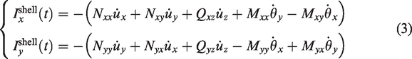
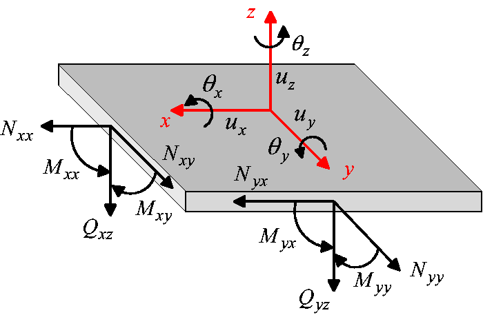
Forces, moments, and displacements for shell element.
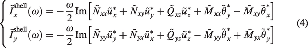
By the Fourier transformation, the structural intensity of shell element in the frequency domain can be expressed as follows
Streamline representations of structural intensity field
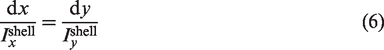
The structural intensity field of shell elements is a two-dimensional (2D) vector field. Streamline technique is a useful tool to display transmission or flow characteristic of a vector field. In the flow field, the streamline technique displays the flow as lines everywhere parallel to the velocity vectors, and the relative spacing of the lines indicates the speed of the flow. Analogous to the definition of streamlines in the flow field, the structural intensity streamlines can be expressed as follows
29

Calculation of structural intensity
In this study, the structural intensity calculation is performed using the developed simulation system consisting of the finite element tool and the in-house program. The former is used for finite element modeling and forced vibration analysis, and the latter is used for structural intensity calculation. The calculation process of this simulation system is shown in Figure 2. When the forced vibration analysis is completed, the in-house program is invoked by the finite element tool and reads necessary information (relationship between node and element, translational and rotational displacements, internal forces at element center, etc.) from the finite element tool output files. The structural intensity is calculated after transforming internal forces and moments into global coordinate system and evaluating displacements at element center using nodal displacements. After that, the calculated structural intensity vectors and other useful data are exported into file system in the form suitable for drawing vector diagrams and streamline representations.
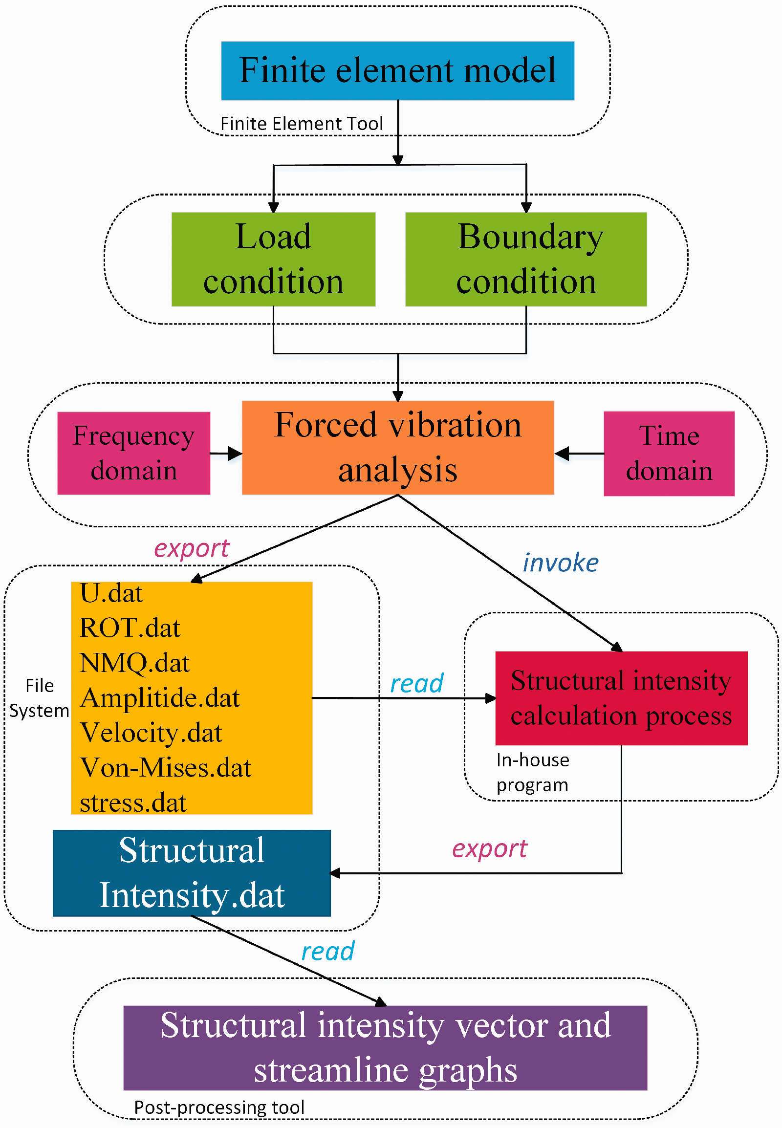
Flowchart for structural intensity calculation. ROT: rotaional displacements; NMQ: internal forces, moments, and external shear forces.
Calculation model—casing-support-rotor coupling model
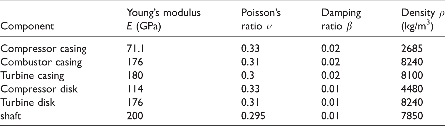
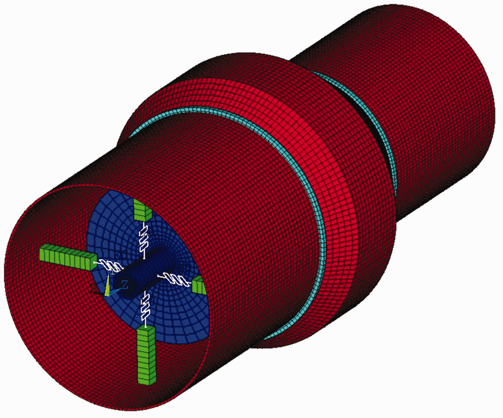
In this study, a casing-support-rotor coupling model subjected to rotor unbalanced forces is established to simulate the aero-engine casing structure and its vibration loads, as shown in Figure 3. In this model, the rotor design rotating speed is 28,000 r/min, and the casing structure contains three parts: compressor casing, combustor casing, and turbine casing, which are combined by the casing flanges, and the whole casing structure is fastened by two M-Ms and one S-M. These two M-Ms are, respectively, set up on the left and right side (±90°) of the combustor casing, which have all degrees of freedom restrained, and this one S-M is set up on the top (0°) of the compressor casing, which has only radial degree of freedom restrained. This coupling model has two supporting frames to hold bearings and transmit vibration loads through the supports. Each supporting frame has four supports circumferentially equispaced on the casing. The supporting frame 1 is set up on the compressor casing, and the supporting frame 2 is set up on the turbine casing. Moreover, the material damping is taken into consideration in each component of this coupling model, which is defined by the damping ratio. The damping ratios are considered as constant stiffness matrix coefficients for the materials of different components to create the damping matrix in the computing process. The structure parameters of this coupling model are listed in Table 1, and the material properties are listed in Table 2.
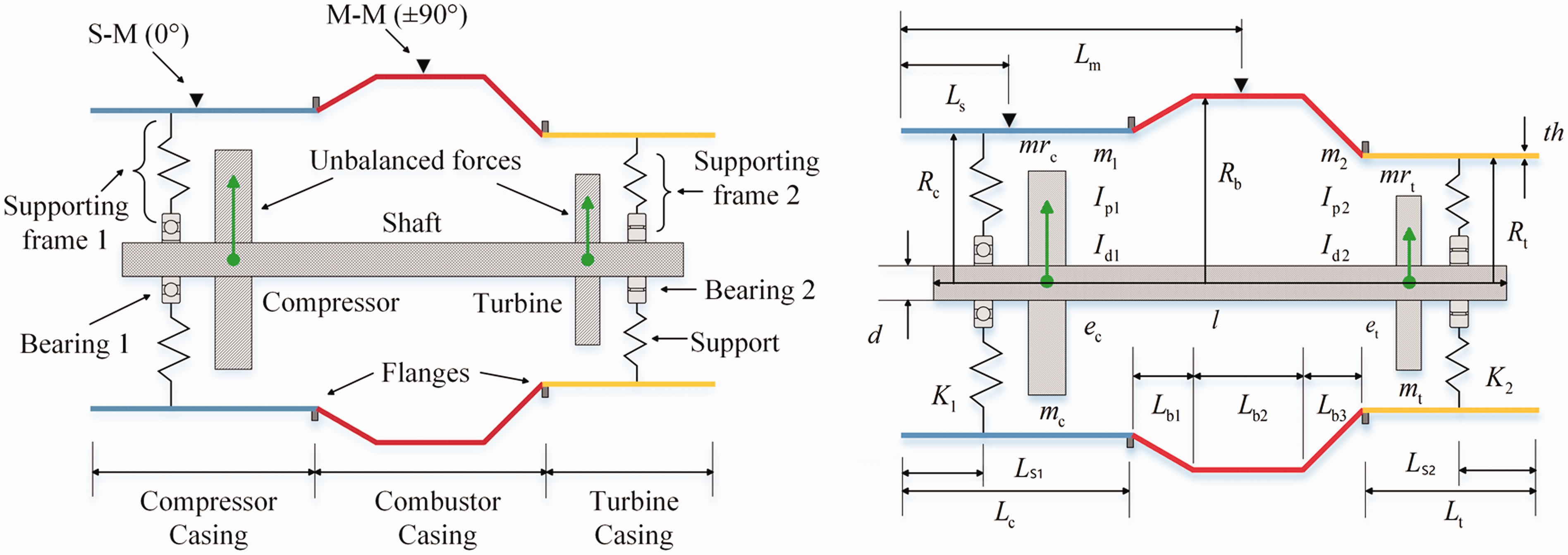
The casing-support-rotor coupling model. M-M: main-mount; S-M: sub-mount.
Structure parameters of casing-support-rotor coupling model.
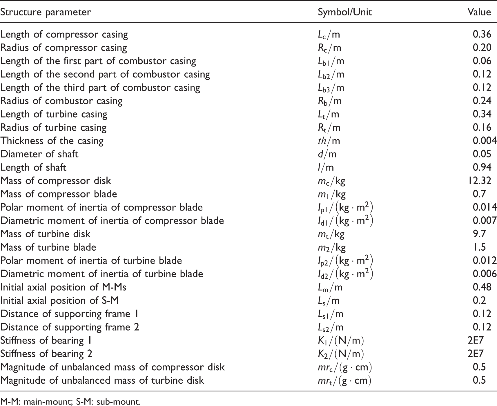
M-M: main-mount; S-M: sub-mount.
Material properties.
The finite element model, which is a combination of different types of elements, is shown in Figure 4. Since the thickness of aero-engine casing is far less than its radius, the casing can be considered as the elastic, thin-walled cylindrical shell structure. Moreover, the shaft and the disks are simulated by solid elements; the blades are simplified by mass elements; the bearings and supporting frames are simulated by spring elements and link elements, respectively. The rotor unbalanced forces act on the centroids of the compressor blisk and the turbine blisk, and they are in-phase. The excitation frequency is 466.67 Hz, which is consistent with the frequency of the design rotating speed. Especially in the transient forced vibration analysis, the rotor unbalanced force is simulated by the transient tabular force, 30 which is decomposed into two transient sinusoidal forces at the centroid of the blisk in two orthogonal directions (x and y directions). In these two forces, the rotor rotating speed and the unbalanced mass of the blisk are taken into consideration.
Finite element model of casing-support-rotor coupling model.
To display the numerical results directly and clearly, the whole casing structure is expanded along the circumferential direction by the in-house program, and the results coordinate of calculated structural intensity is accordingly changed as well. Therefore, this casing is paved into a 2D plane, as shown in Figure 5. The red elements denote the joints between the casing and the supporting frame 1, the blue elements denote the joints between the casing and the supporting frame 2, the yellow elements denote the casing flanges, the green elements denote the M-Ms, and the black element denotes the S-M.
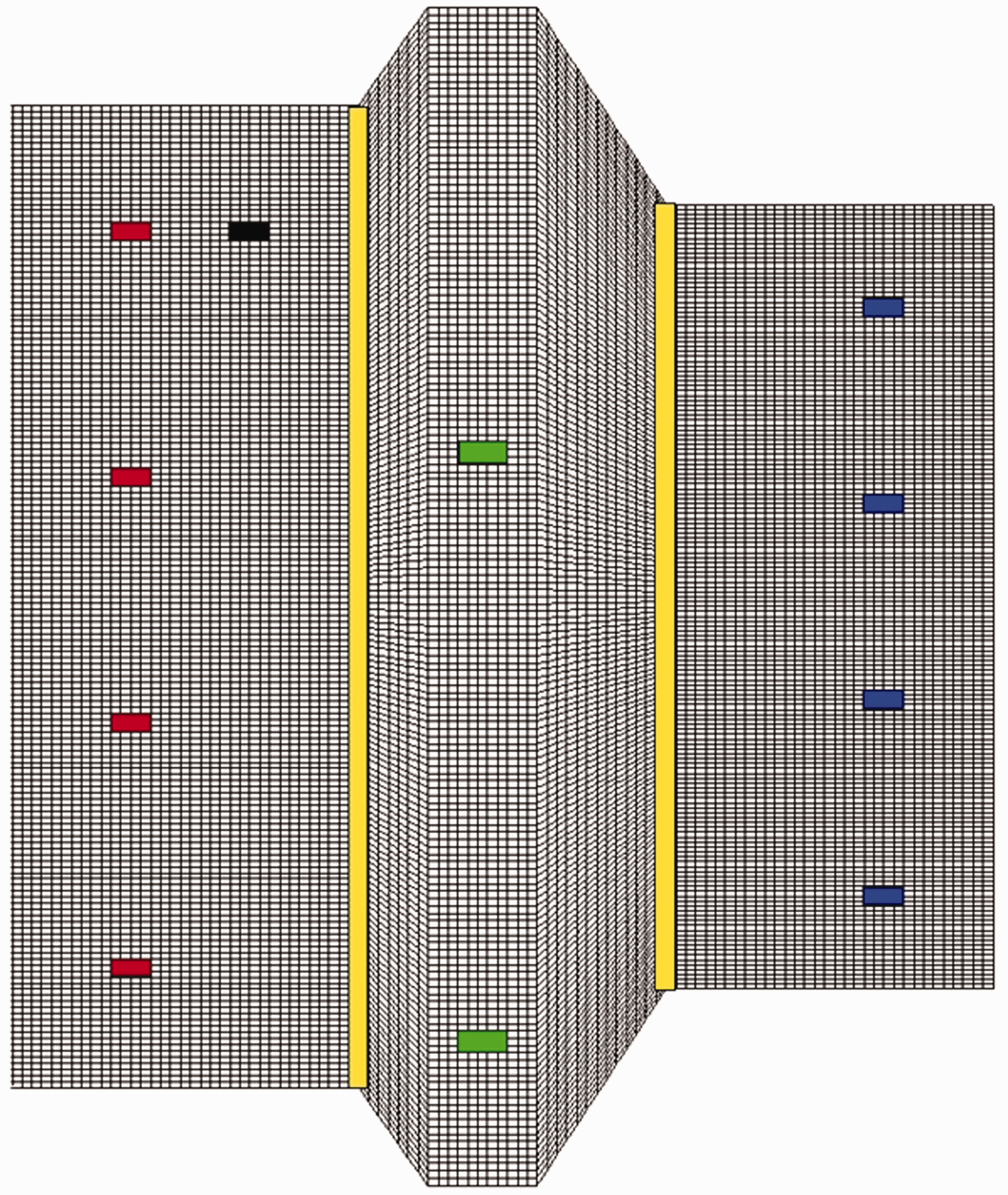
The schematic diagram of the casing expanded along the circumferential direction.
Results and discussion
In this section, the vibrational energy flow transmission characteristics of the casing with different axial positions of the M-M and the S-M are analyzed in the frequency domain, and some measures to attenuate the vibration of the casing are obtained from the numerical results, and their effectiveness is verified in the frequency domain and the time domain. In particular, the effect of the M-M on the vibrational energy flow transmission is analyzed in the time domain.
Due to the design requirements of rotor dynamics and the application of the squeeze film dampers, the rotor can smoothly pass the critical speeds. 31 Therefore, this study only focuses on the vibration of the whole aero-engine at the rotor design rotating speed (at the frequency of 466.67 Hz).
Effects of mount positions on vibrational energy flow
Firstly, the structural intensity field of the casing with the initial positions of the M-Ms and the S-M is calculated at the rotor design rotating speed in the frequency domain, and it is visualized in the forms of scalar and vector diagrams and streamline representation, as shown in Figure 6. From this figure, the pattern of the vibrational energy flow can be seen clearly. The positions of the vibration energy sources (red circle) and sinks (yellow circle) can be identified for the casing, which are the joints between the supports and the casing. The main flow of the vibration energy is in a direct path from the source to the sink. The vibration energy spreads out in different directions from the source on the compressor casing due to the high input energy from the supports. Most of the vibration energy can pass through the flanges and transmit from the compressor casing to the turbine casing, which may easily induce the vibration of whole casing.
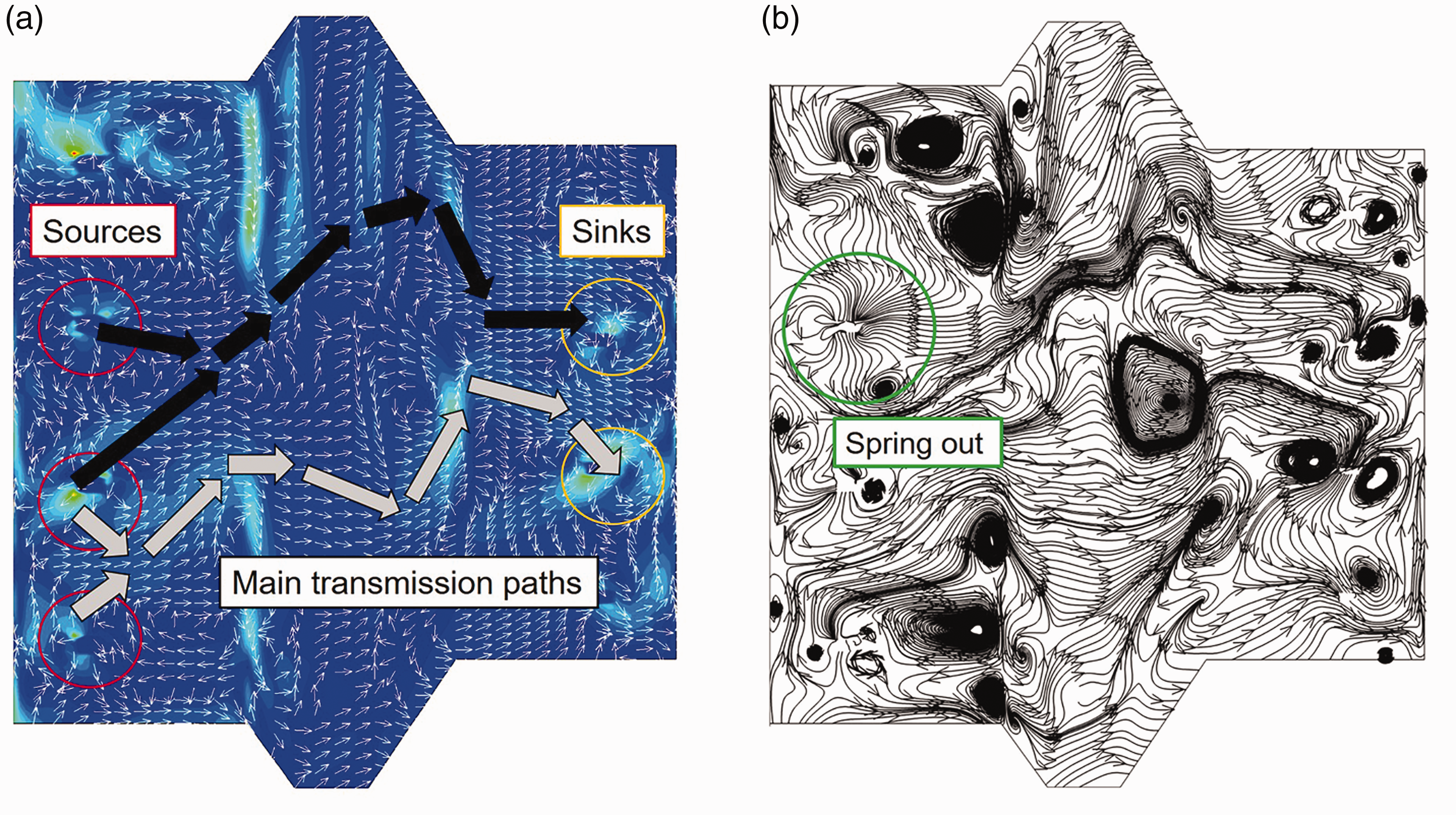
The structural intensity field of the casing at the rotor design rotating speed (at the frequency of 466.67 Hz): (a) scalar and vector diagrams and (b) streamline representation.
Based on the initial mount positions, the axial positions of the M-Ms and the S-M are changed at equal spacing along the length of whole casing structure, respectively. When the M-M axial position is changed, the S-M position stays unchanged, and vice versa. Moreover, the in-house program enables decomposition of total structural intensity (SI-tol) into its components, which are longitudinal wave structural intensity (SI-long), shear wave structural intensity (SI-shear), flexural wave structural intensity (SI-flex), and twist wave structural intensity (SI-twist), and the effects of mount axial positions on these different structural intensity components are analyzed as well. The results are plotted in line charts as shown in Figure 7. Each data point in these two line charts represents the average value of the structural intensity of the casing. In these line charts, the compressor casing part occupies the scope ranged from 0 m to 0.36 m in axial direction, the combustor casing part occupies the scope ranged from 0.36 m to 0.66 m, and the turbine casing part occupies the scope ranged from 0.66 m to 1.0 m.
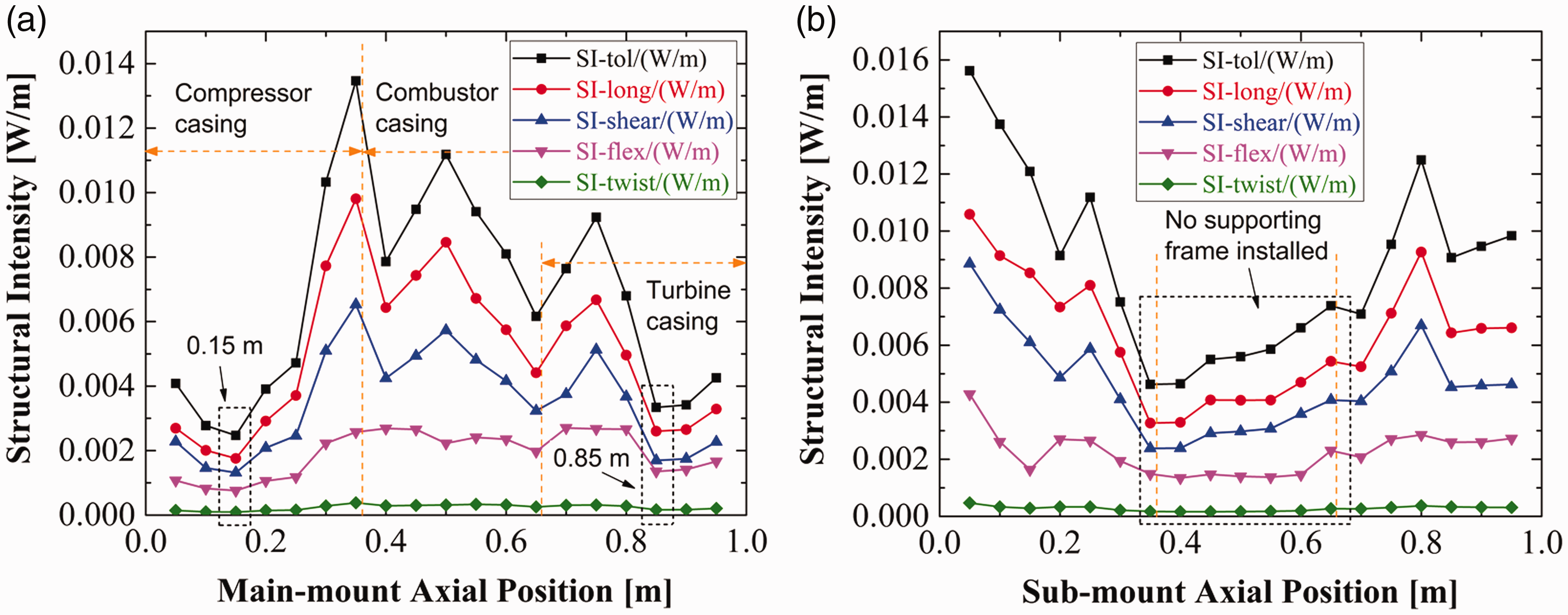
The average values of different SI components at different mount axial position: (a) changing M-M axial position and (b) changing S-M axial position. SI: structural intensity.
By comparing Figure 7(a) and (b), the variation trends of structural intensity have a wide disparity. It means that the M-M and the S-M have different influences on the structural intensity of the casing. However, for each line chart in Figure 7, the variation trends for different structural intensity components are totally same, which means that changing the axial positions of the mounts does not affect the proportion of each structural intensity component. Moreover, from Figure 7, it can be found that the longitudinal wave structural intensity has the highest proportion of all components, which means that the vibrational energy flow of the casing is dominated by the longitudinal energy wave. However, the twist energy wave has the least influence on the vibrational energy flow of the casing.
Since vibrational energy flow is carried and transmitted by elastic vibration waves, it is necessary to express the wave equations of longitudinal wave, shear wave, twist wave, and flexural wave to analyze the transmission characteristics of vibration energy carried by these vibration waves. These wave equations can be expressed as follows
32


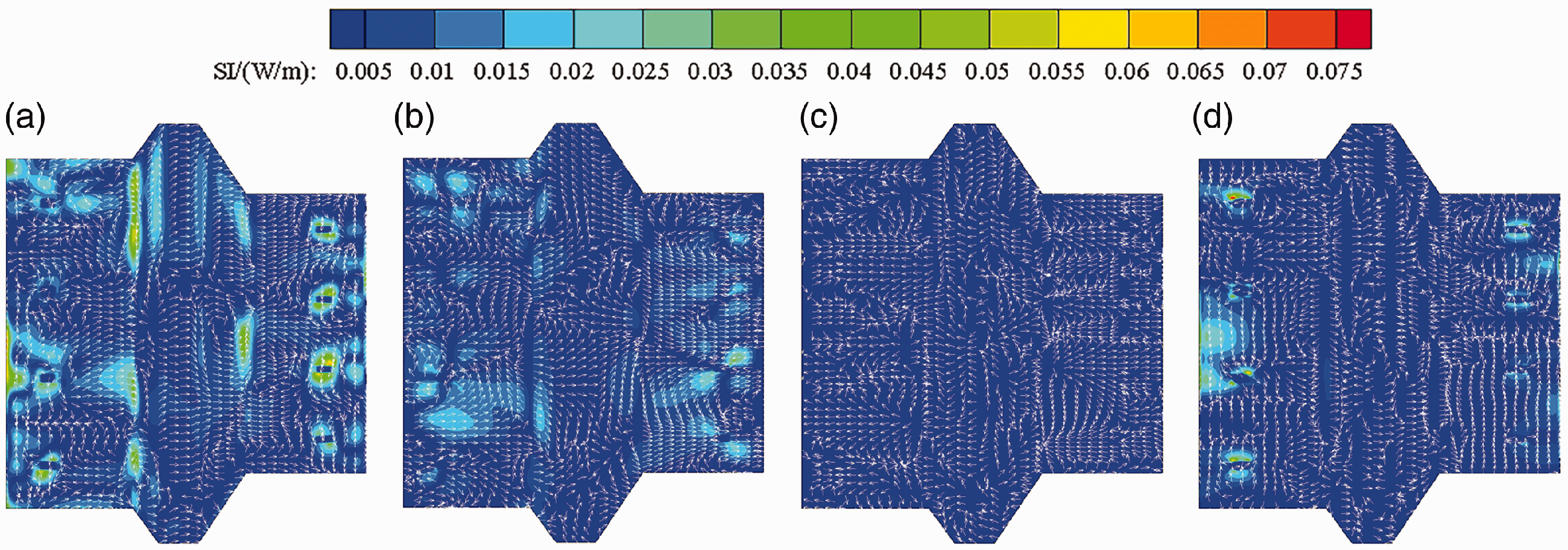
The scalar and vector diagrams of different components of the casing structural intensity field at the frequency of 466.67 Hz: (a) longitudinal wave structural intensity field, (b) shear wave structural intensity field, (c) twist wave structural intensity field, and (d) flexural wave structural intensity field.
For the casing excited by the single rotor, the torque of it can be ignored. Therefore, the vibrational energy flow carried by the twist wave is exceedingly small compared with that carried by other vibration waves, as shown in Figure 8(c). Most of the rotor unbalanced force transmitted through the support is converted into the membrane force and transverse shear force when it reaches the casing. Therefore, the longitudinal wave structural intensity and the flexural wave structural intensity are distributed around the joints between the casing and the supports of the casing. Especially, it can be found from Figure 8(d) that the vibrational energy flow carried by flexural wave has a limited distribution area, and almost of it only distributes around the joints, which results in a low average value of this structural intensity component on the casing. Therefore, the transmission of vibrational energy flow on the casing is mainly achieved by the longitudinal wave and the shear wave, which performs by the membrane forces. Especially for the longitudinal wave in which the direction of the particle displacements coincides with the direction of wave propagation, the distribution of this structural intensity component is almost consistent with that of the total structural intensity as shown in Figures 6(a) and 8(a). It means that this component has the greatest impact on the total structural intensity field of the casing, which is consistent with the results as shown in Figure 7.
Moreover, from Figure 7(a), it can also be seen obviously that the value of structural intensity of the casing touches the bottom when the M-Ms are set up at the axial position of 0.15 m and 0.85 m, respectively, and the interesting thing is that the supporting frames are exactly installed on the casing at these two axial positions. It reveals that the structural intensity of the casing drops sharply when the M-Ms are set up close to the position where the supporting frame is installed. However, the structural intensity of the casing is oscillating at a higher level when the M-Ms are set up on the combustor casing on which no supporting frame is set up. Overall, these findings indicate that the structural intensity of the casing will decrease when the M-Ms are set up at the positions that are close to the joints between the casing and supporting frame. On the contrary, from Figure 7(b), it can be found that value of structural intensity drops sharply when the S-M is set up close to the combustor casing flanges, and this value has a slight change when the S-M axial position changes along the combustor casing. By comparing Figure 7(a) and (b), it can be found that the variation trends of structural intensity are almost opposite in these two line charts, which means that the structural intensity of the casing will decrease when the S-M is set up on the casing that has no supporting frame installed on it.
In summary, these results indicate that there is a strong association between the mount axial position and the structural intensity of the casing. In order to attenuate the vibration of the casing, it is better to setup the M-M at the position that is close to the supporting frame and the S-M on the casing that has no supporting frame installed on it.
Verification in the frequency domain and the time domain
In the previous subsection, utilizing the structural intensity method, some measures to attenuate the vibration of the casing by changing the mount axial positions are obtained from the numerical results. In this subsection, these measures are applied to this coupling model to verify their effectiveness. Therefore, the axial positions of the M-Ms and the S-M are exchanged. In this new case, the M-Ms are set up at the axial position of 0.2 m which is close to that of the joints between the casing and the supporting frame 1, and the S-M is set up on the combustor casing that has no supporting frame installed on it. Moreover, the natural frequencies close to the rotor design rotating speed in the initial case and the new case are, respectively, 488 Hz and 485 Hz, which are extremely close, and the mode shapes of these two cases at these natural frequencies are the same as well. Therefore, the differences in the numerical results due to the change in natural frequencies can be negligible. The structural intensity field of the casing in this new case is calculated and visualized in the form of scalar and vector diagrams and streamline representation, as shown in Figure 9.
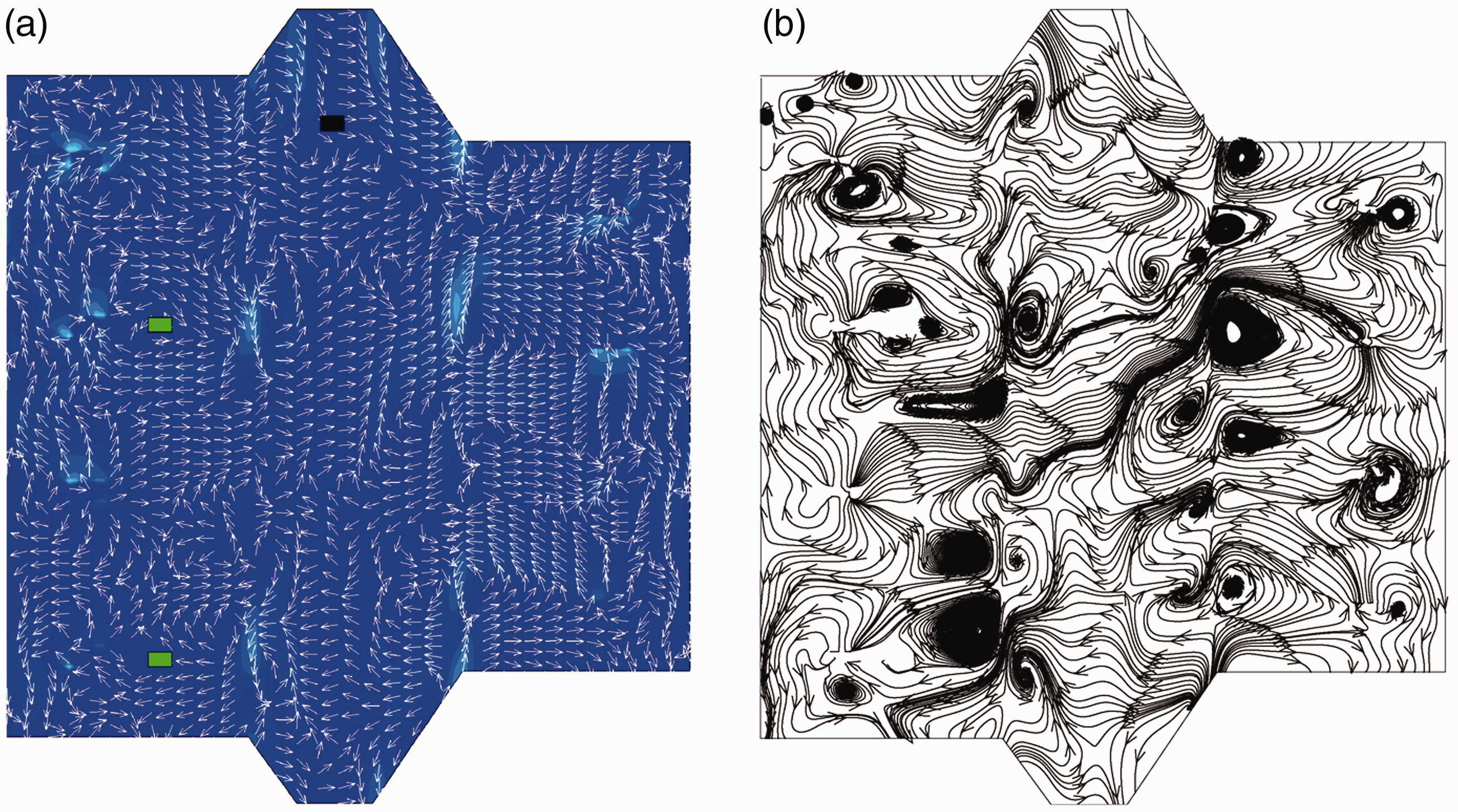
The structural intensity field of the casing at the frequency of 466.67 Hz in the new case: (a) scalar and vector diagrams and (b) streamline representation.
Comparing Figures 6(a) and 9(a), it can be seen obviously that the structural intensity of the casing significantly decreases in the new case, and the main flow of the vibration energy on the casing in this new case is less clear than that in the initial case, which means that the main transmission paths of the vibration energy are suppressed. In detail, from Figure 9(b), it is can be seen that most of the vibration energy transmitting from the joints between the compressor casing and the supporting frame 1 is reflected by the flanges between the compressor casing and the combustor casing. It makes this part of vibration energy cannot pass through the flanges and transmit to other casing parts. As a result, the vibration of the whole casing structure cannot be excited easily. Therefore, these measures are effective in the frequency domain.
However, the phenomena mentioned above are described in the frequency domain, which cannot dynamically analyze their causes from the perspective of time. Therefore, it is necessary to calculate and analyze the instantaneous structural intensity field of the casing in the time domain. In order to display more details of the vibration energy transmission processes of the casing, the instantaneous structural intensity field is calculated with a small enough time interval, which is set to 0.0001 s (less than one-twentieth of the rotor unbalanced force excitation period), and the numerical results of the initial case and the new case are visualized in the form of scalar and vector diagrams from 0.0001 s to 0.0006 s, as shown in Figures 10 and 11.
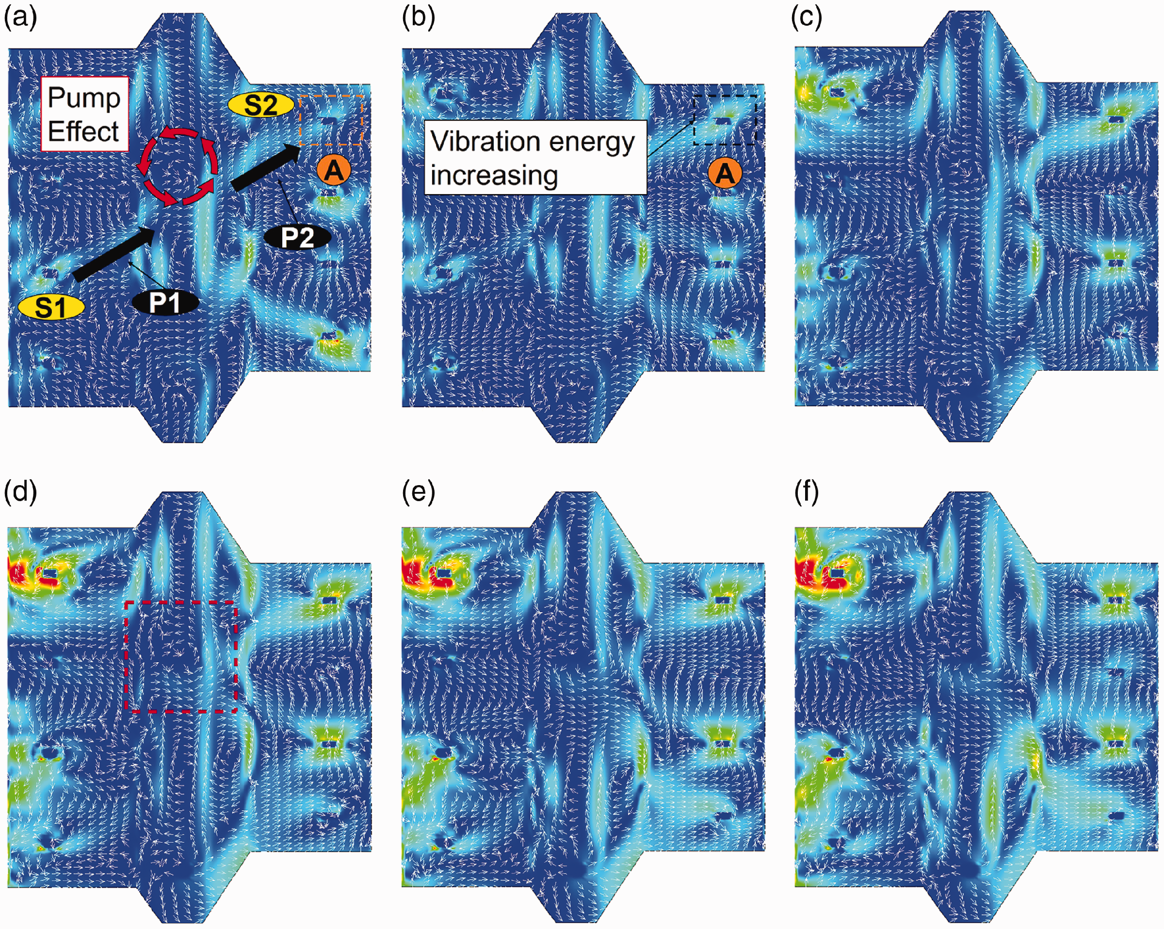
The instantaneous structural intensity fields for different time points at the design rotating speed in the initial case. (a) time=0.0001s, (b) time=0.0002s, (c) time=0.0003s, (d) time=0.0004s, (e) time=0.0005s, (f) time=0.0006s.
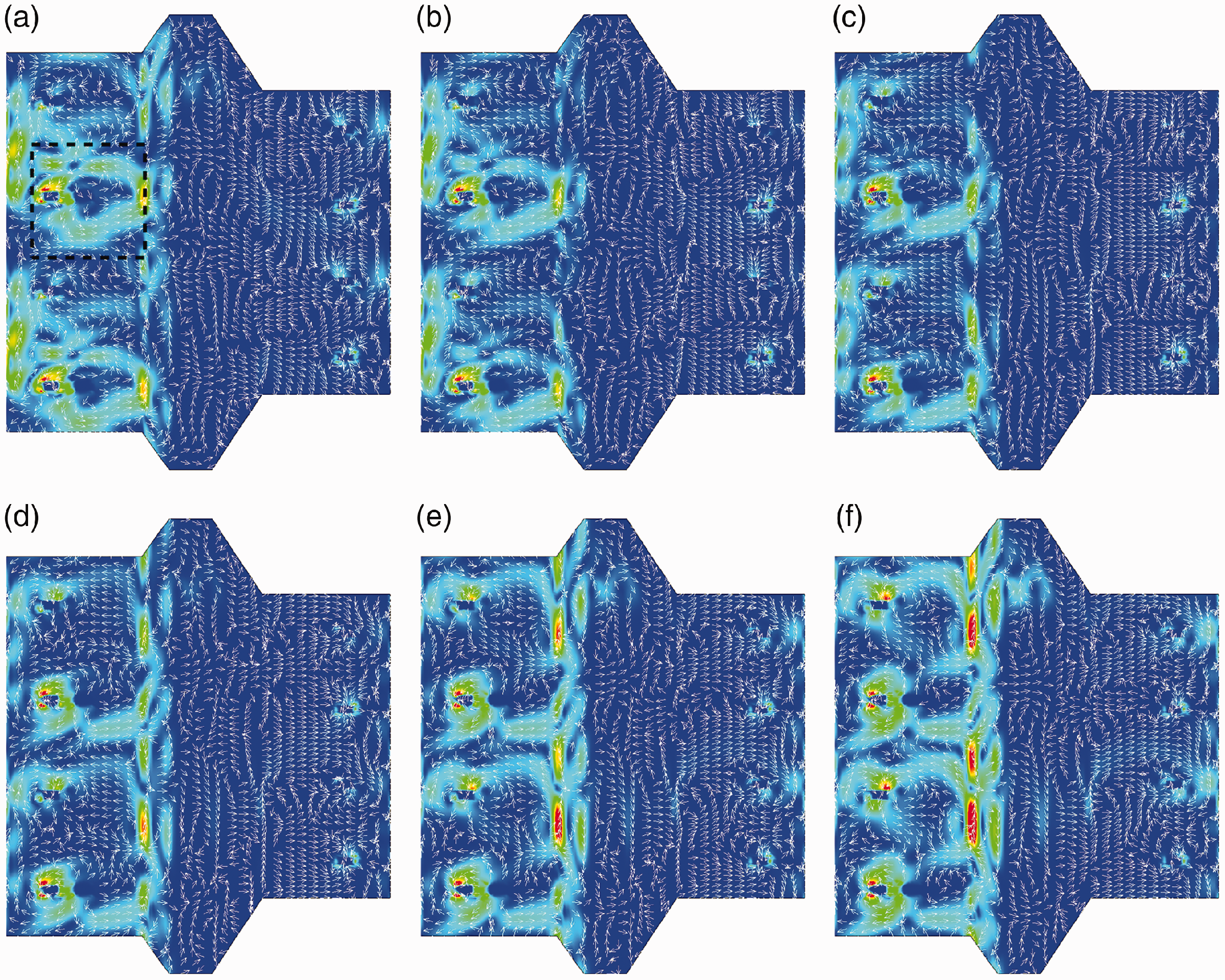
The instantaneous structural intensity fields for different time points at the design rotating speed in the new case. (a) time=0.0001s, (b) time=0.0002s, (c) time=0.0003s, (d) time=0.0004s, (e) time=0.0005s, (f) time=0.0006s.
By comparing the results at the same time point in these two figures, as expected, the instantaneous structural intensity fields of the casing are obviously attenuated in the new case, especially that of the combustor casing and the turbine casing. Moreover, another significant finding is that the vibrational energy flow transmits around the M-Ms, as shown in Figures 10(d) and 11(a). Taking the structural intensity field of the initial case at the time of 0.0004 s as example, the area in the red dashed box in Figure 10(d) is magnified, and its streamline representation is shown in Figure 12. It can be seen that the M-M induces an energy vortex field around it, as shown in the blue dashed box in this figure. The vibration energy streamlines are squeezed when they approach to this vortex field, which means that the relative spacing of the streamlines is reduced, as shown in the red dashed ellipse, and the intensity of the vibrational energy flow increases. Figuratively speaking, the M-M acts as a “pump” to enhance the vibration energy transmission capacity between the compressor casing and turbine casing when the M-Ms are set up on the combustor casing. As a result, the vibration energy of the compressor casing can transmit to the turbine casing easily. Specifically, in Figure 10(a), the vibration energy of the source
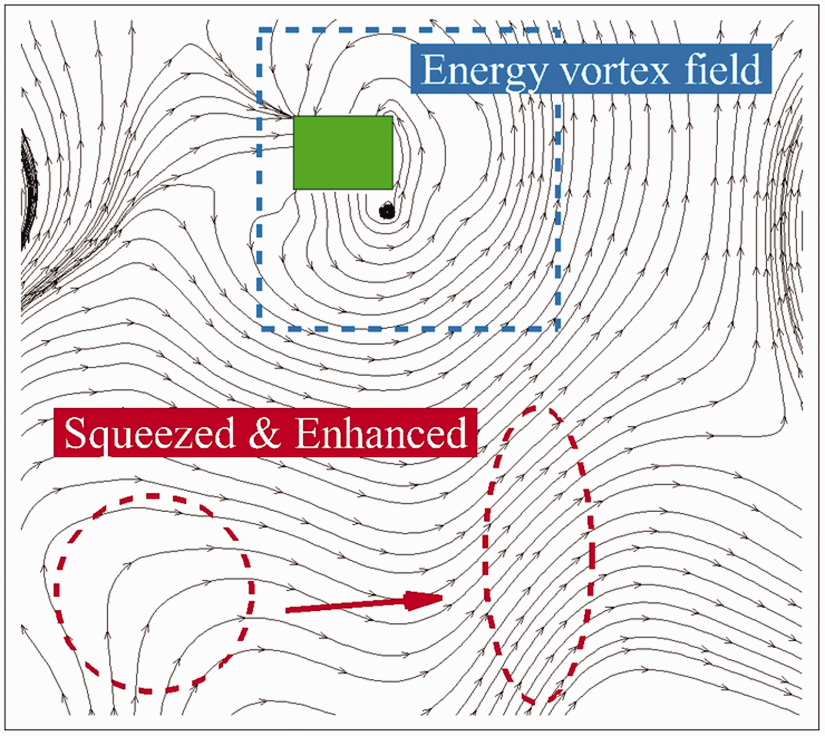
The streamline representation of the structural intensity field around the M-M in the initial case.
In Figure 11, because the M-Ms are set up on the compressor casing, nearly all of the vibration energy transmits on this casing. The area in the black dashed box in Figure 11(a) is magnified, and its streamline representation is shown in Figure 13. The transmission direction of the vibration energy is changed by the energy vortex induced by the M-M, and then most of the vibration energy is reflected by the casing flanges between the compressor casing and combustor casing. The intensity of the reflected vibrational energy flow is enhanced by this vortex field as well. Therefore, the vibration energy transmits back to the joints between the compressor casing and the supporting frame 1. As a result, only little of the vibration energy can pass through the flange to the combustor casing. The structural intensity is extremely low on the combustor casing and the turbine casing. The vibration energy transmission paths on the whole casing are effectively suppressed, and the vibration of the whole casing is effectively attenuated as well in the time domain.
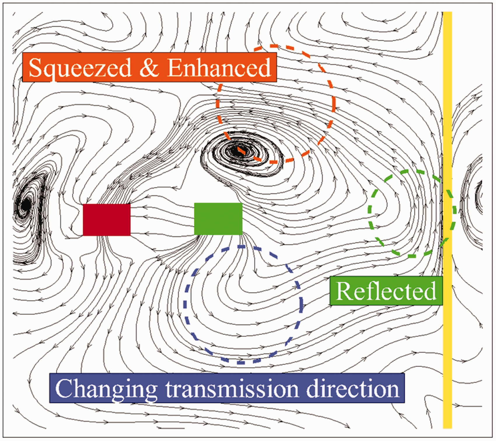
The streamline representation of the structural intensity field around the M-M in the new case.
Conclusions
In this paper, the effects of mount positions of aero-engine on the vibration energy transmission characteristics in casing structures are discussed, utilizing the structural intensity method. The goal of this study is to attenuate the vibration of whole casing caused by rotor unbalanced forces. A casing-support-rotor coupled model subjected to rotor unbalanced forces, therefore, is established by finite element method. The vibrational energy flow transmission characteristics of the casing with different axial positions of the M-M and the S-M are analyzed in the frequency domain. The structural intensity vector diagrams and streamline representations are used for indicating the sources, the sinks, and the paths of vibrational energy flow. It is found that the vibrational energy flow of the casing is dominated by the longitudinal energy wave, and the “pump effect” of the M-M enhances the transmission capacity of vibrational energy flow when the M-M is set up on the combustor casing, which induces the vibration of the whole casing. Generally, it is better to setup the M-M at the position that is close to the supporting frame and the S-M on the casing that has no supporting frame installed on it. Moreover, the effectiveness of these measures to attenuate the vibration of the casing is verified in the frequency domain and the time domain.
These findings contribute from the perspective of vibration energy to the understanding of the effects of mount positions on vibration energy transmission characteristics in aero-engine casing, and the present work is an attempt to present a systematic approach based on the structural intensity method to assist the aero-engine structure designer in controlling and solving the vibration problems of the casing and whole aero-engine.
Footnotes
Acknowledgements
The author(s) would like to thank the reviewers for their constructive comments.
Declaration of conflicting interests
The author(s) declared no potential conflicts of interest with respect to the research, authorship, and/or publication of this article.
Funding
The author(s) disclosed receipt of the following financial support for the research, authorship, and/or publication of this article: This work has been carried out with the supports of the National Key Technology Research and Development Program of China (2016YFB0901402) and the Key Project of National Natural Science Foundation of China (Grant Number 51736001).