
Abstract
Vibration control is a permanent and significant issue in all forms of structural dynamic analysis with the consistent objective being to minimize vibration levels. Considering that the propagation of vibration waves is essentially the transmission of vibrational energy flow (VEF), the fundamental requirement, therefore, is to minimize the VEF transmitted from sources to sinks and then to control and block the flow of vibration energy. Structural intensity (SI) method, combining forces with velocities to assess the magnitude and directions of VEF, is alternative to classical dynamic assessment methods offering insight into the transmission of VEF and studying additional phenomena which cannot be obtained by conventional dynamic analysis. In the field of noise, active noise control has been widely used in vehicles and headphones, which has achieved remarkable results by introducing a cancelling ‘anti-noise’ wave through an appropriate array of secondary sources. Analogically, it is considered whether the vibration of the structure can be attenuated by introducing a secondary reverse excitation (SRE) to offset the VEF transmitted in the structure. Therefore, this article combines the SI method and SRE to carry out related research on this issue. The rectangular plate with the circular hole subjected to the transient sinusoidal force, being widely used and found in various engineering branches, is taken as the research object. The developed simulation system consisting of the finite element tool and the in-house program is used to assess and visualize the instantaneous SI fields. The effects of the SRE acting on this structure on the transmission behaviours of VEF and the vibration suppression have been investigated in detail. Moreover, the transmission, conversion and balance relationships of the VEF have been derived from the general equation of motion and analysed as well. This study sheds new light on the vibration attenuation by introducing the secondary source from the perspective of VEF.
Keywords
Introduction
The attenuation of vibration level is a primary concern and a permanent issue in various engineering branches, such as vehicles, aircraft and aero-engines industries. There are two main groups of methods being usually considered for solving vibration control problems: passive control method (PCM) and active control method (ACM). 1 For passive and active vibration control, each one has its own advantages and disadvantages. The PCM is a simple approach which includes the use of dynamic vibration absorbers, barriers, viscous dampers, etc., to attenuate the interior vibration and noise.2-3 However, the resonance mechanism to absorb vibration on primary structure causing optimum solution to be valid only under a narrow frequency bandwidth or even a certain frequency and the requirement of the heavy damping materials limit the application of the PCM.4-6 Therefore, these limitations have prompted research into applying the ACM to attenuate the vibration and noise level. There are also two main groups of the ACM: active noise control (ANC) and active structural vibration control (ASVC).7-8 In most of the methods of the ANC, one or more control sources are used to introduce a secondary cancelling ‘anti-noise’ wave to suppress or attenuate the unwanted sound or noise originating from one or more primary sources such as ambient noise, which has been widely applied to the automobile industries,9-10 audio devices11-12 and so on. As for the methods of the ASVC, in addition to attenuating the structural vibration by introducing the secondary sources,13-14 the active magnetic bearings, 15 shape memory alloy 16 and other electronic devices 17 have also been used to attenuate the vibration, especially for the flexible rotors, by changing the structural inherent properties such as the stiffness and damping. In most of the approaches of the ASVC, the basic idea is either to suppress the motion at some discrete monitored points or change the inherent frequencies to avoid resonance. 18 However, there are too many degrees of freedoms of the mathematical models used in the control system; it is extremely difficult to attenuate the structural vibration globally and fundamentally utilizing the traditional ASVC which only takes the magnitudes of displacements, velocities and accelerations into consideration.
The propagation of vibration in the structure is essentially the transmission of the vibrational energy flow(VEF). The SI method,19-21 combining forces with velocities, assesses and predicts the magnitudes and directions of the VEF in the structure, which can be used to describe how the vibration energy in a vibrating structure transmits throughout the structure and to identify sources and sinks of the VEF by its divergence field. 22 The SI method is an alternative to classical dynamic assessment methods offering insight into energy propagation within the structural systems and studying additional phenomena. In the numerical procedure, Marcos et al. 23 have developed the energy flow calculation procedure consisting of MSC/Nastran and MATLAB to predict the vibro-acoustic behaviour within the vehicle development process. Cho et al. 24 have developed analysis system combining in-house code and commercial FE tools to carry out structural intensity analysis of stepped thickness rectangular plates. And many scholars have utilized this method to study the vibration energy transmission phenomena of various vibrating structures.25-28 Therefore, it is considered, from a more essential point of view, whether the vibration of the structure can be attenuated by introducing a SRE to offset the VEF transmitted in the structure, which takes all of degrees of freedoms of the forces and velocities into consideration in this approach named vibrational energy flow cancelling (VEFC).
In this article, the research about the VEFC has been carried out utilizing the SI method based on the finite element method. The rectangular plate with the circular hole subjected to the transient sinusoidal force, being widely used and found in various engineering branches, is taken as the research object in this study. A simulation system, consisting of the finite element tool and the in-house program, has been developed being used to assess and visualize the instantaneous SI fields for this kind of plate. To attenuate the vibration level, the SRE is introduced and subjected to this plate. The effects of the SRE on the transmission behaviours of VEF and the vibration suppression have been investigated in detail. Moreover, the transmission, conversion and balance relationships of the VEF have been derived from the general equation of motion and analysed for a plate segment as well.
Theoretical background
Structural intensity method
The vibration waves carry and transmit the vibration energy to different parts of the vibrating structure. In the 1970s, Noiseux
19
developed the SI method by transferring the theory of sound intensity in acoustics to the field of continuum mechanics. It is a powerful and advanced method to assess the VEF transmitted in structures by characterizing the magnitude and directions of vibration energy, which represents the VEF through an elastic medium per unit time and unit cross-sectional area. Its general expression combining the stresses with the particle velocities can be written as
29

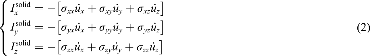
For solid elements, the SI indicates the VEF at a given infinitesimal volume. Each of the solid element surfaces includes a direct stress in accordance with the normal direction of this surface and two shear stresses perpendicular to the normal stress and orthogonal to each other, as shown in Figure 1. The instantaneous structure intensity expression of the solid element can be extended to the x, y and z directions in the Cartesian coordinate system, and it can be obtained by combining equation (2) Displacements and stresses for solid elements.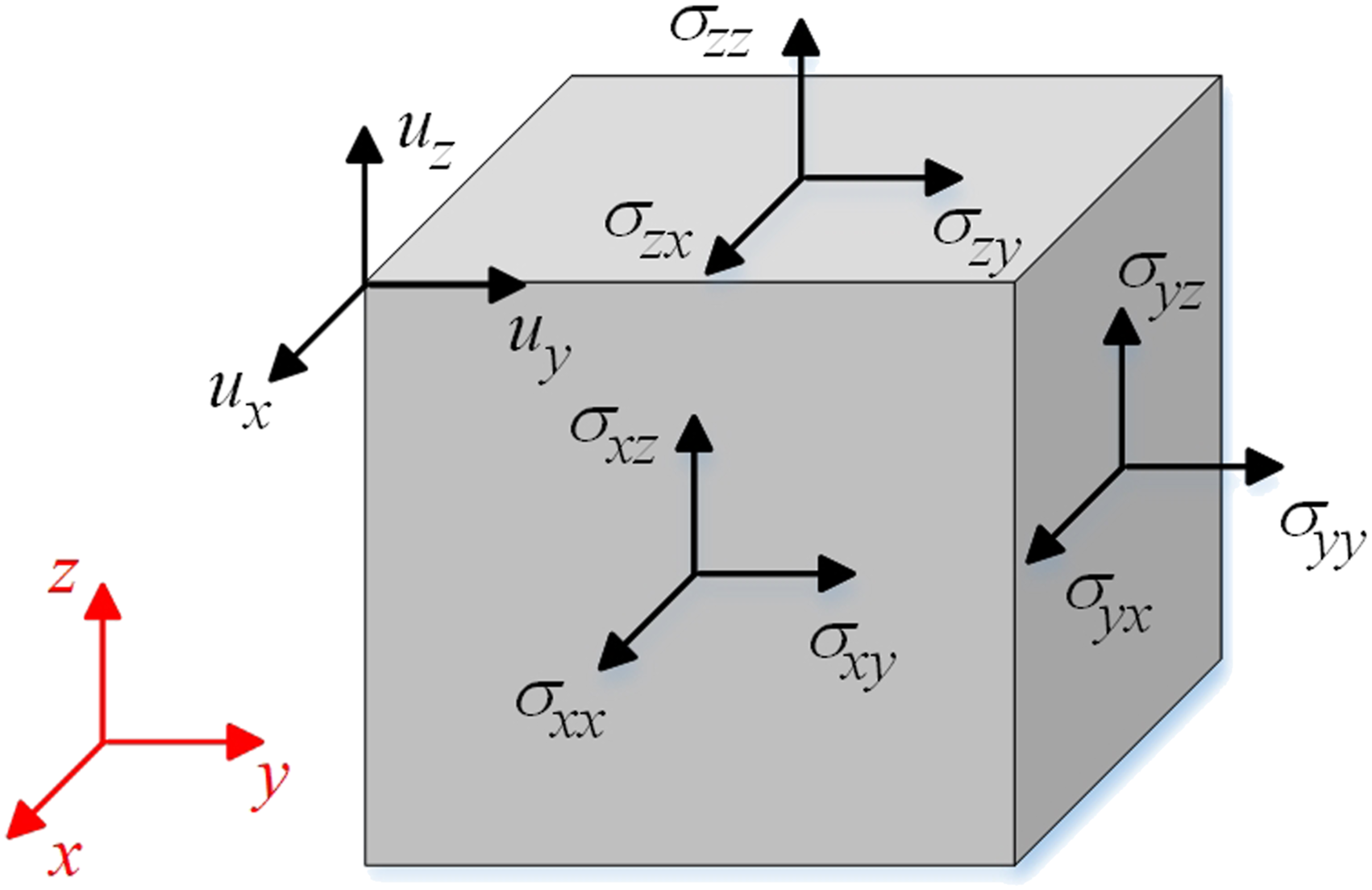
Streamline representation for structural intensity fields
The SI field of solid elements is a three-dimensional vector field. The streamline visualization technique is a powerful and useful tool to display the details of transmission or flow for a vector field. Generally, this technique is always applied to the flow field display for a velocity vector field. Analogous to the definition of streamlines in the velocity vector field, the tangential direction of each point of each VEF streamline is consistent with the direction of the SI vector at that point. Therefore, the streamline of the SI vector field can be expressed as
30

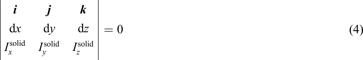
For the three-dimensional SI vector field of the solid elements, the differential equation describing the SI streamline is
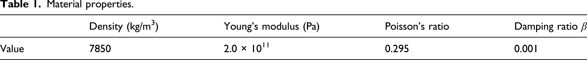
Modelling of the plate with a circular hole
Material properties.
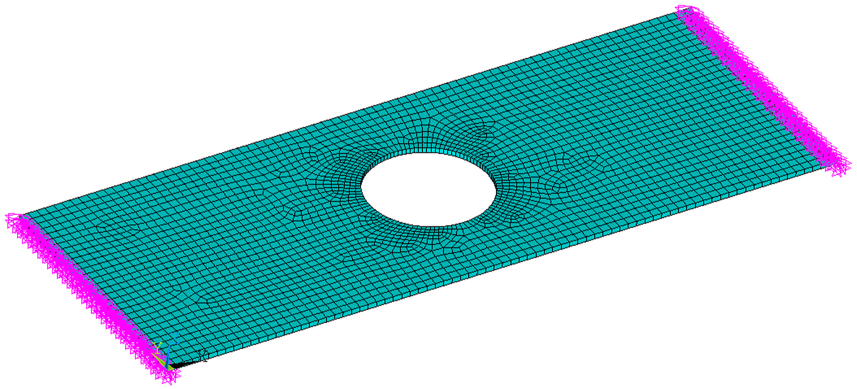
Finite element model of a simply supported plate with a circular hole.
Calculation of instantaneous structural intensity field
The SI field is a composite field composed of direct stresses, shear stresses, displacements and velocities. The existing finite element tools do not yet have the function of directly solving the SI field. Therefore, based on ANSYS Parametric Design Language (APDL), this article has carried out secondary development of finite element program coupling with the powerful matrix computing ability of MATLAB language (in-house program) and developed the simulation system of instantaneous SI to calculate and visualize the SI fields of this plate with a circular hole. The detailed calculation process of this simulation system is shown in Figure 3. The calculation flow chart of instantaneous SI field.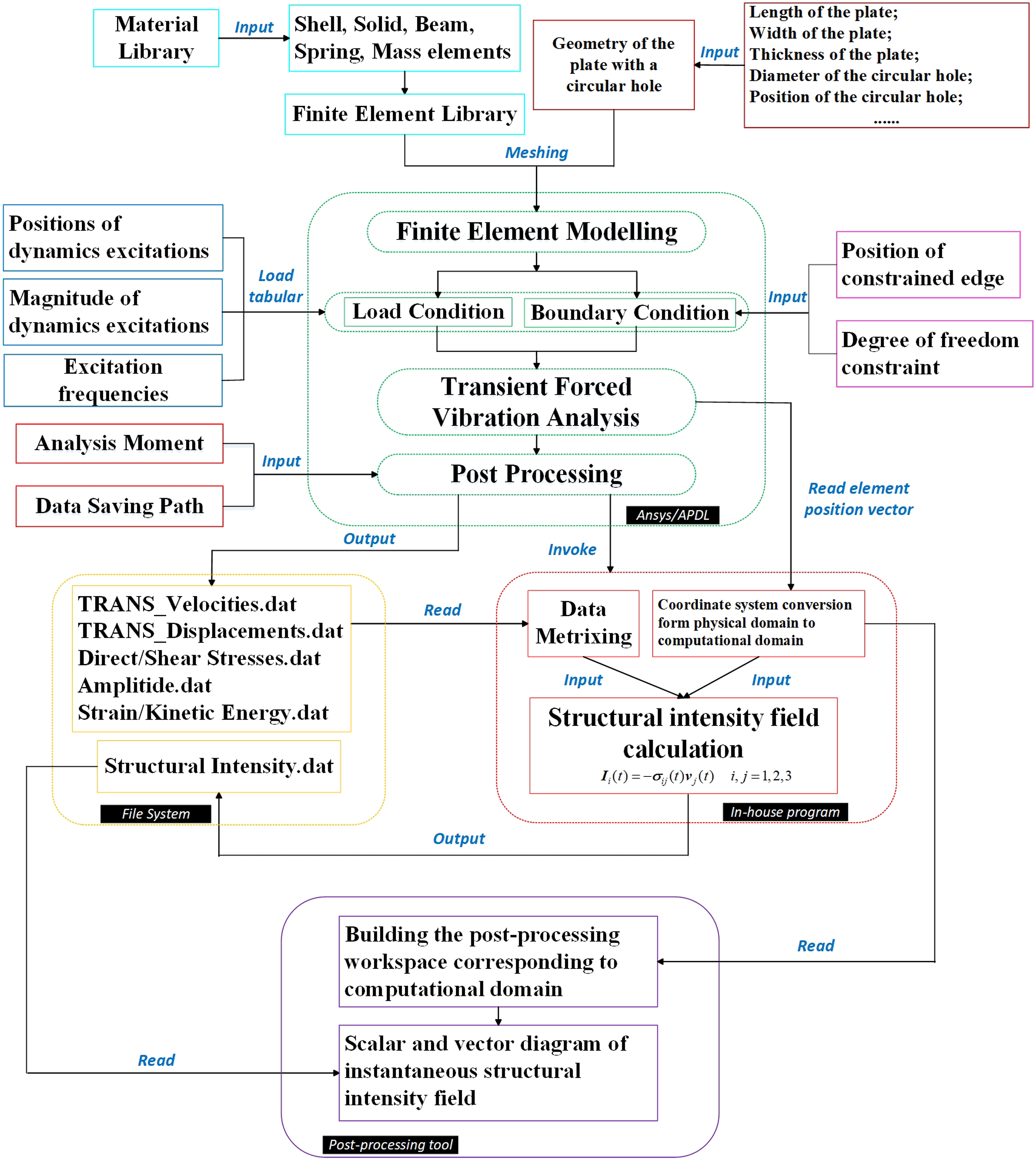
This simulation system controls the data interaction and message passing between these two parts. The structure parameters, material properties, load and boundary conditions are input into the simulation system for finite element modelling of this plate and carrying out the full-method transient forced vibration analysis. The computed results including translational and rotational displacements and velocities, direct stresses and shear stresses and strain and kinetic energy are output to the file system ready to be read. Next, the simulation system pauses the calculation of the finite element tool and starts calling the in-house program. When these data are read in by the in-house program, they are first matrixed for subsequent calculations. The conversed coordinate system and these matrixed data are used for the calculation of instantaneous SI fields. Finally, the computed results of SI are read by the post-processing tool to visualize the instantaneous SI fields based on equation (4).
To validate the accuracy of the SI fields computed by this simulation system, the SI fields of a simply supported thin aluminium plate subjected to a point excitation and an attached damper in Ref. 31 are used as a comparison. It is given in detail in Appendix 1.
Results and discussion
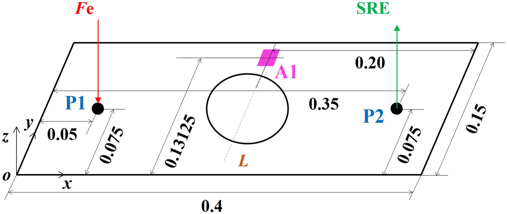
This section contains two subsections; the effects of the SRE on the transmission behaviours of VEF and the vibration suppression have been investigated in detail within 2 cases in Structural intensity fields with and without the SRE for Cases 1 and 2; the transmission, conversion and balance relationships of the VEF have been derived from the general equation of motion and analysed for a plate segment in The transmission, conversion and balance relationships of the VEF. Figure 4 shows the primary excitation Fe and the SRE in the time domain. The phase of the SRE is offset by 180° from Fe reversing the excitation direction. Figure 5 shows the load positions of these two excitations. Fe acts at the point P1 and the SRE acts at the point P2. These two load positions are symmetrical with the centreline L. All of the cases are subjected by the primary excitation Fe at the fundamental structural frequency (118.47 Hz), which acts as the vibration source. For Case 1, the plate is excited by Fe only. For Case 2, the plate is, simultaneously, excited by Fe and SRE to verify the effect of the SRE on the vibration suppression. The instantaneous SI fields for these two cases have been visualized by the SI streamlines in one vibration period. The SI visualization and analysis are as follows. The primary excitation Fe and the secondary reverse excitation in the time domain. The load positions of the excitations.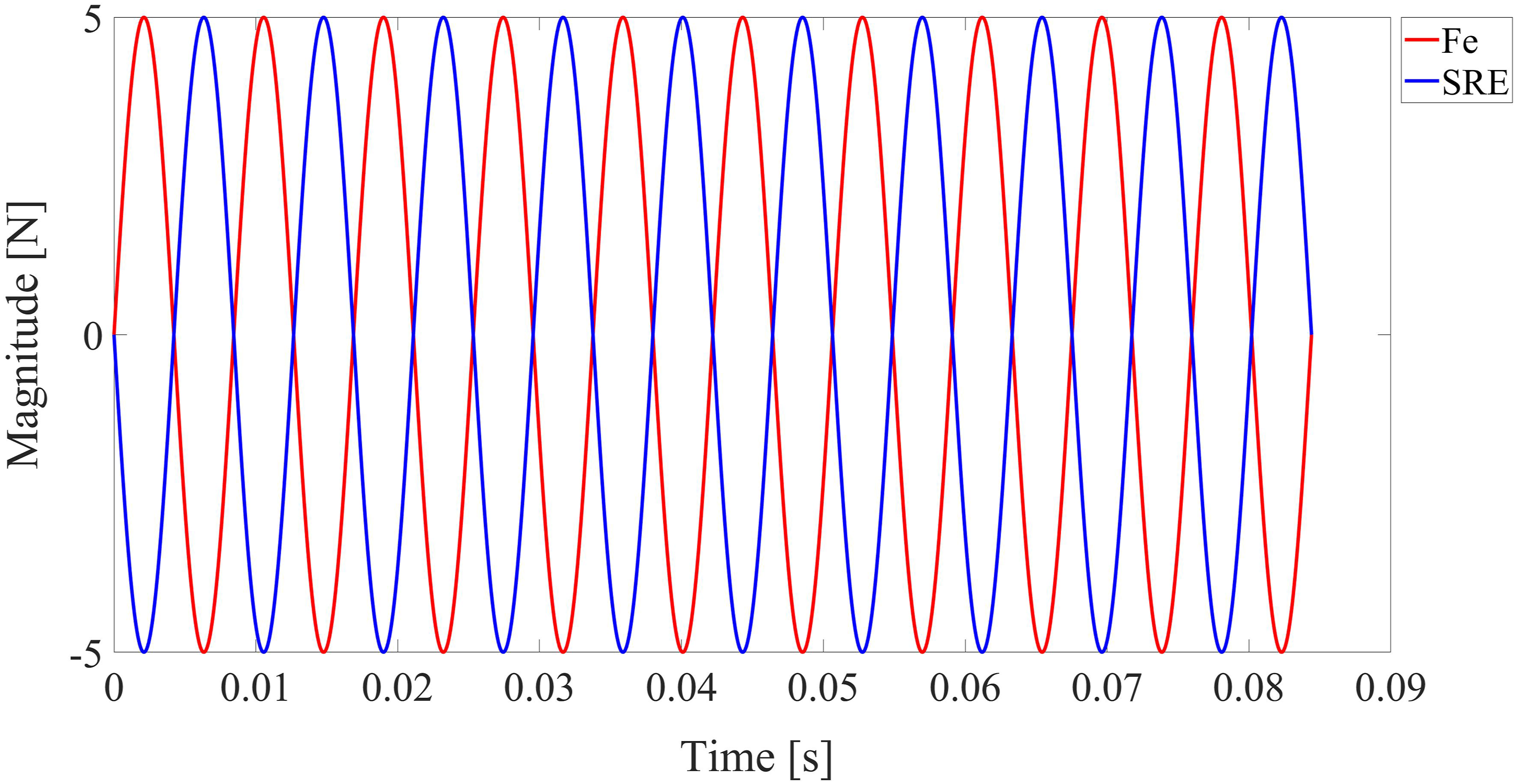
Structural intensity fields with and without the SRE for Cases 1 and 2
Figure 6 shows the SI fields of the plate with the circular hole due to the transient primary excitation Fe only. It can be clearly seen from the figure that the vibration energy flows out from the load point P1 and is transmitted on the plate. When the VEF reaches the edges of the long sides of the plate and the edge of the circular hole, the transmission direction changes to induce the vortex field of the VEF. Moreover, the edge of the circular hole retards the transmission of the VEF, causing its SI at the incident flow angle of 45° to increase, as shown in Figure 6(a). These positions are also the locations of the vortex fields of the VEF near the edge of the circular hole. In addition, it can also be found that the transmission patterns of the VEF at the moments of 1/6 T and 4/6 T, 2/6 T and 5/6 T and 3/6 T and T are identical, which means one vibration excitation period includes two VEF transmission periods, and the transient forced vibration calculation has been converged. Therefore, the instantaneous SI fields for Case 2 have been visualized only in half of the vibration period. The SI fields due to transient primary excitation Fe only. (a) 1/6 T, (b) 2/6 T, (c) 3/6 T, (d) 4/6 T, (e)5/6 T and (f) T.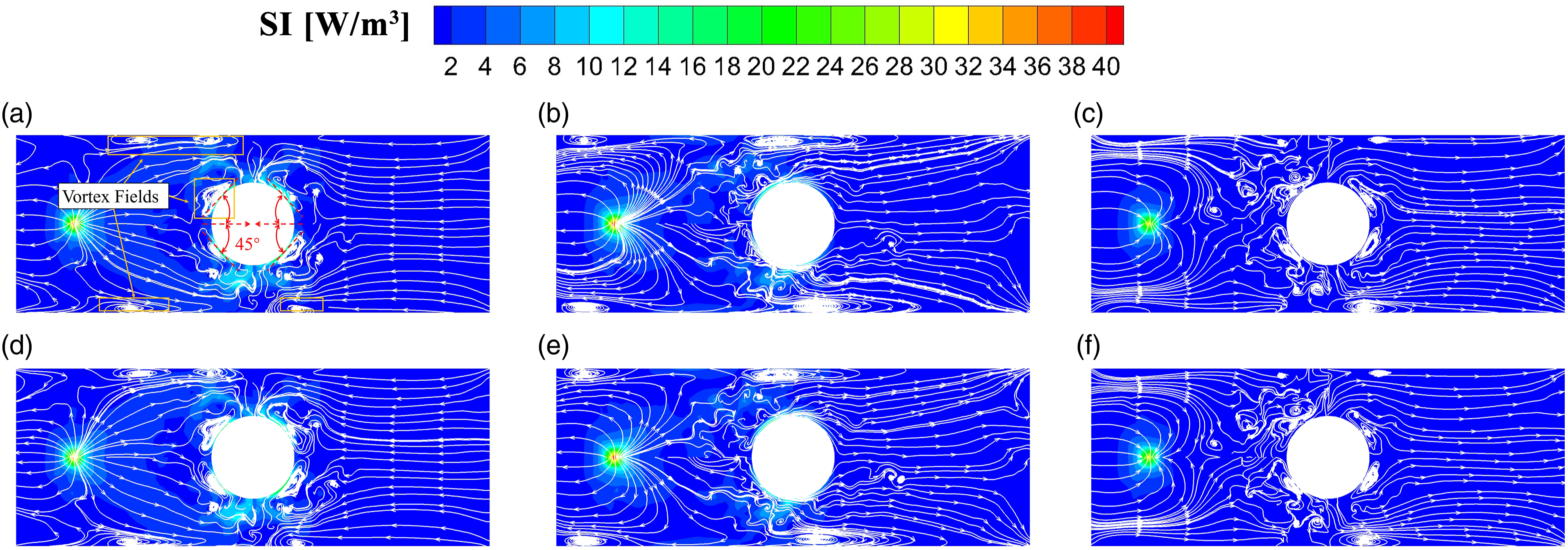
The SI fields shown in Figure 7 are the results of applying the SRE to the SI fields shown in Figure 6. Compared with the results shown in Figure 6, the magnitude of SI distributed near the edge of the circular hole is significantly decreased when the SRE acts on the plate. The high-value SI is mainly distributed near the load positions P1 and P2. Since the amplitudes of Fe and the SRE are equal and the load positions P1 and P2 are symmetrical about the centreline L, two streams of the VEF transmitted from these two excitation sources are converged near the centreline L or diverged from the centreline L, as shown in the red dotted boxes in Figure 7. The SI fields with the secondary reverse excitation. (a) 1/6 T, (b) 2/6 T and (c) 3/6 T.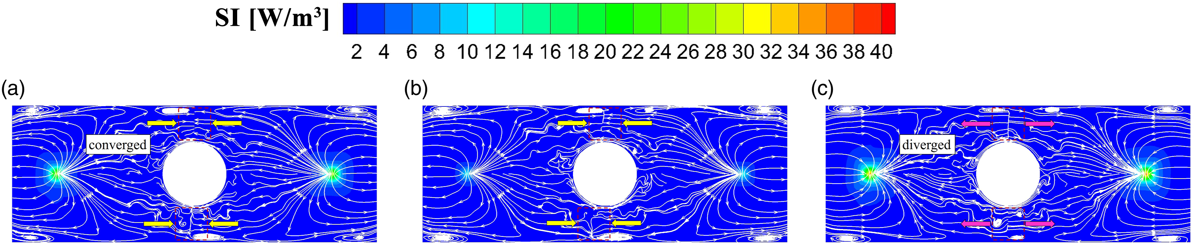
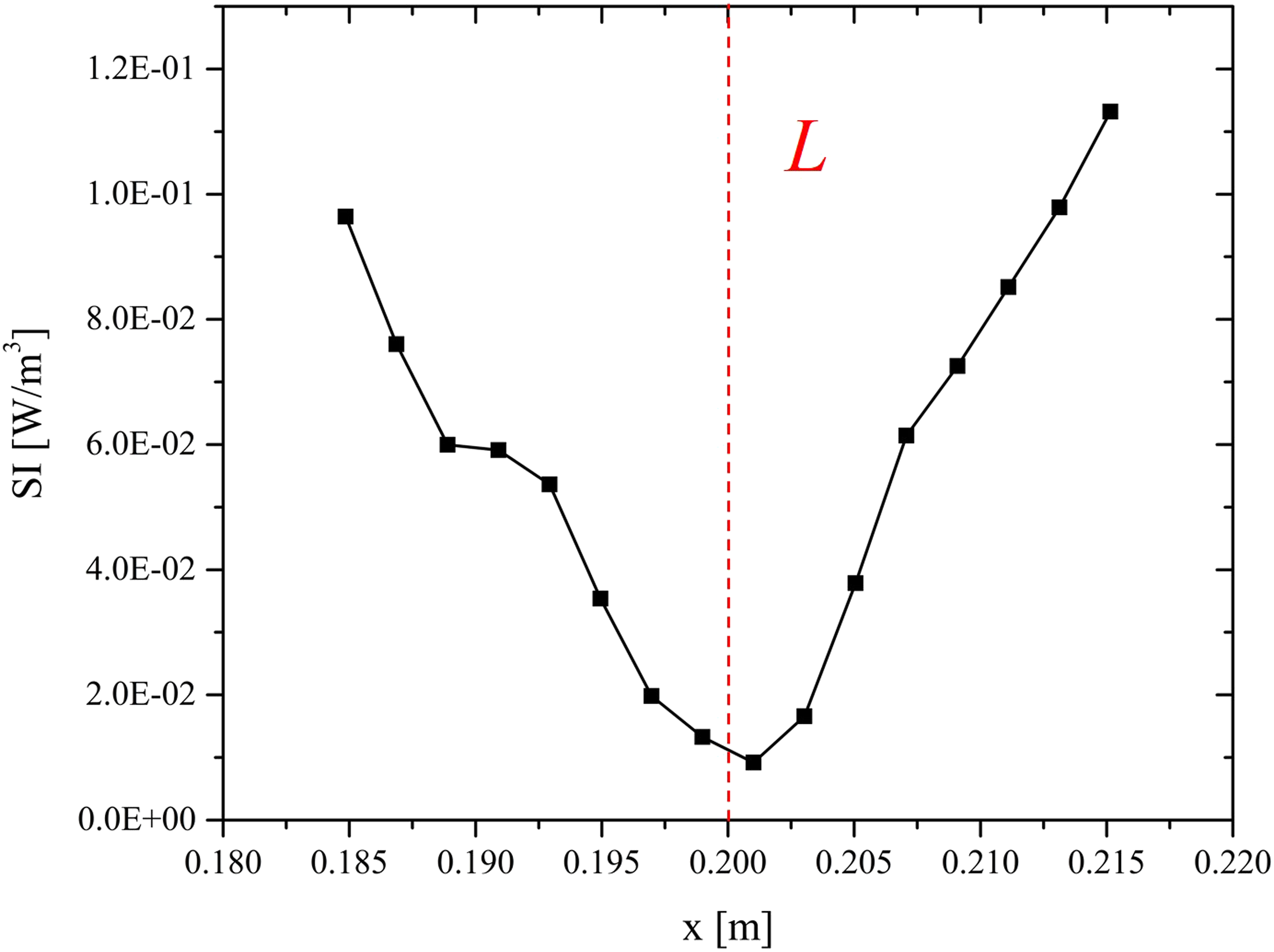
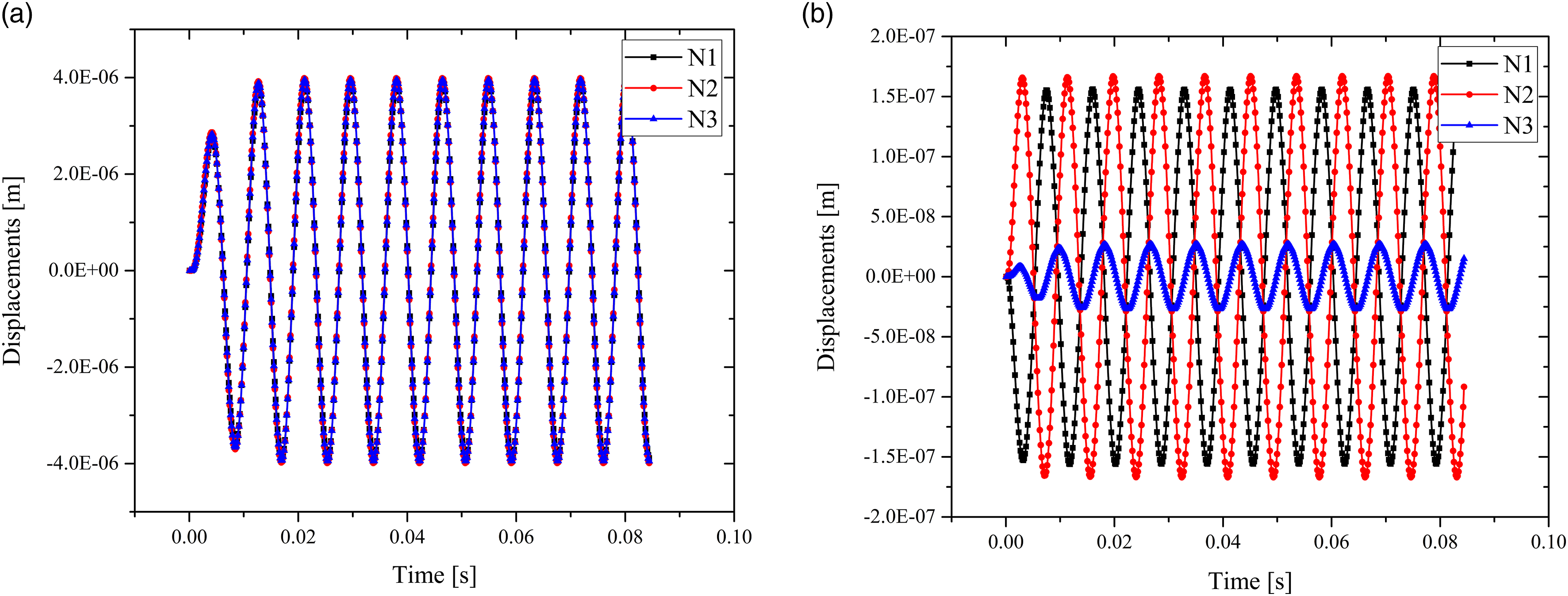
Compared with the results shown in these two figures above, it can be seen that the SI has been attenuated globally taken all of degrees of freedoms of the forces and velocities into consideration. According to the previous analysis, more attention should be paid to the SI distribution near the centreline L. Therefore, the values of the SI of sixteen monitored points M1 to M16 which are symmetrically distributed by L as shown in Figure 8 are extracted and plotted in Figure 9. It can be found that the strength of the VEF transmitted from P1 in the positive x direction and the strength of VEF transmitted from P2 in the negative x direction are significantly decreased as they approach L, respectively. Consequently, the magnitudes of all of the displacements, velocities and internal forces are decreased near the centreline L. To verify the correctness of this result, three monitored points are taken at the edge of the circular hole: N1 and N2 are symmetrically distributed with L and N3 is located on L, as shown in Figure 8. Under the excitation of the vertical forces, the plate vibrates mainly in the z direction. Therefore, the z-direction displacements of these three monitored points in Cases 1 and 2 are extracted, respectively, and plotted in Figure 10. For Case 1, these three points vibrate synchronously in the z direction with an amplitude of 4.0 × 10⁻¹⁶ m. For Case 2, the z-direction displacements of the points N1 and N2 are equal-amplitude and reversed. When these two symmetrically distributed, equal-amplitude and reversed vibrations are transmitted to the point N3, they cancel each other out, significantly attenuating the vibration amplitude at the point N3, as shown in Figure 10(b). Two streams of VEF carried by these two reversed vibration waves are transmitted towards the centreline L and converged near these positions cancelling each other out as well, as shown in Figure 7. The process is similar to that of the ANC. The next subsection will discuss the transmission, conversion and balance relationships of the VEF near the centreline L for further study. The monitored points for the SI and displacements. The distribution of the SI along the monitored points M1 to M16. The z-direction displacements for the monitored points N1, N2 and N3. (a) Case 1 and (b) Case 2.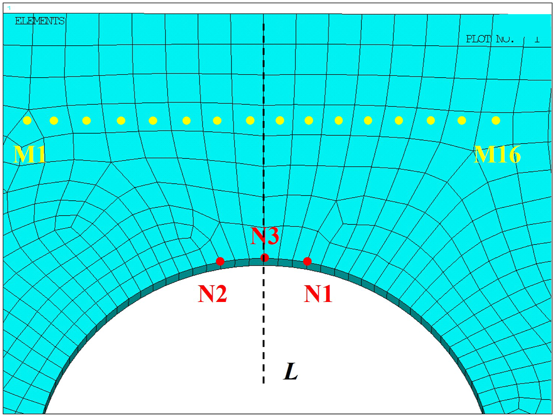
The transmission, conversion and balance relationships of the VEF
This subsection will start from the general equation of motion, considering the influence of the damping of the structure, to derive the energy balance relationship between structural vibration characteristic parameters and the VEF in the transmission and conversion processes.
The basic equation of motion in the stationary reference frame is of the following general form
Through a multiplication of velocity vector 

The first term on the left-hand side of equation (7) is the rate of change of the kinetic energy 
Now applying Gauss’s theorem to equation (8), we obtain
According to the definitions of the divergence and the SI, equation (9) can further be expressed as follows
The divergence of the SI denotes the characteristics of the sources and sinks of the VEF. A negative value of the divergence represents the energy sink absorbing the transmitted vibration energy and a positive value represents the energy source releasing the vibration energy to the surrounding structures.
And then equation (7) can be further expressed as follows
It can be deduced from equation (11) that for any research object, the volume integral of the divergence of the SI at any time on this object is equal to the negative of the sum of the rate of change of the total mechanical energy and the energy dissipated by the damping of the research object. From the point of view of energy conservation, it can be concluded that part of the VEF transmitted to the structure is used to change the kinetic energy and strain energy of the structure, and the other part is dissipated by the damping of the structure.
In order to study the transmission and conversion processes of the VEF near the centreline L, a 0.02 × 0.02 m square segment A1 is extracted from the plate, as shown in Figure 5. Ignoring the effects of the damping force, equation (11) is applied to this segment in Cases 1 and 2, respectively, and the results are shown in Figure 11. For Case 1, the segment A1 mainly absorbs the VEF transmitted from the source P1. Part of this absorbed vibration energy and the mechanical energy (strain energy and kinetic energy) of the A1 convert to each other near the centreline L to maintain in a significantly high level. For Case 2, although there is an additional vibration energy source P2, it can be seen from Figure 11(b) that the VEF absorbed by the A1 is very small due to the effect of the SRE, which is less than the magnitude of the change in the rate of change of the strain energy in Case 1. Most of the vertical vibration near the centreline L is cancelled out by the SRE as shown in Figure 10(b). Therefore, this absorbed vibration energy is hardly converted into the mechanical energy of the A1 for Case 2, which attenuates the vibration amplitude of this area effectively and essentially. The transmission and conversion processes of the vibrational energy flow of the segment A1 for Cases 1 and 2.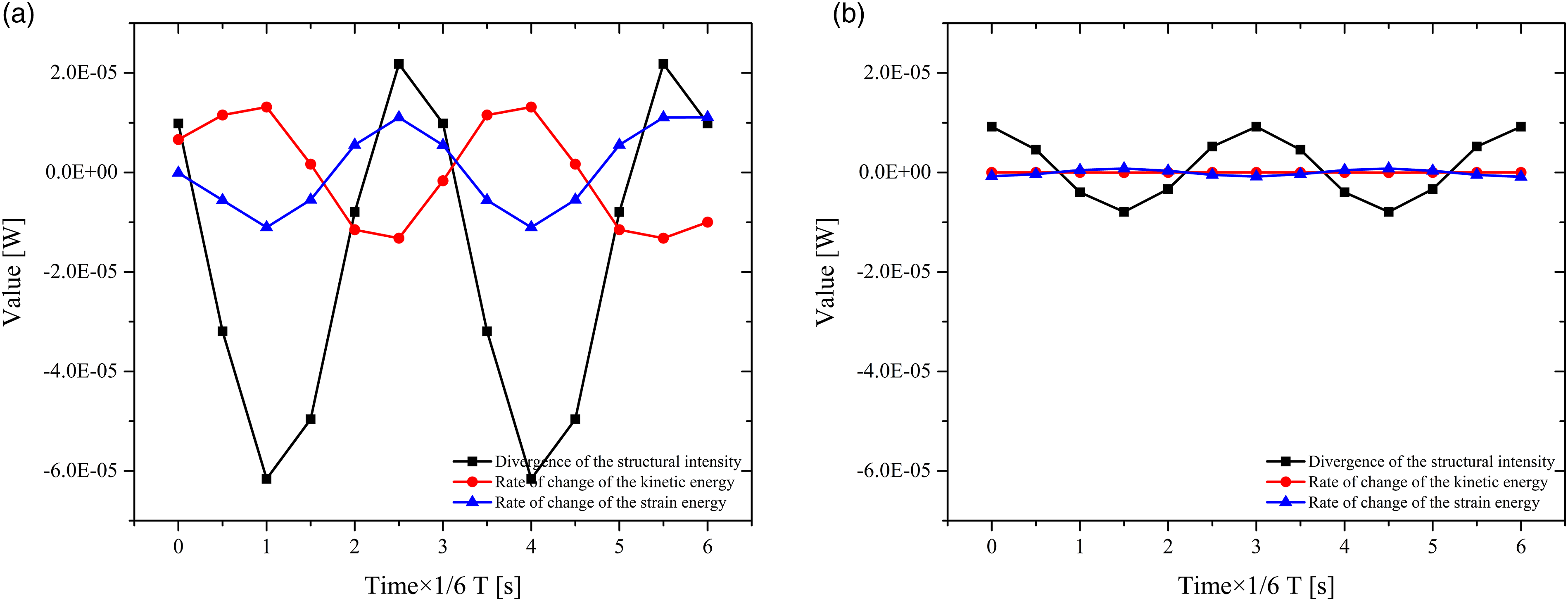
Conclusions
This article focuses on the issue called VEFC for a plate with the circular hole. The effects of the SRE on the transmission behaviours of VEF and the vibration suppression have been investigated based on the SI method and its visualization technology. A developed simulation system consisting of the finite element tool and the in-house program has been used to calculate the SI fields for two cases which are with and without the SRE, respectively. Two streams of VEF carried by two equal-amplitude and reversed vibration waves are transmitted, converged and cancel each other out significantly narrowing the distribution of the SI and attenuating the vibration amplitude. Moreover, the transmission, conversion and balance relationships of the VEF have been derived from the general equation of motion and further analysed. Effected by the SRE, the absorbed vibration energy is hardly converted into the mechanical energy, which attenuates the vibration amplitude effectively and essentially.
SI analysis is an alternative to classical dynamic assessment methods offering insight into energy propagation within the structural systems and studying additional phenomena. This study essentially analyses and explains the effects of the SRE on the vibration attenuation and sheds new light on the vibration attenuation by introducing the secondary source from the perspective of VEF.
Supplemental Material
sj-pdf-1-lfn-10.1177_14613484211024475 – Supplemental Material for Vibrational energy flow cancelling by loading a reverse excitation: Visualization and analysis
Supplemental Material, sj-pdf-1-lfn-10.1177_14613484211024475 for Vibrational energy flow cancelling by loading a reverse excitation: Visualization and analysis by Yingqun Ma, Qingjun Zhao, Wei Zhao, Long Hao and Binbin Liu in Journal of Low Frequency Noise, Vibration and Active Control
Footnotes
Declaration of conflicting interests
The author(s) declared no potential conflicts of interest with respect to the research, authorship and/or publication of this article.
Funding
The author(s) disclosed receipt of the following financial support for the research, authorship and/or publication of this article: This study has been supported by the National Key Technology Research and Development Program of China (2016YFB0901402) and the National Natural Science Foundation of China (51776198). The author(s) would like to thank them for funding it and their permission to publish the paper.
Supplementary Material
Supplementary material for this article is available online.
Accuracy validation of the simulation system
The simply-supported thin aluminium plate is 0.7 m long, 0.5 m wide and 3 mm thick. The plate is simply supported along the two long edges. The transient sinusoidal excitation force with an amplitude 1 N is applied at x = 0.1 m and y = 0.35 m on the plate. A viscous damper with a damping rate 2000 (N·s)/m is attached to the plate at x = 0.55 m and y = 0.15 m. The plate is assumed to be dissipationless, that is, without structural damping and material damping. The material properties are as follows: The Young’s modulus is 70 GPa, the Poisson ratio is 0.3 and the mass density is 2100 kg/m3. The geometry dimension and material properties of this model are consistent with those described in Ref. 31. The finite element model of this plate is modelled using 560 eight-noded isoparametric shell elements, which is consistent with that presented in ref. 31. Figure A1 and Figure A2 show the SI fields of this plate subjected to the excitation force of 14 Hz and 128 Hz, respectively. It can be found that the positions of the external force and the viscous damper and the main transmission paths of the VEF are extremely consistent, which verifies the accuracy and reliability of the results computed by the developed simulation system.
References
Supplementary Material
Please find the following supplemental material available below.
For Open Access articles published under a Creative Commons License, all supplemental material carries the same license as the article it is associated with.
For non-Open Access articles published, all supplemental material carries a non-exclusive license, and permission requests for re-use of supplemental material or any part of supplemental material shall be sent directly to the copyright owner as specified in the copyright notice associated with the article.