
Abstract
Traditional numerical control (NC) programming methods based on commercial computer-aided manufacturing systems usually require a large number of manual interactions with high-skilled experience, which not only results in low efficiency but also unstable machining quality. Especially since the structural complexity and machining requirements keep increasing, the NC programming is becoming a bottleneck problem in machining complex parts like aero-engine casings. This article proposes a feature-based automatic NC programming approach for aero-engine casings. A machining feature classification towards the geometric and machining characteristics of aero-engine casings is given. Then, a feature-based method to extract machining regions by considering the alternatives in selecting turning or milling operations is discussed. After the construction of machining operations, an undercut region detection method is also presented to evaluate the interim machining effects reasoned by each individual machining operation for excessive cutting avoidance. By implementing the proposed approach, a feature-based NC programming system is developed on a commercial computer-aided manufacturing platform and a real aero-engine casing is chosen to demonstrate the feasibility of the proposed approach.
Introduction
Aero-engine casings are the main loading-carrying structural parts of the aero-engine 1 whose machining accuracy and efficiency will directly affect the whole engine’s manufacturing quality and cycle. Since an aero-engine casing is usually with large size, complex structures, thin walls, high machining requirements as well as difficult-to-cut materials, its numerical control (NC) machining has become one of the most challenging manufacturing tasks in both research and industry.
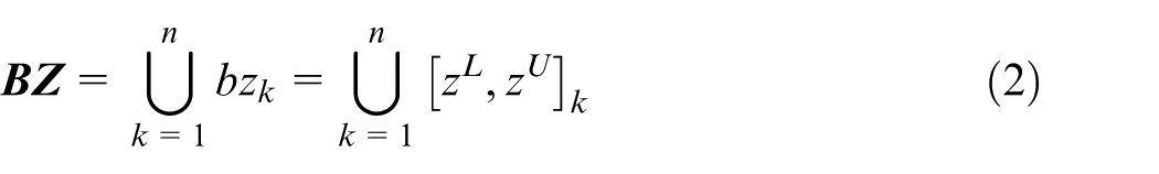
NC programming is to generate NC code for machine tool to drive the cutting movements. It is one of the most important procedures to determine the final machining result. Most existing NC programming methods are established based on commercial computer-aided manufacturing (CAM) systems like CATIA, NX and Cimatron. These systems provide abundant programming tools but for universal manufacturing industry; thus, the engineers have to plan every detail about how to machine the part by themselves. As a result, for complex parts like aero-engine casings, only high-skilled engineers can handle the task and a large number of manual interactions are usually essential. It further leads to long period and unstable machining results, which makes the NC programming a bottleneck problem in machining aero-engine casings.
Feature technology has been researched for computer-aided design (CAD)/CAM integrations for many years. 2 By associating machining knowledge to feature geometry, NC programming can be automatically carried out. Feature-based NC programming has been successfully realised in aircraft structural parts machining,3–5 but for aero-engine casings, there are still several deficiencies due to the complex structure and specific machining requirements. The first is feature classification. ISO 10303 AP224 6 provides a fundamental feature classification mainly for 2.5/3 axis machining, but in specific areas, feature categories usually need to be reclassified to represent complex geometry and machining knowledge. Second, since both turning and milling operations can be selected to machine a casing, there are usually alternatives in determining the machining regions for these two methods. Third, as aero-engine casings are mainly made up of high-temperature alloy or titanium alloy, excessive cutting must be avoided during the whole machining process for cutter and cutting safety. Thus, undercut evaluation should be seriously executed for every individual machining operation.
To overcome such problems, this article proposes a feature-based NC programming for aero-engine casings. Feature classification for aero-engine casings is first proposed to represent the complex part geometry together with typical machining knowledge, based on which, machining regions for each feature type are defined and extracted by comparing the advantages and disadvantages in both turning and milling. Then, an undercut region detection method is raised to evaluate the interim machining effects after each individual machining operation to prevent excessive cutting in its latter machining operations. A feature-based NC programming for aero-engine casings is then developed based on this research work and a real part is chosen from the industry as case study.
Related work
Feature classification and feature-based process planning are two core procedures of feature-based automatic NC programming. This section will review the related research work in these two aspects.
Feature classification
Feature classification is to find the essential feature types to represent the part models and machining knowledge in certain domains. ISO 10303 AP224 6 gives a number of fundamental machining feature types for 2.5/3 axis machining like hole, step, slot and so forth. But for parts with complex shape or structure, these feature types have to be extended or intersected with others. Miao et al. 7 proposed a machining features classification including inner profile feature, outer profile feature, through hole feature, blind hole feature and volume clear feature for CAD/CAM integration. Each feature type is distinguished by characteristics like basic condition, geometry and normal. Hoque et al. 8 established a detailed hierarchical feature library by adding feature types like keyway, edge round, rolled bar, box and so on. Further classifications will be made by considering semantics of design, machining and assembling. Venu and Komma 9 presented a two-phase STEP (Standard for the Exchange of Product Model Data)-based recognition method for features having non-planar surfaces which are not seriously considered in traditional feature categories. Li and colleagues10,11 presented a high-level machining feature classification made up of general pocket, hole, profile and rib for aircraft structural parts to strengthen the connection between feature geometry and manufacturing knowledge. In their further work,12,13 a multi-perspective dynamic feature is defined to facilitate freeform surfaces machining. Feature dynamics in the depth-of-cut, across the surface and in resources or manufacturing capabilities are defined in this feature concept to improve the accuracy, efficiency and timeliness of manufacturing planning and optimisation, especially for the integrated NC machining planning for complex freeform surfaces. Instead of considering geometry aspect, Sridharan and Shah 14 chose machining strategy as the reference to classify machining features into three feature types: Cut-Thru, Cut-Around and Cut-On.
Feature-based process planning
From the definition of a machining feature, feature geometry is usually associated with manufacturing knowledge in deciding cutting method, cutters, sequence and cutting parameters.15–17 Feature-based process planning could be regarded as the procedure to generate optimal sequenced machining operations based on these rules or reasoning logics converted from experiences and knowledge of human experts automatically. Each machining operation contains the geometry to be machined and the detailed machining information to generate the toolpaths. To overcome the inconsistent machining in pocket corners, Banerjee et al. 18 proposed a looping tool path strategy which is integrated to the process planning of pocket machining to improve cutting stability and efficiency. Recently, Sui et al. 19 presented a tool path strategy for the whole pocket feature by combining the strategies of corner-looping milling and clothoid curve transition to reduce the influence of the dynamic characteristics of the machine tool to surface quality. For the pocket feature, You et al. 20 discussed an optimisation-based cutter selection strategy to generate the cutter plan for the whole machining process by simplifying three-dimensional features into two-dimensional boundaries. In Liu et al.’s 21 work, a two-dimension (2D) configuration space-based approach was proposed to plan the cutters and machining allowances for the machining operations of complex pockets with multiple layers. Ji et al. 22 presented a two-step feature-based cutter selection algorithm. Cutters are first filtered according to workpiece materials and the geometry of machining features. The filtered cutters are then considered for all the machining features to calculate the machining costs in order to select the cheapest option. Sequencing of machining operations are usually converted to sequencing of machining features; Hao and Ma 23 put forward a hole sequencing method to minimise the number of cutter changes. Ji et al. 24 extended the sequencing objective to meet other specific machining requirements of machining feature types by introducing the concept of machining feature path graph, adjacency matrix and reachability matrix. Cutting parameters like cutting depth/width, feed speed and spindle speed are mainly chosen from the relevant machining templates by comparing the similarity between the feature to be machined and those saved in historic database.25,26 Besides the offline methods mentioned above, online process planning is getting more and more attention. Li and colleagues27,28 researched the threshold conditions of the cutting force, chatter and deformation during the machining of each feature type as well as the process plan adjusting strategies for each condition. With this work, the process plan can be adaptively optimised online with the real-time monitoring data.
Based on the above research progress, feature-based automatic NC programming becomes possible in machining complex parts like aircraft structural parts. However, since the specific characteristics in both geometry and machining, there are still several questions in achieving feature-based automatic NC programming for aero-engine casings. The first is any of the feature classifications mentioned above cannot fully cover the representation to neither geometry nor machining knowledge of aero-engine casings. The second is machining operations of aero-engine casings usually exist alternatives and the last is the detection of undercut region after each machining operation is limited. Therefore, in the section ‘Machining feature classification and extraction for aero-engine casings’ of this article, a feature classification for aero-engine casing machining is proposed as well as the method to recognise these feature types. Based on this feature classification, the ‘Machining region construction for machining features’ section discusses the approach to handle the alternatives in planning machining operations for each feature type and the ‘Undercut region classification and detection’ section gives the method to calculate the accurate region of undercut material left by each machining operation to avoid excessive cutting in latter machining operations. The ‘Case study’ section introduces the feature-based NC programming system developed based on the proposed approach and a case from the real industry will be used for case study. The final section provides the conclusion of this article.
Machining feature classification and extraction for aero-engine casings
Machining features are widely used as the information carrier of both geometry and cutting process to accumulate and reuse machining knowledge for automation and standardisation. However, the existing machining feature classifications, both the ISO 10303 AP224 and those provided by existing research work, failed to work in aero-engine casing machining. In this section, machining features to represent aero-engine casings will be defined and the extraction procedures will also be given.
Machining feature classification
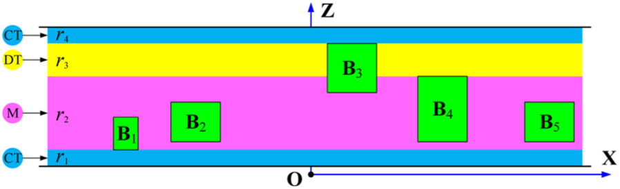
From the appearance point of view, an aero-engine casing looks like a rotative cavity and is divided into inner side and outer side, as shown in Figure 1. By considering both the geometry and machining process, four feature types are defined to represent an aero-engine casing in this article which are boss, hole, profile and pocket. Although the nomenclature of this feature definition seems nothing new, they may have different meanings.
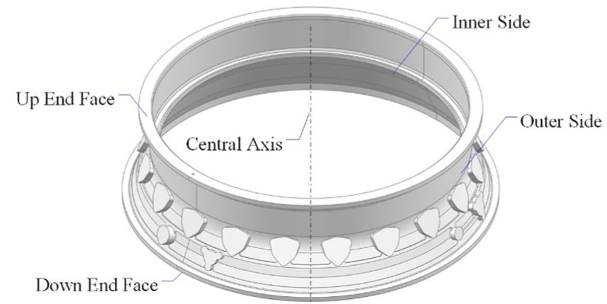
An aero-engine casing.
Boss
A boss is made up of a top face and its adjacent side faces, as shown in Figure 2(a). In most of the aero-engine casings, the top face is usually a plane and the side faces which all convexly connected to the top face are either planes or cylindrical surfaces. To represent the relationships among the feature geometric elements, attributed adjacency graph (AAG)
29
is used as shown in Figure 2(b). The nodes of an AAG refer to faces while the arcs represent the edges shared by adjacent faces. The attribute of the arcs is a Boolean variable to represent edge convexity and ‘1’ refers to convex connection while ‘0’ refers to concave connection. During feature recognition, the AAGs of the machining features could be easily constructed from the part’s B-reps. The face angles between the top face and the side face are always
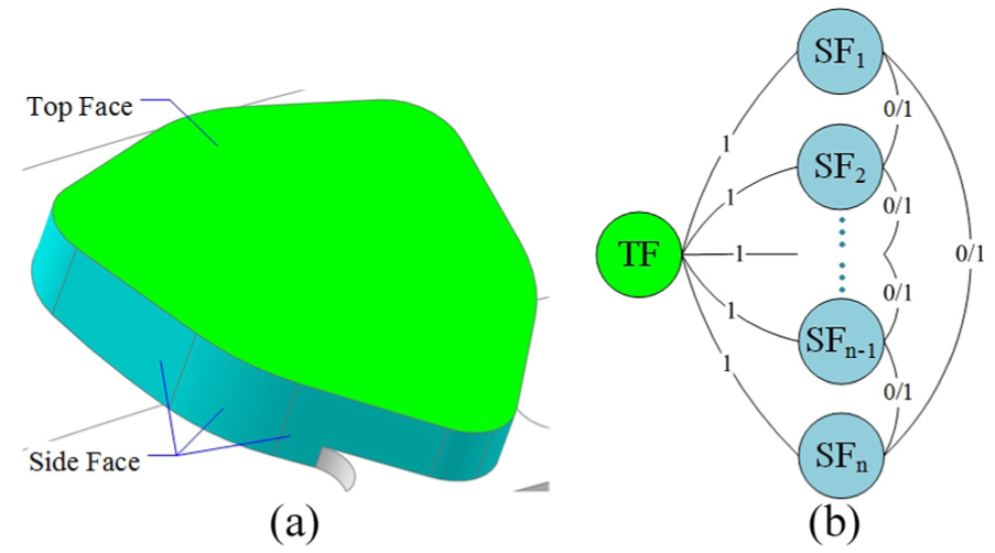
Machining feature type: Boss: (a) the geometry of a boss and (b) the AAG of a boss.
Hole
The definition of hole in this article is similar to that in most existing work as shown in Figure 3. In aero-engine casing, hole feature is usually intersected with the boss by sharing the top face. The hole faces define the shape of the hole and could be cylindrical surfaces, circular conical surfaces or their combinations. The bottom face refers to the last face in the axis direction and defines the hole depth with the top face. The machining process of hole features is mature and standardised; hence, we skip this to shorten the length of the article.
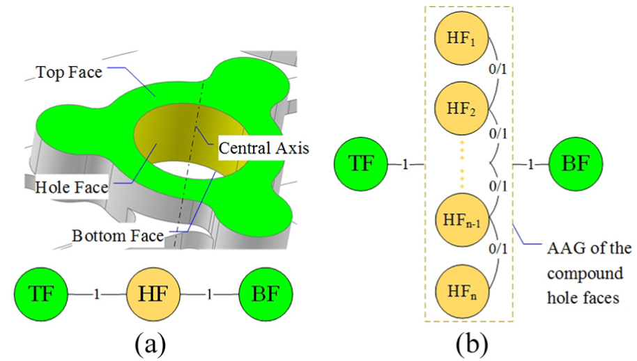
Machining feature type: Hole: (a) a basic hole feature and its AAG and (b) the AAG of a general hole feature.
Profile
A profile feature is constructed by the torus and end-to-end rotative surfaces with the same central axis of the part and has no intersections with the boss, as shown in Figure 4. Usually, most of the features inside the aero-engine casings are profile features. Turning will be chosen for profile features from roughing to finishing.
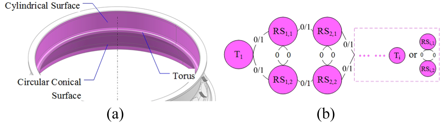
Machining feature type: Profile: (a) profile feature in the part and (b) the AAG of a general profile feature.
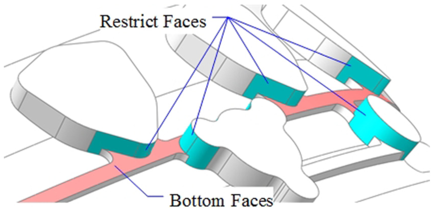
A pocket is composed of bottom face, side face and restrict face as shown in Figure 5. The connected rotative surfaces with the same central axis of the part that intersect with boss could be regarded as one bottom face with which a pocket could be found. The side faces of the boss that connect to the bottom face are defined as restrict faces since the cutter movement should avoid the collision to these surfaces during bottom face machining. The remaining concave surfaces connected to the bottom face, which may not exist, as shown in Figure 6, are named as the side faces of the pocket and once established, they need to be machined. Plunging can achieve a high efficiency in machining difficult-to-cut materials and thus is usually selected for pocket roughing. In pocket finishing, milling operations is the only choice for the side face while both milling and turning can be used for bottom face depending on its geometric characteristics.
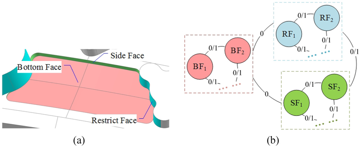
Machining feature type: Pocket: (a) a basic pocket feature in the part and (b) the AAG of a general pocket feature.
A pocket without side surfaces.
Feature recognition based on holistic attribute adjacency graph
The graph-based algorithm will be carried out to recognise the above-defined four feature types from the aero-engine casings automatically. By adding quantitative attributes such as face normal vector, face angle and edge length to traditional AAG, a holistic attribute adjacency graph (HAAG) was put forward which can represent freeform surface and more detailed relationships between adjacent surfaces.11,30 By converting the part model to HAAG, a uniform feature recognition algorithm was proposed for effectively extracting freeform surfaces, edge features, intersecting features and convex features. With this method, the three-dimension (3D) model of an aero-engine casing will be first represented as a HAAG. According to the AAGs of the four feature types defined in the section ‘Machining feature classification’, planes that are not perpendicular to the main axis direction are extracted as the seed faces of boss and holes while the surfaces revolving along the main axis are selected as the seed faces of profiles and pockets. The seed faces will be further applied as hints to execute hint search and extension to generate all features existing in the part. The feature result will be saved in a well-defined XML file.
Machining region construction for machining features
The machining of a part from roughing to finishing is realised by a series of sequenced machining operations. The prerequisite for generating machining operations is to decompose the material to be removed to different machining regions. Then each machining region will be assigned to one or more machining operations as the typical machining process requires. After extracting machining features from the aero-engine casing model, machining regions construction of the part could be converted to that of the machining features. A machining feature defines not only the feature geometry but also the typical machining process of this feature type including which face need to be machined and the corresponding machining strategy, cutting parameters, cutter parameters and so forth. As a result, most of the machining regions could be directly extracted from the machining features. For instance, the machining regions contained in a boss feature are the top face and the side face and that of a hole is its hole face. All surfaces of a profile feature define one machining region for turning. Particularly, for a pocket, each group of connected side faces could be regarded as a milling machining region. The pocket bottom face could also be machined by a milling operation, but for better machining result, a pocket bottom face may need to be divided into subregions for assigning milling and turning operations optimally.
To machine the pocket bottom face of aero-engine casings, turning is the first choice since better machining accuracy and surface quality could be achieved. Turning operations could be further classified into continuous turning and discontinuous turning. Obviously, continuous turning should be used as much as possible. However, due to the intersection with boss, most area of a pocket bottom face may not be suitable for continuous turning. In this condition, discontinuous turning operations could be selected since the boss distributed in the turning routes can be skipped over by setting cutter retracting and approaching during cutting. The disadvantage is that discontinuous turning will reduce the cutting stability and have to use specific cutters with strong impact resistance capacity. Moreover, since the part is fixed in the working table which will not stop rotating until the current machining operation is done, the cutter retracting and approaching during the discontinuous turning operation usually require a longer distance than the length of the boss to be skipped over in the circumferential direction. In other words, once there are more than one boss feature distributed in the turning route, if the distance between two neighbouring boss features along circumferential direction is not large enough, the restricted area could not be machined by discontinuous turning. The theoretical threshold distance could be calculated according to the spindle speed, radius of the circular turning route, cutter retracting and approaching strategy, position and dimensions of the boss and so on. In real machining, this theoretical threshold value will be enlarged with expert experience to ensure cutting safety. If neither continuous turning nor discontinuous turning could be used, the region has to be milled. The following context of this section will discuss a method to divide the pocket bottom face into milling regions and turning regions for better machining results.
A 2D local coordinate system is established to define the distribution of a boss that intersects with the bottom face as shown in Figure 7. The origin is the intersection of the down end face and the central axis. The Z axis coincides with the central axis and directs to the up end face while X axis is arbitrary in the vertical plane of Z axis. Thus, a boss could be uniquely defined as

where
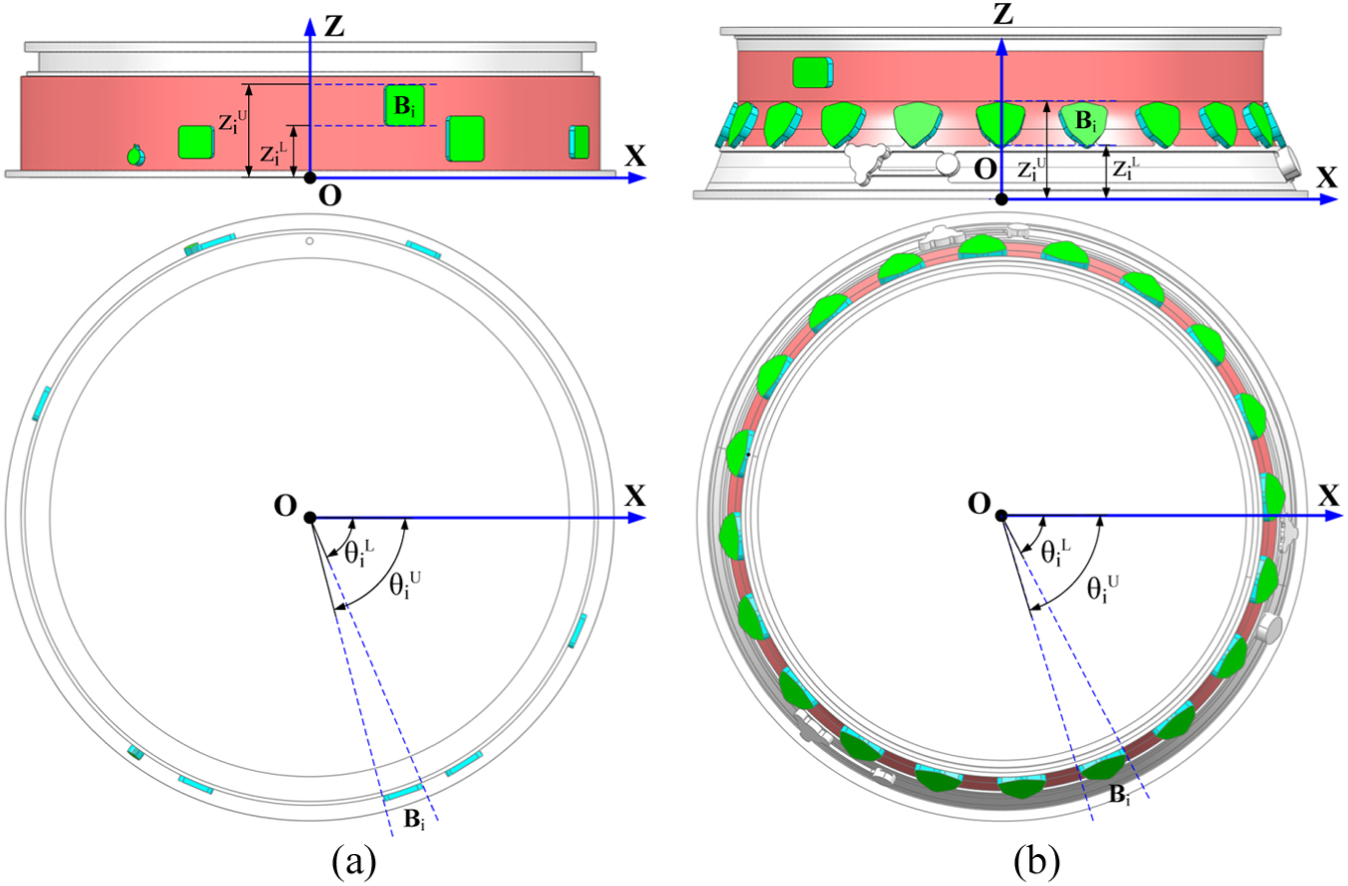
Position and boundary definition of the boss intersected with the pocket bottom face: (a) boss located on cylindrical surface and (b) boss located on circular conical surface.
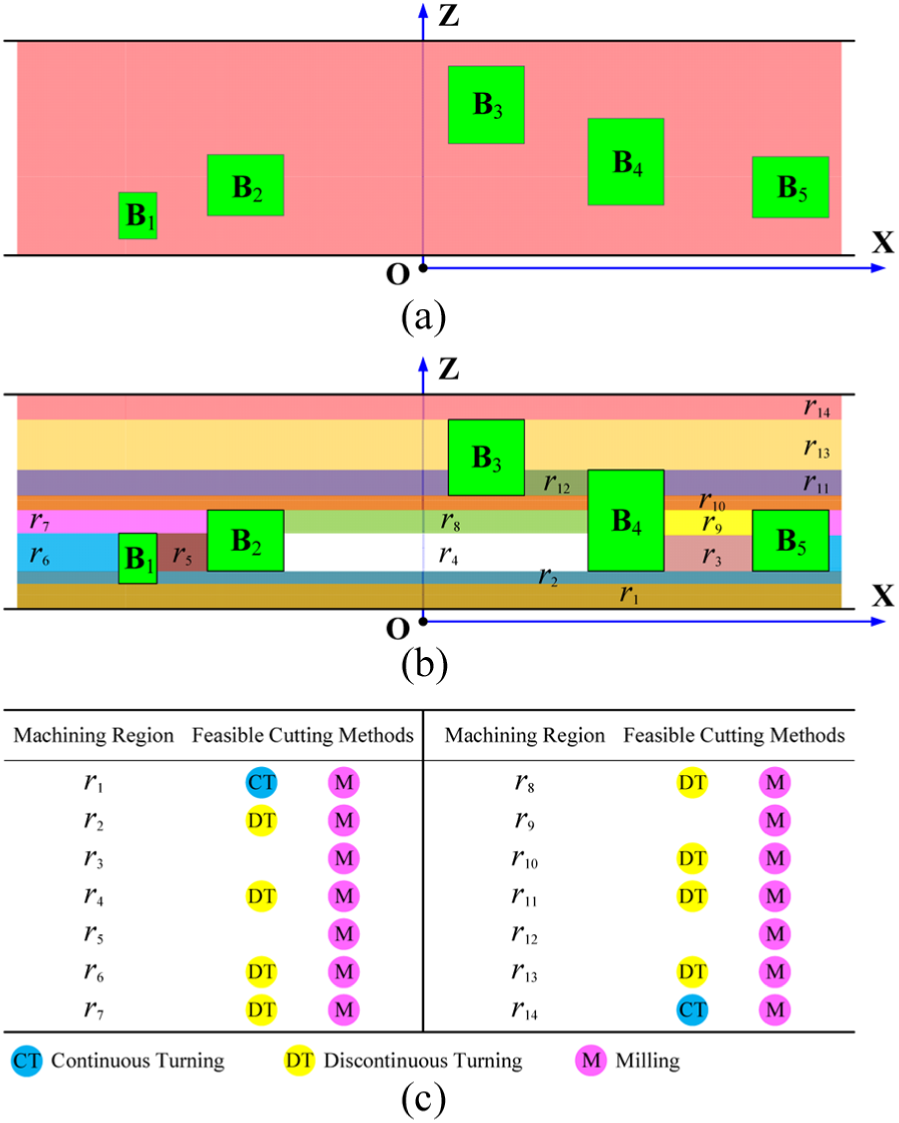
Surface subdivision based on the 2D distribution of the boss: (a) boss distribution on a rectangular plane, (b) surface subdivision along Z axis and (c) machining regions with different feasible machining methods.
The intervals in Z axis of all boss that are connected to the bottom face are represented as
where n is the number of the boss. Extract the lower and upper bounds,
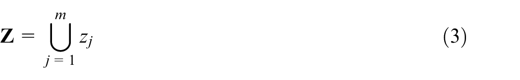
where m is the number of z values.
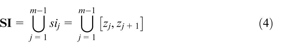
Each subinterval
For
A merging result for basic machining regions shown in Figure 8.
Undercut region classification and detection
After constructing machining regions of all machining features, a typical machining plan will be used to construct machining operations to each machining region. Cutters and machining allowances to machine certain feature type in typical machining plan are stationary, but the geometry of real feature instances usually varies considerably. As a result, there are usually a large number of undercut materials left during the machining process. The undercut material left by the former machining operations will change the cutting volumes of the latter machining operations as shown in Figure 10. This condition must be avoided in machining aero-engine casings of difficult-to-cut material like high-temperature nickel base alloy and titanium alloy. Therefore, a method to calculate the undercut regions for aero-engine casing machining will be given in this section. With this method, once a machining operation is planned, the undercut detection will be carried out.
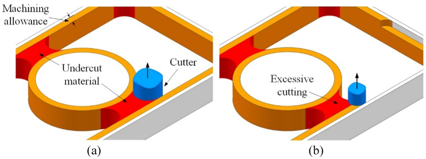
Excessive cutting caused by the undercut material left by the former operation: (a) undercut material and (b) excessive cutting of the latter operation.
In aero-engine casing machining, potential undercut regions are mainly constructed by the side faces or restrict faces of pocket and boss. These undercut conditions could be classified into three categories. The first class is caused by the side faces of a boss. The second is formed by the side faces of adjacent boss. The last is induced by the side faces and restrict faces in a pocket.
Undercut inside the boss
Extract the side faces of a boss from the feature recognition result and offset them outside with distance of (r + a) where r is the radius of the selected cutter and a is the machining allowance of the side face. Without loss of generality, henceforth a is set to zero to simplify the method description. If the offset faces of two nonadjacent faces intersect, there must be undercut as shown in Figure 11. The intersecting lines in this condition are parallel to the normal vector of the top face, as I1 and I2 shown in Figure 11(a). As a result, the calculation of undercut region is turned to a 2D question. Draw a circle with the cutter radius at the intersection position defined by the intersection lines. The undercut region is defined by the circle and the outer boundary of the top face as shown in Figure 11(b).
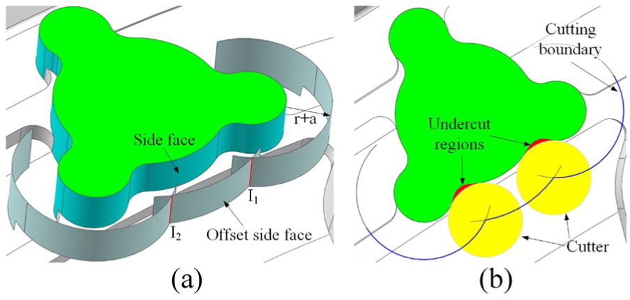
Undercut regions of an individual boss: (a) intersections of offset side face and (b) undercut regions.
Undercut between adjacent boss
The boss features will be first sequenced in circumferential direction according to the angles to X axis as shown in Figure 12. For the boss
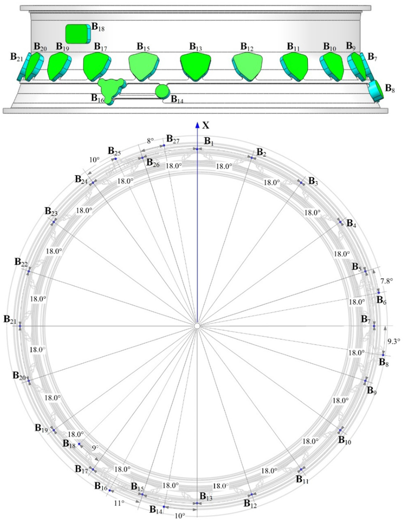
Boss features distribution in an aero-engine casing.
For each {
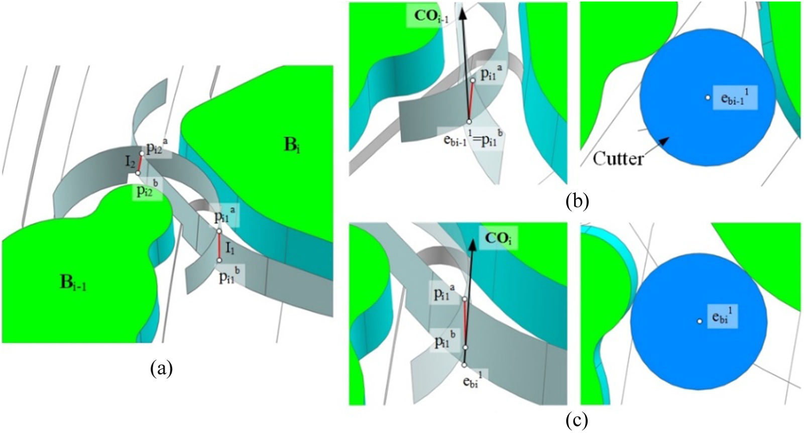
Boundary points to machine adjacent boss: (a) intersections of offset side effect, (b) endpoint to machine boss
The tangent lines when cutter reaches at the boundary point could be obtained as
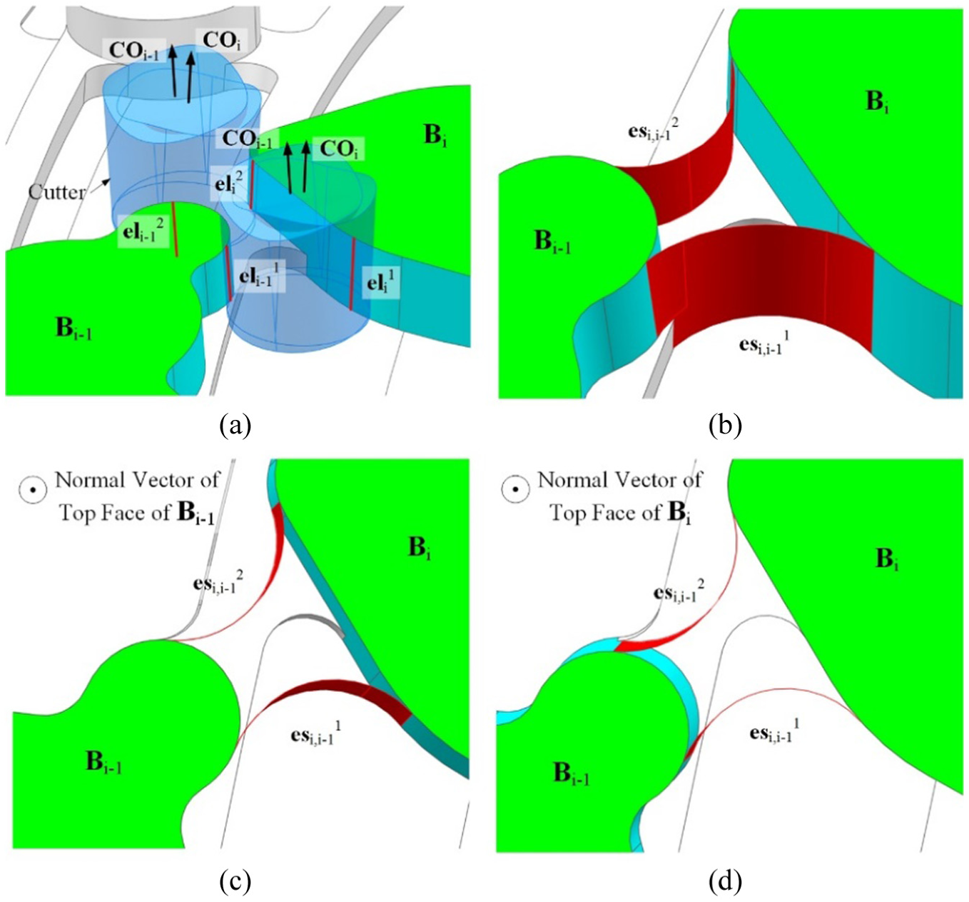
Undercut region between adjacent boss: (a) end lines on side faces of
Undercut inside the pocket
The procedure to generate the undercut regions in a pocket is similar to that between adjacent bosses. First get the intersecting line of the offset side faces and offset restrict faces. Then calculate the outmost part of the cutter profiles at the intersecting line with the method mentioned above. The difference is the cutter orientation when machining the side faces is variable. To get the cutter orientations at the boundary points, the cutter orientations of the boss which share the restrict faces as their side faces are extracted. Then linear interpolation could be used to calculate any cutter orientation at the offset side face.
Case study
Based on the above research work, a feature-based NC programming system for aero-engine casings is developed on the CAM platform of Siemens NX 7.5. The system contains two main modules: feature recognition and machining operation planning as shown in Figure 15.
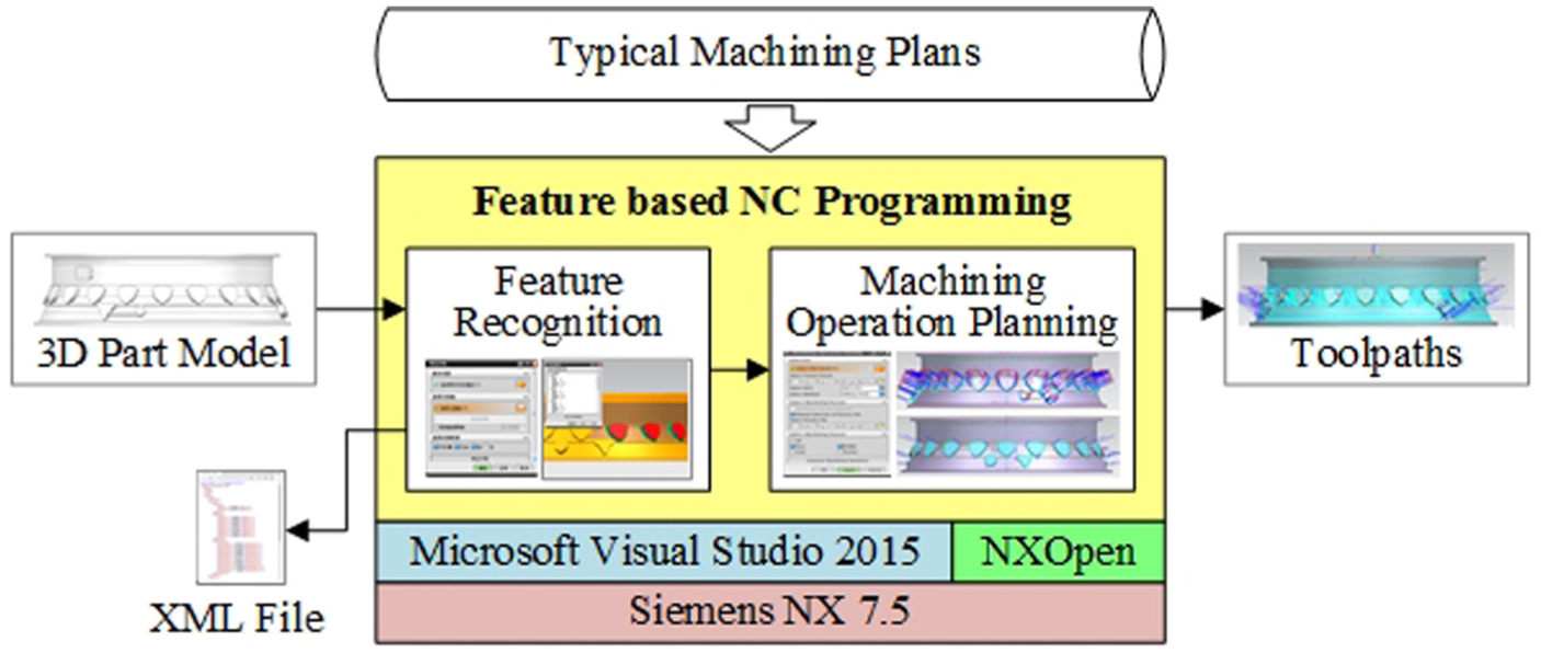
Structure of the developed NC programming system.
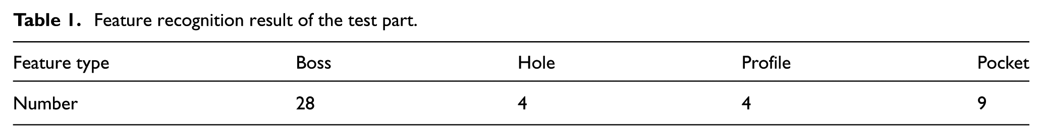
In Feature Recognition module, a machining coordinate system is first assigned to the input 3D part model. Based on the feature classification proposed in the ‘Machining feature classification and extraction for aero-engine casings’ section, four types of machining features are extracted from the part model as shown in Table 1. Feature recognition result could be conveniently evaluated by checking the feature geometry as shown in Figure 16. In the future work of this research, an interactive feature operating function will be added just like what we have done in aircraft structural parts machining 21 to make the feature result editable. After feature recognition is completed, feature result will be saved in an XML file. It should be noticed that the XML file does not contain the detailed geometric properties of the feature but the tag values of the feature faces. If the detailed geometric properties are required by the downstream applications, the corresponding algorithms could find the real faces according to those tag values and then get what they want.
Feature recognition result of the test part.
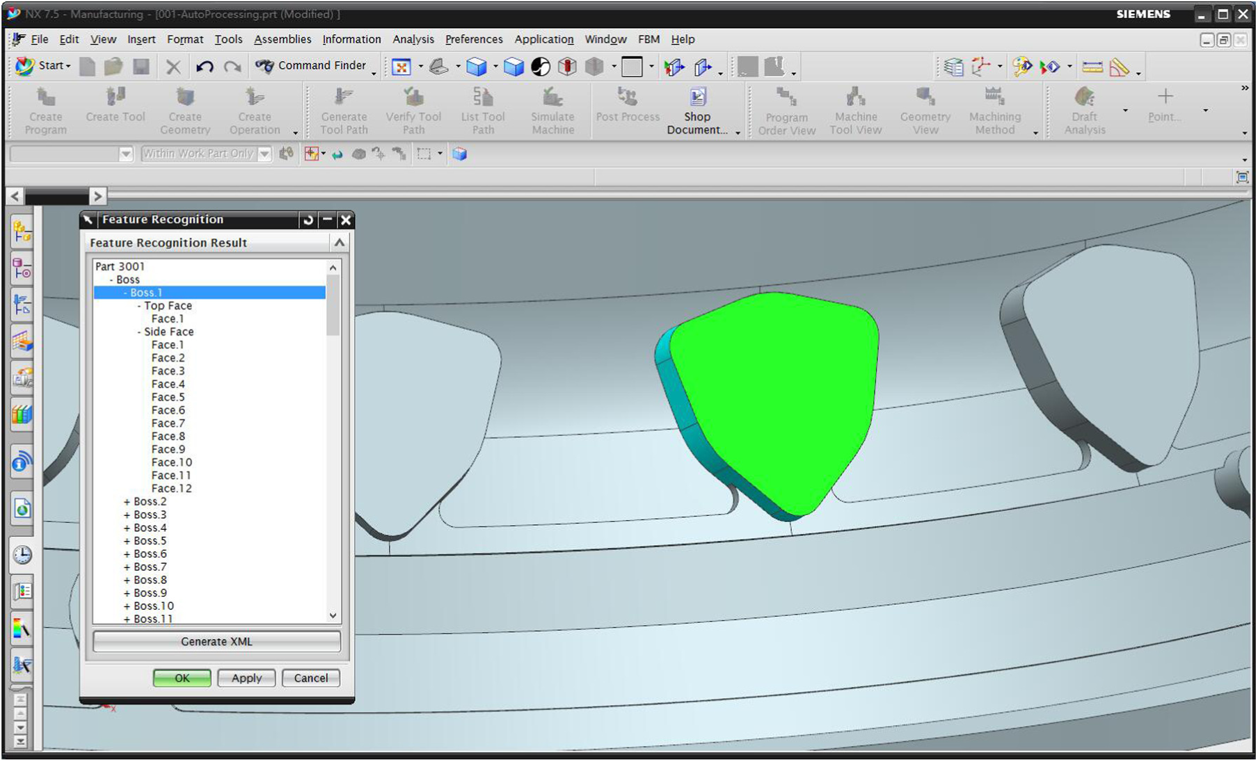
Feature recognition module.
In Machining Operation Planning module, the result of the Feature Recognition module will be operated as the basis to generate machining operations. Although the general machining plans for each feature type are relatively fixed, the details like the cutter dimensions and cutting parameters are various in different factories. Therefore, this module provides two ways to determine these details. One is named as automatic process planning which will automatically select a typical machining plan from the database by analysing the similarity of the part geometry. The other is to read the user-defined process plan which contains the detailed machining information for each machining operation type. Users could also select the feature types that they want to generate the toolpaths. After these necessary settings are finished, the system will automatically construct the machining regions for each machining feature as mentioned in the section ‘Machining region construction for machining features’ and then assign it to the corresponding machining operations. For each machining operation, the system will check whether there is undercut material left according to the method discussed in the the ‘Undercut region classification and detection’ section. The undercut regions will be calculated and additional machining operations will be planned after this process step. After all the machining operations are appended to the process tree, users could display the toolpaths for evaluation or optimisation based on the simulation result as shown in Figure 17. With this system, the semi-finishing and finishing toolpaths are automatically generated in 4 min 47 s. The same task requires 3 h on average by traditional human-based method. The test part is finally machined using the toolpaths generated by the system as shown in Figure 18 and the result shows that it meets the quality requirements well.
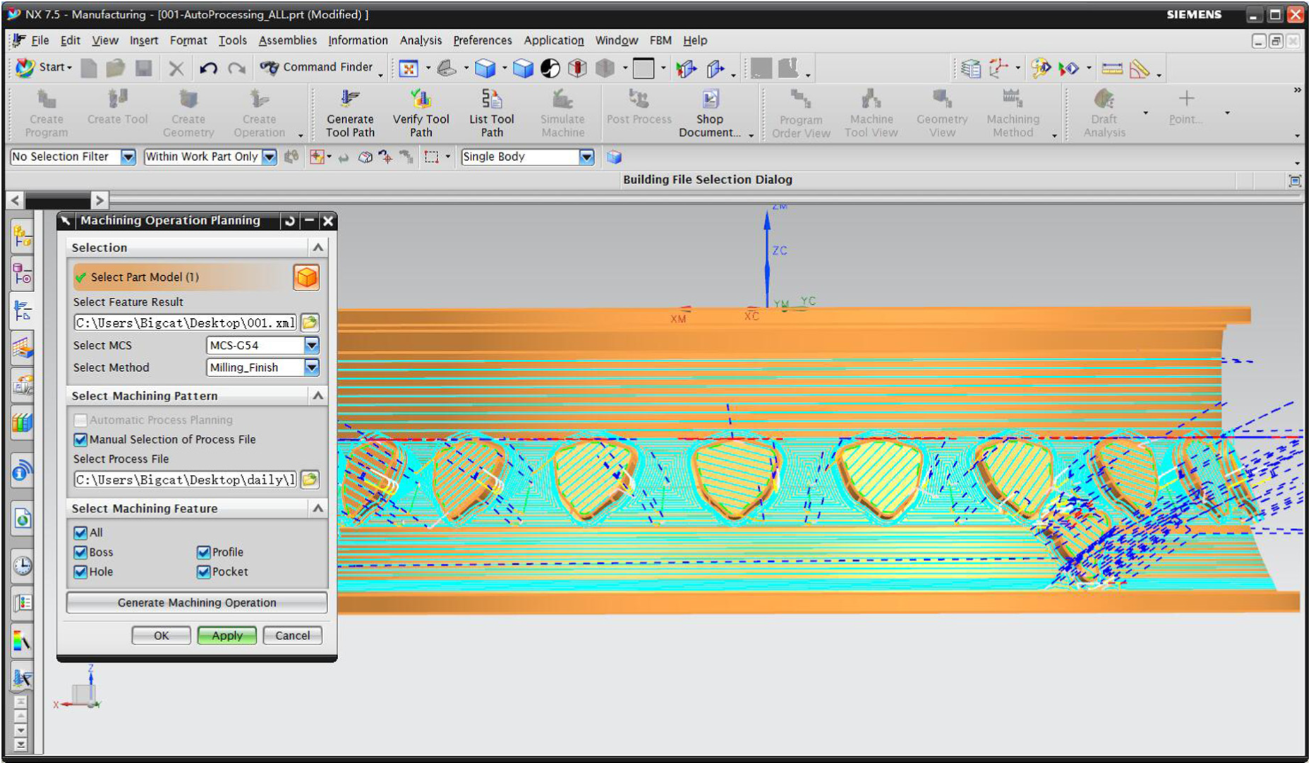
Machining operation planning module.
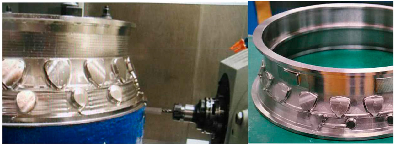
Part machining with the toolpaths generated by the developed system.
Conclusion
Aero-engine casings machining has become one of the most challenging manufacturing tasks in both research and industry and the machining accuracy and efficiency will directly affect the whole engine’s manufacturing quality and cycle. As the bridge between design and real machining, NC programming is one of the most important stages to influence the final machining result. However, traditional NC programming methods based on commercial CAM systems usually require a large number of manual interactions with high-skilled experience, which results in not only low efficiency but also unstable machining quality especially for complex parts like aero-engine casings. This article proposes a feature-based automatic NC programming approach for aero-engine casings. A machining feature classification towards the geometric and machining characteristics of aero-engine casings is given to overcome the deficiencies of existing feature classifications. Then the method to extract machining regions for each feature type is discussed by considering the alternatives between turning and milling conditions. Moreover, as aero-engine casings are mainly made up of high-temperature alloy or titanium alloy, excessive cutting is strictly forbidden during the whole machining process. An undercut detection method is presented to evaluate the interim machining effects after each individual machining operation. By implementing the proposed approach, a feature-based NC programming system is developed on the CAM platform of Siemens NX 7.5 and a real aero-engine casing is chosen to demonstrate how the system works and shows the feasibility of the proposed approach. In future work, the roughing step will be considered and the interactivity of the system should also be improved. Furthermore, more typical machining plans will be considered to optimise the algorithms.
Footnotes
Declaration of conflicting interests
The author(s) declared no potential conflicts of interest with respect to the research, authorship, and/or publication of this article.
Funding
The author(s) disclosed receipt of the following financial support for the research, authorship, and/or publication of this article: The results presented in this article are generated from the projects funded by National Natural Science Foundation of China (No. 51605217).