
Abstract
The wide application of the ball-screw inerter for vibration isolation has made it increasingly important to precisely determine the vibration transmissibility of the isolation system. In this reported work, the transmissibility of a vibration isolation system containing an inerter was predicted by using a complex mass M* in the calculations. The reported theoretical analysis showed that in the design of the type II inerter-spring-damper and inerter-rubber vibration isolation systems, the inertance-mass ratio must be less than twice the damping ratio to achieve improved vibration isolation performance when designing the system. To validate the findings, experimental tests were conducted on the type II inerter-spring-damper and inerter-rubber vibration isolation systems with ball-screw inerter. The experimental results showed that, based on M*, the transmissibility of these two systems was close to the experimental results, which illustrated the rationale for using M*. The results of this reported study will help facilitate the parameter design and performance analysis of a vibration isolation system with an inerter.
Introduction
Vibration and noise control play a central role in the machinery industry, and its related research has become increasingly popular, as illustrated by recent literature reports.1–5 Since noise and vibration isolation performance are key parameters in the design of vibration control systems, an accurate calculation of transmissibility has become increasingly important in the design process. In this regard, Tapia-González et al. experimentally studied the shock and vibration transmissibility of dry friction isolators, 6 Sahu et al. actively controlled transmitted sound through a double panel partition using a weighted sum of spatial gradients. 7 Caiazzo et al. reported on the active control of the turbulent boundary layer sound transmission into a vehicle’s interior. 8 Zhoul and Wenlei reported on the study of the vibration and noise transmissibility characteristics of a gear transmission system. 9
The inerter is a recently proposed concept and device that allows an applied force at two terminals to be proportional to the relative acceleration between them.10,11 The inerter is an extension of the basic mechanical vibration isolation method (i.e. inerter-spring-damper (ISD) vibration isolation system) in contrast to the methods that employ only springs and dampers. An ISD vibration isolation system can comprise other more complex vibration isolation systems, so it is very meaningful to individually analyse an ISD vibration isolation system. Jiang and Smith conducted a series of studies on ISD vibration isolation systems and proposed a passive mechanical vibration network 12 and a design method with an inerter.13,14 As research work in this area has progressed, applications of inerter in general engineering practice has become more extensive. For example, Wang et al. used inerter on the train suspension system15,16 and in the control of vibrations in a building. 17 Hu and Chen and Michael et al. used an inerter in vehicle suspensions18,19 and as vibration absorbers.20–22 Lazar et al. used an inerter in cable damping. 23
As the design and application research of the ball-screw inerter become more precise and successive, the original theory of the vibration isolation performance of the ISD vibration isolation system can no longer meet realistic needs, because of the nonlinear factors.24–27 Actually, an article 28 illustrated nonlinear inertance calculation method of ball-screw inerter, in which friction, nominal radius, lead, contact angle, ball radius and number of balls were considered. Inspired by some researches on nonlinear vibration isolator where used positive and negative stiffness,29–32 compared to the previous methods used to calculate transmissibility,12,15–19 this reported study expressed the mass (M = m + b) as a complex mass (M* = m + bj) and re-established several dynamic equations for a vibration isolation system with ball-screw inerter to deduce transmissibility. The experimental results of this study showed that the transmissibility calculations in this study were closer to the experimental results than those previously reported, especially in a frequency band of 10 Hz.
The remainder of this report can be summarized as follows. In the next section, the classical dynamic equations for an ISD vibration isolation system and the transmissibility were introduced and the vibration mass was initially expressed as a complex mass. In sections ‘Type II ISD vibration isolation system’, ‘Type III ISD vibration isolation system’ and ‘inerter-rubber (IR) vibration isolation system’, the new transmissibility of type II, type III ISD and IR vibration isolation system was analysed and some cases were provided. Section ‘Experimental results and discussion’ experimentally verifies the accuracy of the transmissibility of the system based on the complex mass expression method. The final section summarizes some of the conclusions of this work.
The classical transmissibility of ISD vibration isolation system and definition of complex mass
Classical transmissibility
Figure 1(a) shows a type I ISD vibration isolation system, where the vibration mass m achieves vibration isolation through the parallel inerter b and damper c under it. The type I ISD vibration isolation system is seldom used in engineering, so this study did not employ it for analysis due to limited space. Figure 1(b) shows a type II ISD vibration isolation system, where the vibration mass m achieves vibration isolation through the parallel spring k, inerter b and damper c under it. Figure 1(c) shows a type III ISD vibration isolation system, where the vibration mass m achieves vibration isolation through the spring k, inerter b and damper c under it, where the inerter b and damping c are initially connected in series in, and then in parallel with the spring k. Figure 1(d) shows an IR vibration isolation system where inerter b is in parallel with the rubber under the vibration mass m.
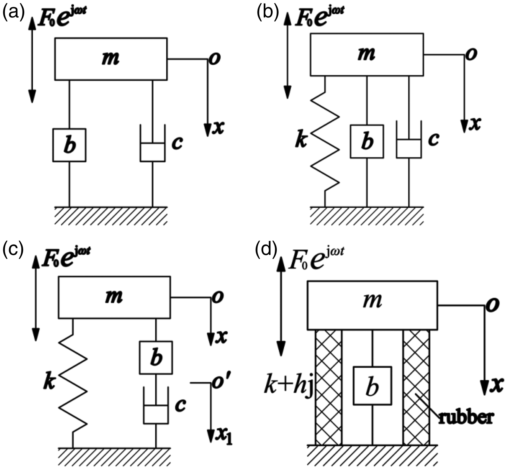
Vibration isolation system with inerter. (a) Type I ISD, (b) Type II ISD, (c) Type III ISD, (d) IR.
The classical dynamic equation for a type II ISD vibration isolation system is

Its transmissibility is
33

The classical dynamic equations for a type III ISD vibration isolation system are

Its transmissibility is
33
Definition of complex mass
The classical theory for an inerter considers that inertial force
Therefore, based on the experimental results, it is necessary to consider the influence of vibration velocity on the inertance when establishing the dynamic equations. This reported study proposed that the inertance should be expressed as the complex inertance, bj, and the mass should be expressed as the complex mass, M* = m + bj. On this basis, the dynamic equations will be re-constructed and the transmissibility will be deduced. The following content will analyse the type II ISD, type III ISD and IR vibration isolation systems.
Type II ISD vibration isolation system
Derivation and analysis of new transmissibility
The dynamic equation for type II ISD vibration isolation system is re-established as

Defining
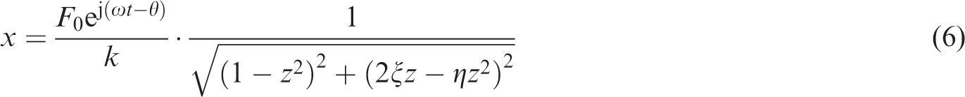
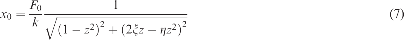
So its amplitude is
The output transmission force after the input excitation force work through the vibration isolation system is

The amplitude of the output transmission force is

According to equations (7) and (9), the transmissibility of type II ISD vibration isolation system can be deduced as

Analysing equation (10), when
To obtain the maximum and minimum transmissibility

Solving equation (11), two positive real solutions are obtained (
With the increase of the frequency ratio, the transmissibility
Setting the denominator of equation (10) at 0 will produce z = 1, η = 2ξ. If z = 1 and η = 2ξ, so the resonant peak of the transmissibility will be infinite. Therefore, the parameters in engineering design of type II ISD vibration isolation system that should be avoided are η = 2ξ.
Case of type II ISD vibration isolation system
Figure 2(a) shows the transmissibility of a type II ISD vibration isolation system with different η when
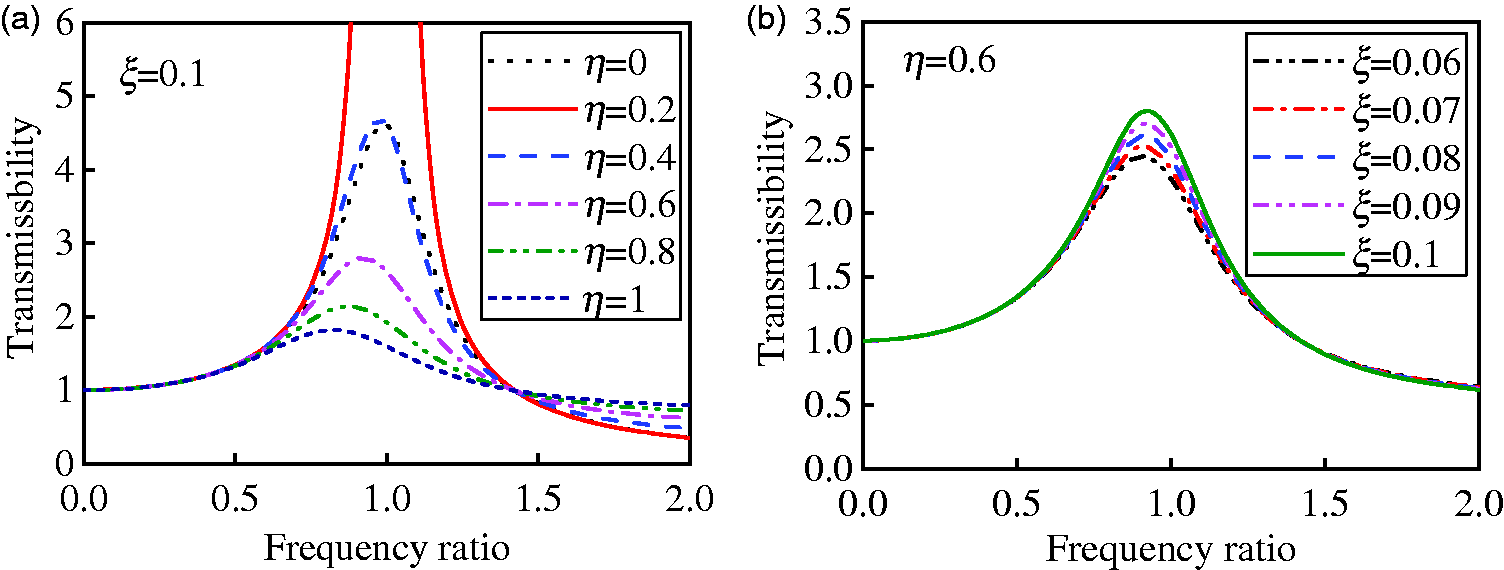
Transmissibility of II type ISD vibration isolation system. (a)
Figure 2(b) shows transmissibility of type II ISD vibration isolation system with different ξ when
Type III ISD vibration isolation system
Derivation and analysis of new transmissibility
The dynamic equations for the type III ISD vibration isolation system can be re-established as

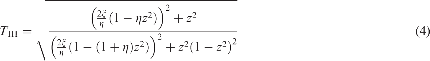
Similarly, the transmissibility of a type III ISD vibration isolation system can be deducted as

Obtaining the derivative of equation (13), and setting it equal to 0, will yield

Based on various conditions, equation (14) may have one or two positive real solutions, which as discussed as follows:
When When
Obtaining the limits of equation (13), the stability value will approach 0, which means that as the frequency ratio increases, the transmissibility becomes smaller, and its vibration isolation performance becomes better.
Case of type III ISD vibration isolation system
Figure 3(a) is the transmissibility of a type III ISD vibration isolation system with different
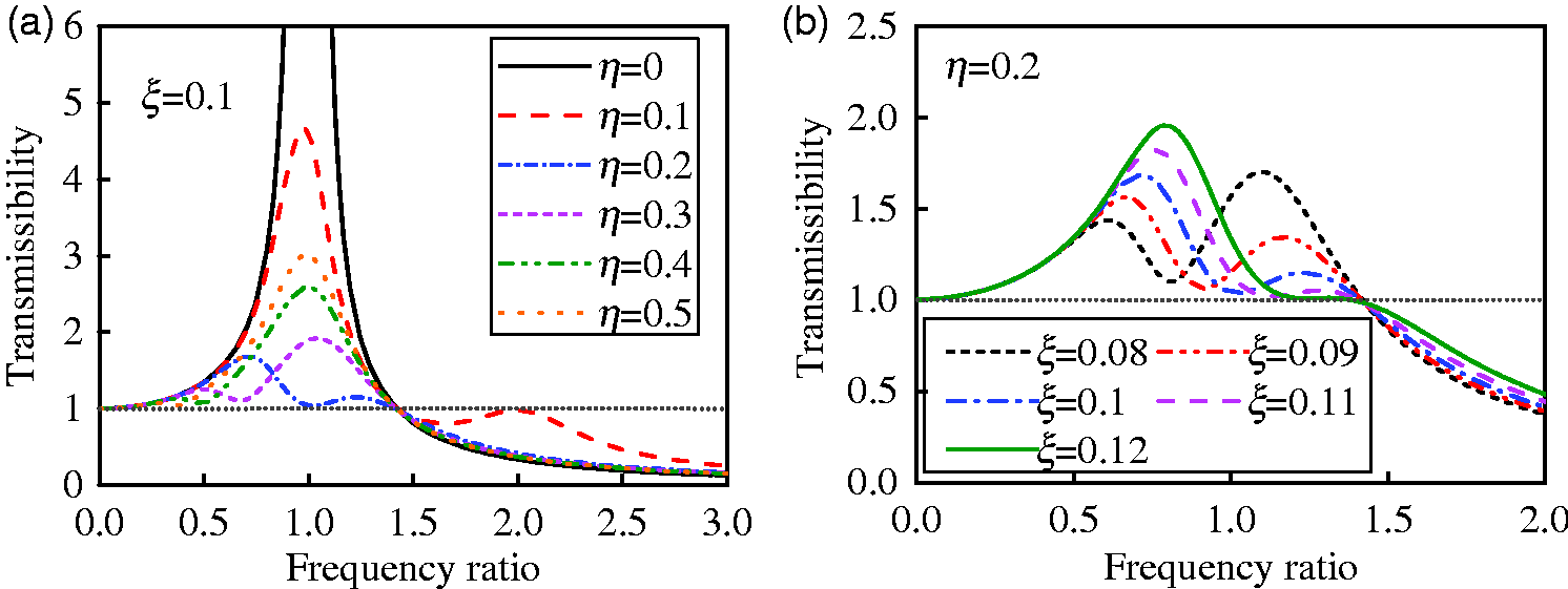
Transmissibility of III type ISD vibration isolation system, (a)
Figure 3(b) shows a type III ISD vibration isolation system transmissibility with different
IR vibration isolation system
Derivation and analysis of new transmissibility
As shown in Figure 1(d), an IR vibration isolation system is a vibration isolation system where the inerter is parallel with the rubber. When the elastic element of the vibration isolation system is rubber, there is no damper, so for the stiffness of the rubber, it is more realistic to use the complex stiffness
The dynamic equation for the IR vibration isolation system can be expressed as

From this, the transmissibility of the IR vibration isolation system can be deduced as

Using equation (16), when
Obtaining derivative of equation (16), and make it equal to 0, we get
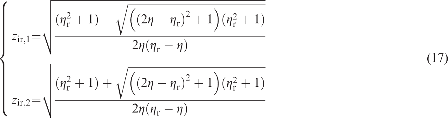
When
When
When
When
Case of IR vibration isolation system
Figure 4(a) is transmissibility of an IR vibration isolation system with different
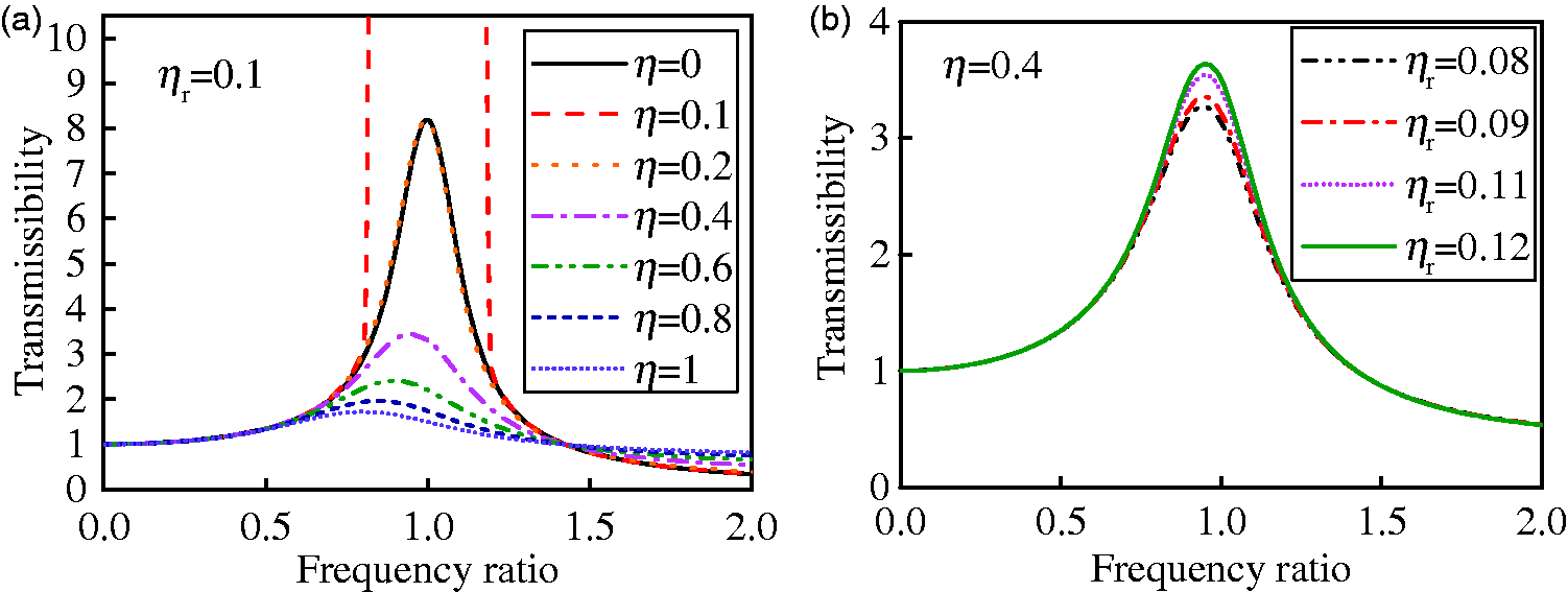
Transmission rate at different circumstances of IR vibration isolation system, (a)
Figure 4(b) is the IR vibration isolation system transmissibility with different
Experimental results and discussion
Experimental results
There are many types of inerter including the hydraulic types34,35 and the mechanical types 36 which include ball-screw inerter and rack-pinion inerter. Ball-screw inerter is the most widely used inerter and offers many advantages in terms of high precision transmission and small backlash. The up and down linear motion and the rotary motion of the inerter can be varied by its ball-screw mechanism. 11 Therefore, this study used a ball-screw inerter as the experimental device to verify the rationale for the mathematical expressions of the mass as complex mass M* and the accuracy of the derived transmissibility of the vibration isolation system with ball-screw inerter. The experimental device was a type II ISD and IR vibration isolation system, so it was tested for its vibration transmissibility for two vibration isolation systems under the following conditions.
Figure 5(a) shows the experimental apparatus of type II ISD vibration isolation system. At the bottom is a variable frequency motor in parallel with four spring dampers (weak damping) and a ball-screw inerter, the system is equivalent to the type II ISD vibration isolation system. At the foundation of the vibration isolation system and the motor base, a number of acceleration sensors were installed. The system was tested with the following conditions, vibration originated from the running motor, which produced a single-frequency sinusoidal excitation in the range of 1∼10 Hz frequency. This was the main operating frequency range of the inerter, once every 1 Hz.
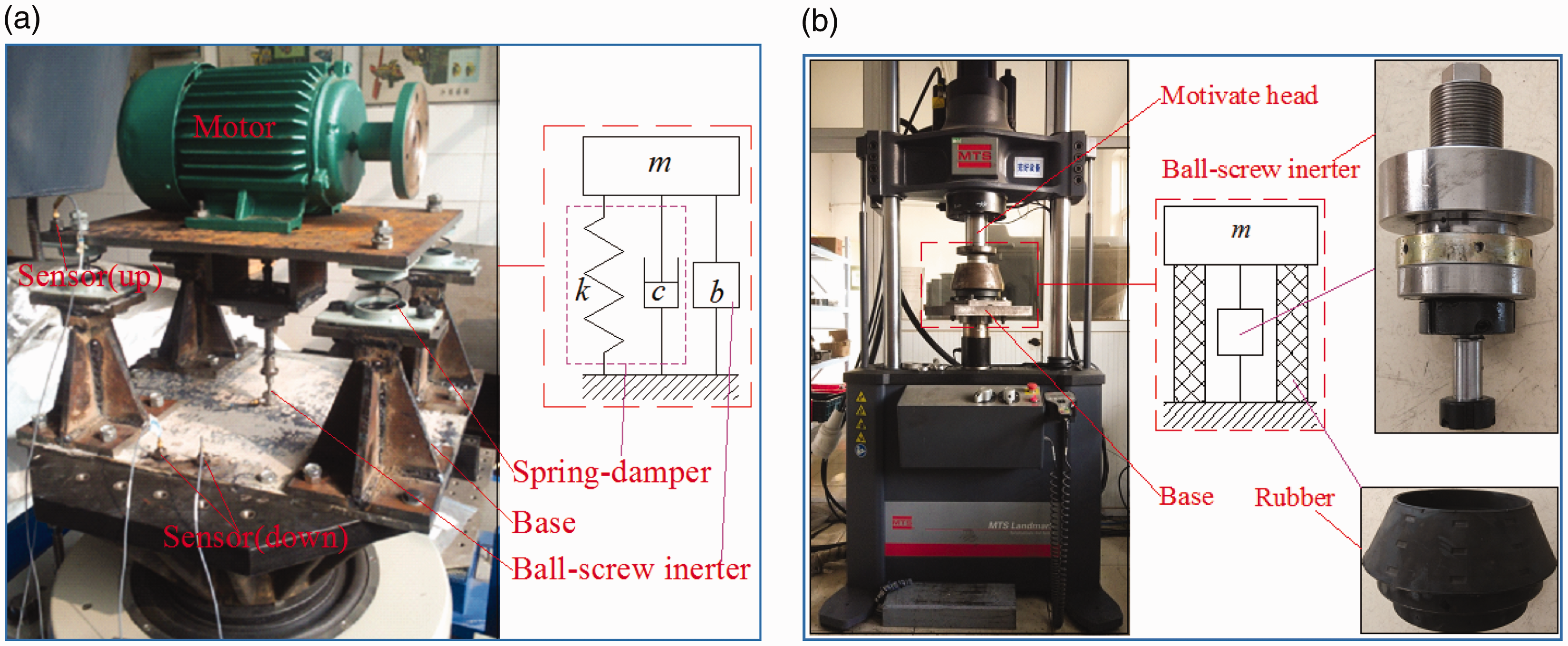
Experimental site and equipment. (a) Type II ISD vibration isolation system. (b) IR vibration isolation system.
As shown in Figure 5(b), the excitation platform was a general type vertical electro-hydraulic servo test system of MTS Landmark series made by MTS, the USA, its maximum load is 500 kN. The platform can adopt a variety of high-precision and highly repeatable durability tests. We fixed the composite vibration isolation device on the platform so that in the composite vibration isolation device, the inerter was in parallel with the rubber. The composite vibration damping device was preloaded with a static load of 20 kN. The excitation head of the MTS added an amplitude of 1 mm sine excitation, in the range of 1∼10 Hz, which was the main operating frequency range of the inerter.
The parameters for the type II ISD and IR vibration isolation systems are shown in Table 1. After analysis, the results for the transmissibility of the type II ISD and IR vibration isolation systems are shown in Table 2.
Parameters of vibration reduction components.
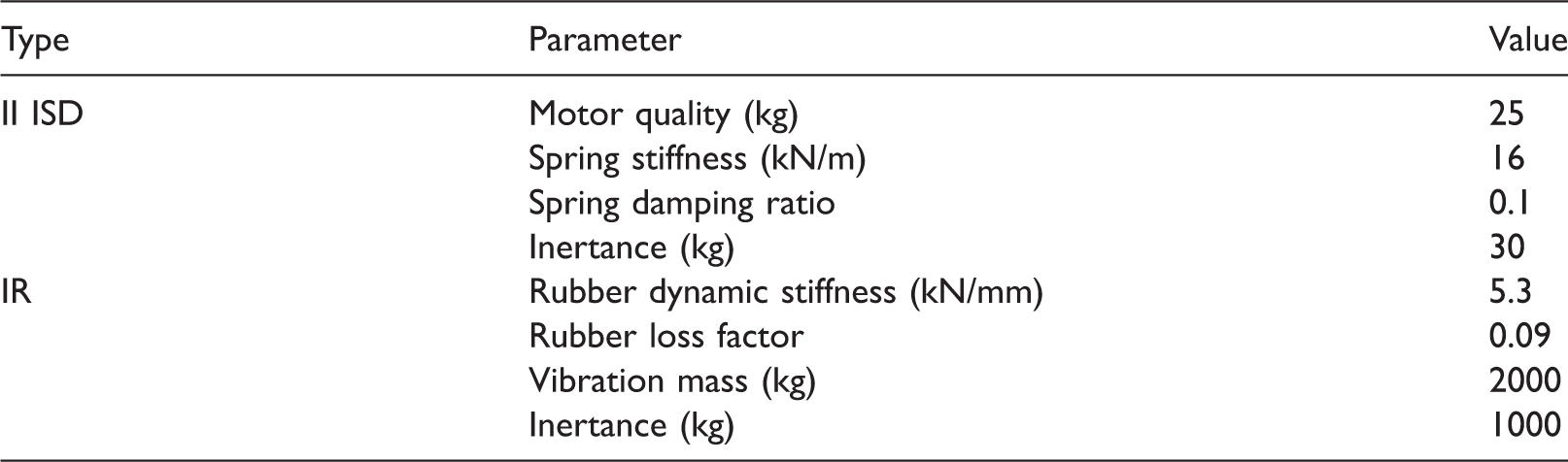
IR: inerter-rubber; ISD: inerter-spring-damper.
Transmission rate test results.
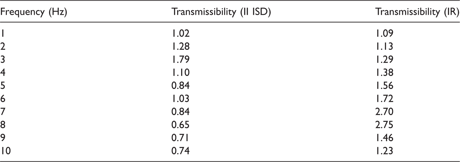
IR: inerter-rubber; ISD: inerter-spring-damper.
Figure 6(a) shows a comparison of the vibration transmissibility of various types of type II ISD vibration isolation systems obtained using different methods. The experimental results show that the transmissibility
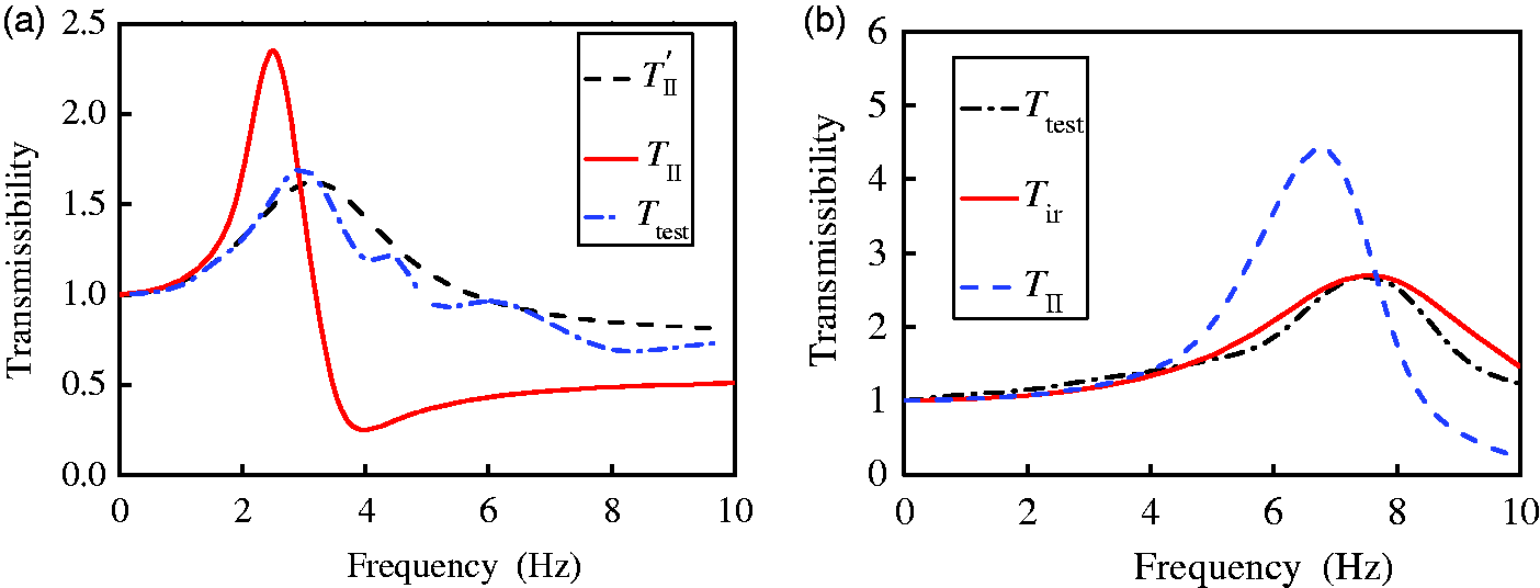
Vibration transmissibility obtained using different methods. (a) Type II ISD vibration isolation system, (b) IR vibration isolation system.
Figure 6(b) shows transmissibility comparison of the IR vibration isolation system obtained using the different methods. The experimental results show that the transmissibility
Discussion
Simple models of the type II ISD, type III ISD and IR vibration isolation systems were analysed in this reported study, but when used in the vibration isolation systems of vehicles, trains, buildings, ships, etc., these three models are widely used.
For example, Figure 7(a) shows a one-quarter vehicle suspension system that includes a type II ISD vibration isolation system. When designing this vehicle suspension, using the classical transmissibility calculation method, a greater error will be introduced than the transmissibility calculation method described in this reported study. Figure 7(b) shows a side view of a marine engine vibration isolation system. Generally speaking, each marine engine has at least six vibration isolators, and if the design of these is based on the classical transmissibility
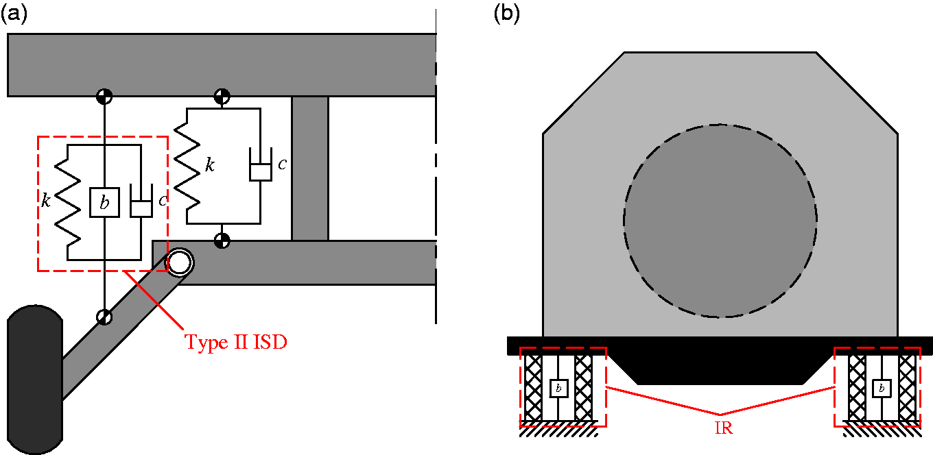
Different vibration isolation systems. (a) One-quarter vehicle suspension. (b) Marine engine vibration isolation system (side view).
Using these above examples, it can be seen that many complex vibration isolation systems can be constituted by the three models detailed in this study, so that analysis of systems using these three models can be very practical. This study discussed only the two-dimensional models using the complex mass method. Furthermore, the three-dimensional models should be employed in future work to obtain a more accurate transmissibility calculation method.
Conclusions
This reported study was initiated to predict the vibration isolation performance of a vibration isolation system with ball-screw inerter and to facilitate engineering design, using a theoretical analysis that employed a complex mass (M* = m + bj). The dynamic classical equations for vibration transmissibility were re-constructed and the transmissibility was reanalysed. In addition, the predictions of transmissibility were verified experimentally. The key conclusions of this work can be summarized as follows:
In the low-frequency range, the average error between the new method for calculating transmissibility that was based on the complex mass and the experimental results was less than 10%. Therefore, the complex mass representation method is reasonable, and the determination of transmissibility based on complex mass is more accurate than using the classical method. When the frequency ratio As the frequency ratio increased, the transmissibility of the type II ISD vibration isolation system and the IR vibration isolation system eventually approached In designing the type II ISD and IR vibration isolation systems, When designing a type II ISD vibration isolation system,
In summary, the transmissibility of a vibration isolation system with ball-screw inerter can be mathematically obtained by considering a complex mass M* = m + bj.
Footnotes
Acknowledgement
The authors would like to thank Jiangsu Tieke New Material Co. Ltd for providing the test equipment, which is vital for this study. They also thank the reviewer and the editor for their time and their valuable comments.
Declaration of conflicting interests
The author(s) declared no potential conflicts of interest with respect to the research, authorship and/or publication of this article.
Funding
The author(s) disclosed receipt of the following financial support for the research, authorship and/or publication of this article: This work was supported by the Science and Technology Department of the Jiangsu Province (project: industry foresight and common key technology) under the grant no. BE2017120.