
Abstract
The paper describes an establishment of dynamic characteristics of the newly created passive mechanical system for isolation of low-frequency (0.7 Hz–50 Hz) vibrations. The many metrological means are sensitive to mechanical vibrations and acoustic noise of low frequency. Such may appear both outside and inside a building, i.e. may be caused by wind, heating, aeration, air conditioning equipment, moving vehicles and other. In the paper, description of the theoretical and experimental tests is provided. The obtained dynamic characteristics (transmissibilities) of the passive mechanical low-frequency vibration isolation system show that such a system is able to isolate vibrations effectively in the frequency range of 0.7 Hz–50 Hz. The results of the experimental tests support the results of the theoretical research.
Keywords
Introduction
A majority of metrological means are sensitive to low-frequency mechanical vibrations and acoustic noise. Such vibrations may appear both outside and inside a building, i.e. may be caused by moving vehicles, wind, operation of heating, aeration, air conditioning equipment and other laboratory equipment. It is known1,2 that the primary micro-seismic frequency achieves 0.07 Hz and the frequency of the secondary micro-seismic vibration is 0.14 Hz and can be of higher amplitude. Usually, frequencies of vibrations of buildings vary between 0.1 Hz and 1.0 Hz and the typical frequencies of floor vibrations vary between 10.0 Hz and 50.0 Hz in the vertical direction and between 1.0 Hz and 20.0 Hz in the horizontal direction. So, isolation of low-frequency vibrations is relevant and necessary for ensuring the required quality of operation of sensitive measuring equipment.
There are abundant technical solutions that enable to mitigate and reduce vibration transmission from a part of a machine to its other parts. In general, they are referred to as vibration isolators (dampers) or suspension mechanisms, such as various absorbers, elastic pillows, various mechanical springs, pneumatic and hydraulic equipment as well as various combinations of them. 3 The need in vibration isolation increasingly grows, because high-precision weighing machines, optical microscopes and other sensitive equipment usable in satellites and orbital stations as well as orbital telescopes4–7 should be isolated from vibrations in order to ensure their proper operation.
Vibrating nano-scales of measuring equipment, such as atomic microscopes, cause abundant problems related to the accuracy of measurements when they are carried out in dynamic modes. At present, several methods (active and passive) for isolation of low-frequency vibrations exist; however, each of them distinguishes for certain advantages and imperfections. Passive vibration isolation systems generate less heat, as compared with active systems, and it is important while working with means sensitive to temperature. In addition, passive systems are much cheaper and more reliable than active ones and require no special means for damping or stiffness control.
At present, passive vibration isolations systems, such as optical tables with pneumatic vibration isolators at laser centres, are widely used for isolation of low-frequency (from 4–5 Hz) vibrations. The typical vibrations of an optical table are in the range between 2.0 Hz and 7.0 Hz that conforms to the natural resonance frequency of the optical table on pneumatic supports. 2 However, for very low frequencies (from 0.7 Hz), better isolators are required to ensure better results while working with probe microscopes and interferometers. The created isolators of quasi-zero (negative) stiffness resonate from 0.5 Hz. This frequency is almost free of energy because it would be too unusual to obtain considerable vibrations at the frequency of 0.5 Hz. 8 Optical tables and active systems do not operate well in vacuum, in particular, at a very high or low temperature. Such a medium may take place on carrying out special tests with semiconductors. The created systems of quasi-zero (negative) stiffness may operate in vacuum as well as at high and low temperatures. Such systems are compact and are easily movable from one place to another. Sometimes optical tables with systems of quasi-zero (negative) stiffness should be used because they enable to mitigate inconsiderable changes of weight and large shifts. 9 In addition, systems of quasi-zero (negative) stiffness are fit for isolation of laser vibrations. The base of a laser is an interferometer, that is, a device sensitive to external vibrations. Usually, its mechanical guides are very long and they make it more sensitive to vibrations. To ensure high quality of modern sophisticated ellipsometric equipment, the level of impact of the external noise should be low and enable to set the edge positions. A properly isolated interferometer enables achieving the maximum resolution. Vibration isolation systems with 0.5 Hz of quasi-zero (negative) stiffness ensure the proper isolation, whereas other systems are not able to do so; and active vibration isolation systems require additional external power supply sources and special maintenance.
In the research, the attention was focused to establish a capability of passive mechanical vibration isolation systems to isolate low-frequency (0.7 Hz–50.0 Hz) vibrations. Although the carried out tests are applied for dealing with specific tasks related to establishing the dynamic characteristics of vibration isolation systems, their results are the ones of wide applicability and may be used for developing vibration isolation systems of the new generation that distinguish for qualitatively new features.10,11
The object of research
In course of development of the system, the phenomenon of quasi-zero stiffness described in Zotov 12 was applied. The system is intended for isolation of vibrations of precise equipment, in particular for many-directional vibration isolation suspensions that distinguish for low stiffness and strong damping of resonance phenomena of the system (Figure 1). The mechanical vibration isolation system of quasi-zero stiffness protected by the Patent LT 5857 of Republic of Lithuania 11 consists of an upper pallet 1 supporting on a totality of components of vertical and horizontal vibration dampers interconnected by an elastic structure. The said totality of the components is based on the lower base plate 2 with the tightening control equipment for the supporting vertical spring 5 in its centre. The equipment is adjusted in such a way that one end of the spring 5 (chosen according to the mass of the load) through the supporting surface of the central rod 6 fixed in its centre ensures the vertical stiffness and the set position required for the functionality. The elastic interaction of the other end of the spring with the horizontal set of levers ensures the quasi-zero stiffness (of a direction opposite to the stiffness caused by the first end of the spring) required for the functionality. For vertical stiffness control, a worm-and-worm gear where a worm 3 is tightly fitted on the base plate 2 and the worm-wheel 4 is concentrically fixed on the supporting threaded bush 7 are used. The central rod 6 freely passes through the internal hole of the bush. The bush is protected against swing because one end of it leans upon the base plate, while the other end upon the supporting spring. The supporting surface of the central rod is the lower surface on the upper part of the horizontal damping block 8 connected with the rod. The said block is formed of two parts. The lower part 17 is rigidly connected with the lower end of the central rod. With the upper end of the rod, a part of the block is connected by four rigid rods 9 situated at the same distances from the centre and freely passing through the base plate. These rods act as levers because of an ability of slight horizontal mobility that is predetermined the adapted structure of the damping block. The upper part of the horizontal damping block is linked with the base plate via the housings 10 and 11. One of them (10) is rigidly fixed to the base plate and the other (11) situated in the opposite side is rigidly fixed to the said plate by its lower part only. The latter is the housing for fixing flat springs 12 connecting it with the upper part. Because of this, the upper part of the housing is of low mobility and, in its turn, causes a need in slight vertical mobility of the upper part of the damping block. It is accomplished by articulated mounting of ends of rod pairs of the horizontal damping blocks into the upper parts of the above-mentioned housings 10 and 11, on one side, and to the upper part of the damping block 8, on the other side. Between the ends of the hinges formed in the said way, at least one horizontal hydraulic damper is mounted. The block tightening screw 13 through a hole in the central plate (that connects the ends) freely passes the central rod of the system and is tightened by controllable spring 14. The mechanical vibration isolation system of quasi-zero stiffness is provided with three or four supports 15 rigidly fixed to the base plate for propping against the weight of the object’s platform and the suspension 16 for damping the platform tilt. The suspension is rigidly connected with the supporting surface of the central rod. The hydraulic dampers are mounted into horizontal holes in the immovable housings 10 and 11 of the block of dampers; the said housings are connected with the base plate 2 and their grooves are filled with a viscous liquid. The dampers can freely swing in their holes. In addition, their ends are sealed by gaskets with horizontal rods (that are situated in the same distances from the axis of the damping block) rigidly fixed on them. For different masses of the object, different support springs are chosen. The object’s pallet – through the central rod, the lower plate of the damping block and the remaining elastic structure of the system – is hung on the rods of a fixed stiffness.
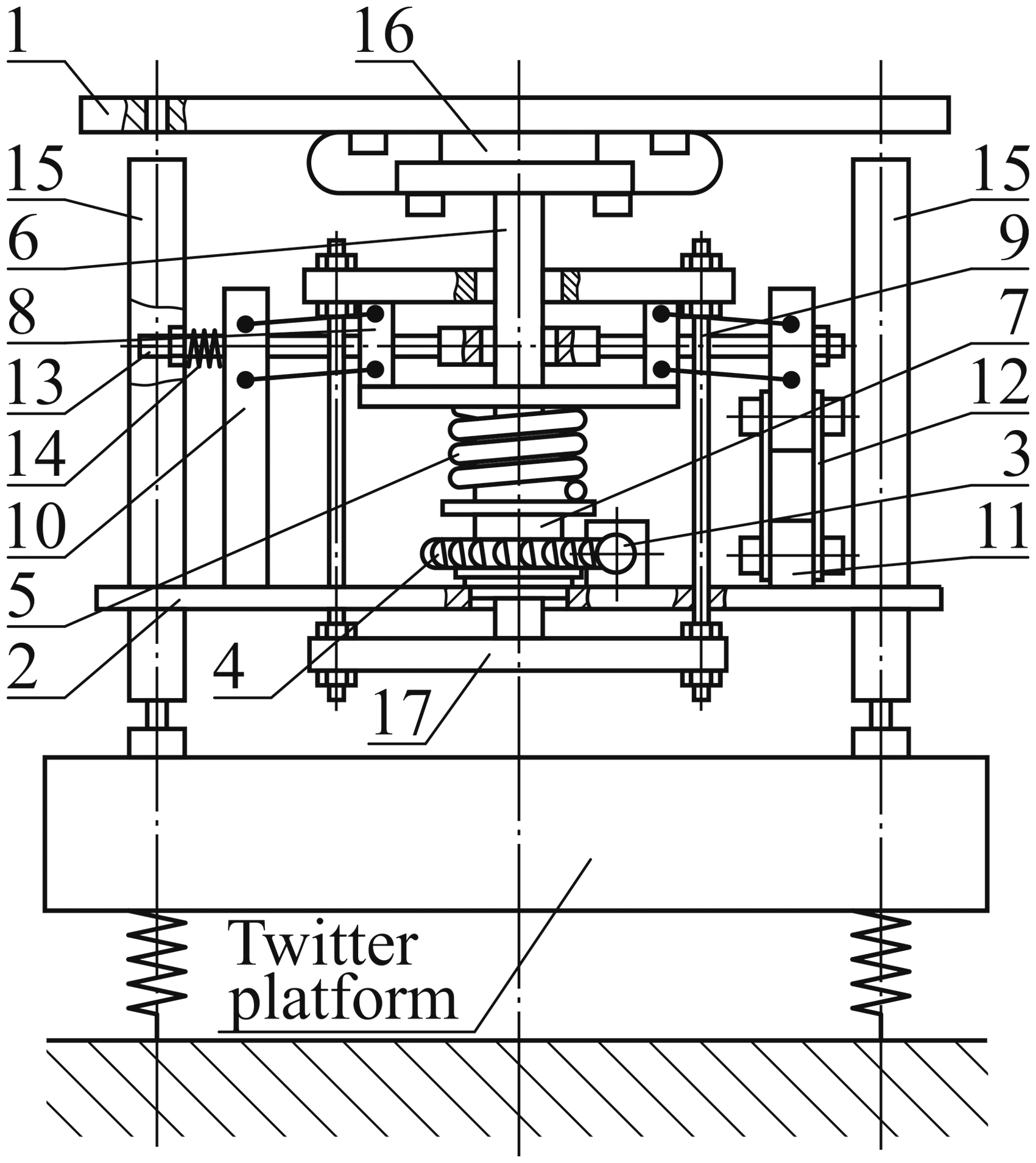
System of isolation of quasi-zero stiffness on a vibrating platform. 11
Dynamic tests
The dynamic model of the vibration isolation system of quasi-zero stiffness is shown in Figure 2(a) and (b).
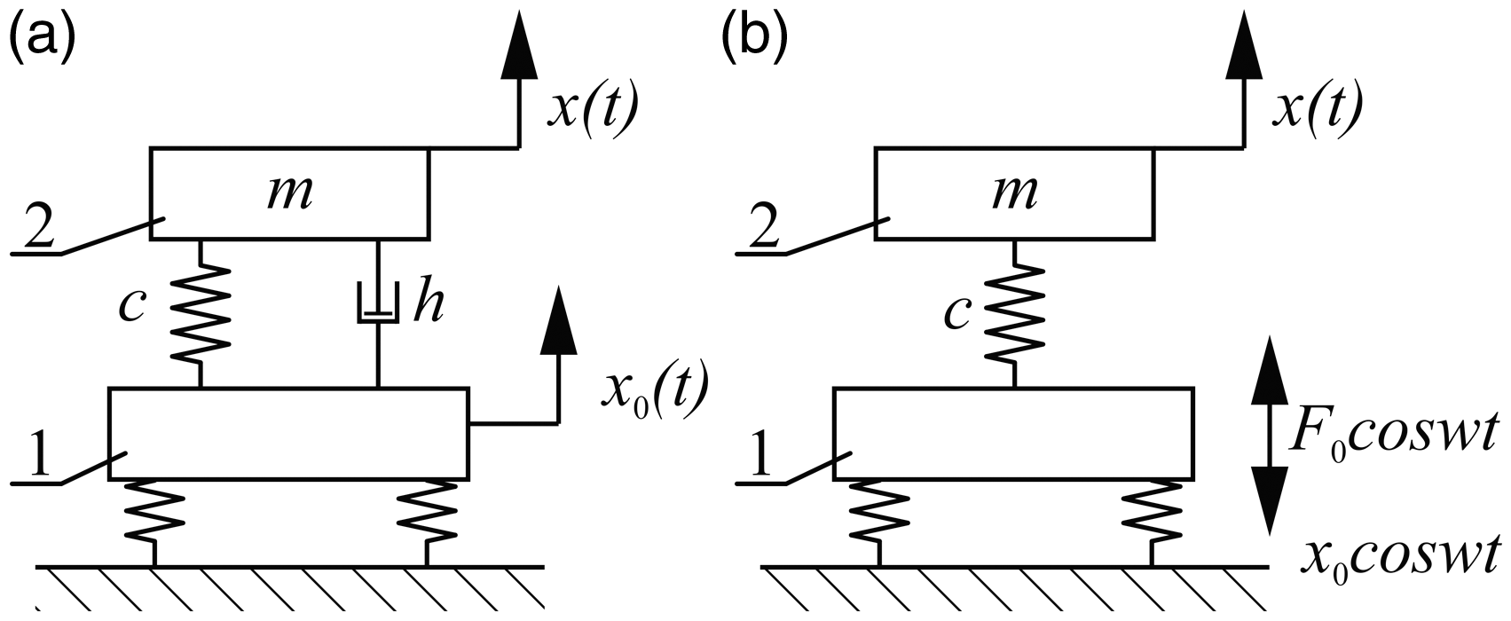
Dynamic models of quasi-zero stiffness vibration isolation: (a) with elastic–viscous damping; (b) with elastic damping (1 – vibrating platform, 2 – vibration isolation system of quasi-zero stiffness).
The differential equation of the system’s movement (Figure 2(a)) when the movement of the platform is harmonious will be expressed as follows

If we insert equation (1) into the expression of the platform movement

If the platform is excited by harmonious frequency
When only hysteresis damping exists in the system, the transmissibility will be expressed as follows
The diagrams of the said transmissibilities are shown in Figure 3(a) and (b).
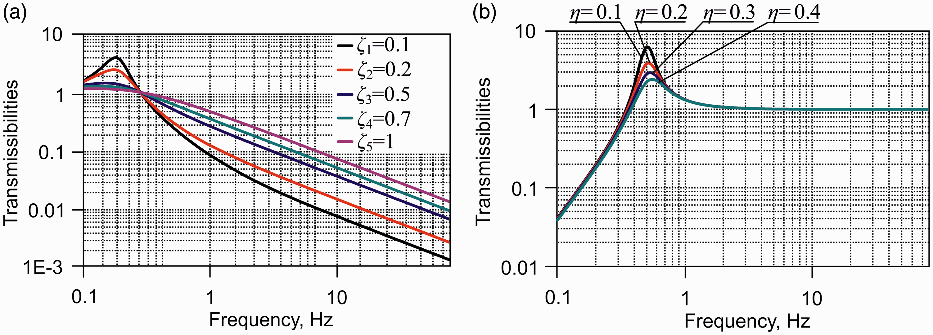
Transmissibilities: (a) at viscous–elastic damping and (b) at hysteresis damping.
Experimental tests
The scheme of the research, i.e. exploring the vibration isolation system of quasi-zero stiffness is shown in Figure 4. For the tests, devices for measuring and analysis of vibrations and other dynamic characteristics were used. They include an impact hammer 8202 from “Brüel & Kjaer” with a force measurement transducer 8200, an amplifier 2626 and movable measurement result handling equipment “Machine Diagnostics Toolbox Type 9727” with computer DEEL as well as vibration sensors 8341 and 8306 with vibration meter 2511, etc.
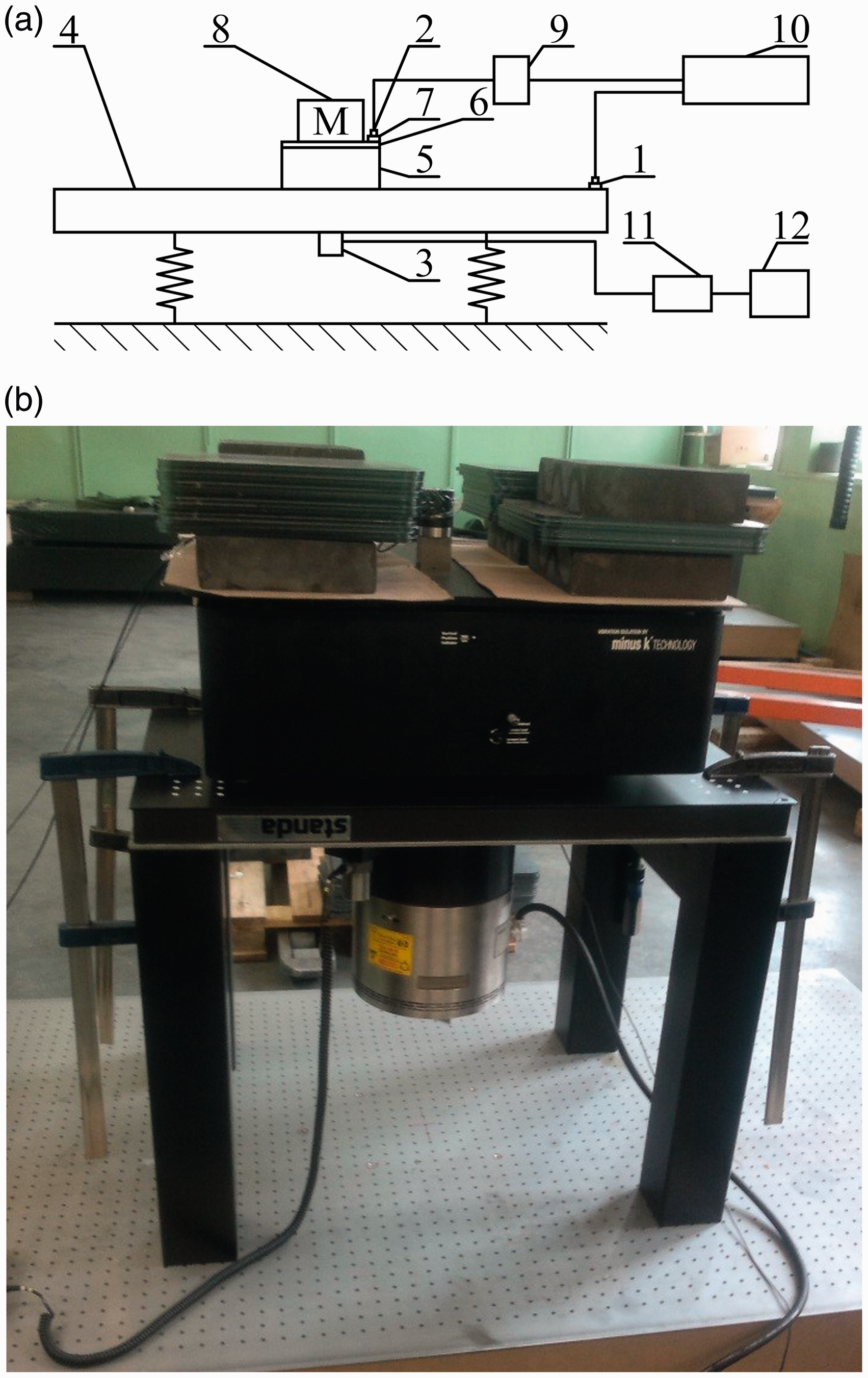
Excitation of vibrations by use of vibrator (a) scheme of the research stand and (b) photo of the stand (1 – seismic accelerometer 8318; 2 – seismic accelerometer 8306; 3 – vibrator; 4 – vibrating platform; 5 – vibration isolation system of quasi–zero (negative) stiffness; 6 – fixing plate; 7 – orienting log; 8 – mass 200 kg; 9 – vibrometer 2511; 10 – movable equipment of result handling “Machine Diagnostics Toolbox Type 9727” with a computer DELL; 11 – amplifier 2706; 12 – vibration generator 1027).
For exploring the dynamic parameters, a platform for excitation of vibrations with a vibrator and other special research equipment was used and tested. The vibrator generated harmonious, impulse and random (white noise) vibrations in the range of 0.1 Hz–50.0 Hz in the vertical direction.
The measuring signals were processed by a computer upon applying the set of programmes “Origin 7.5”.
In the scheme shown in Figure 4(a), the seismic accelerometer 8306 (pos. 2) is provided on the orienting log 7. The orienting log 7 is fixed on the fixing plate 6, which in turn on the vibration isolation system of quasi-zero (negative) stiffness 5.
In the expanded diagram of the excitation signal provided in Figure 5(a), the maximum value of the amplitude of acceleration is equal to 7.64 m/s2 at the moment 0.236 s, whereas the amplitude of acceleration of the damped signal at the same moment (Figure 5(b)) is equal to –0.00031 m/s2.
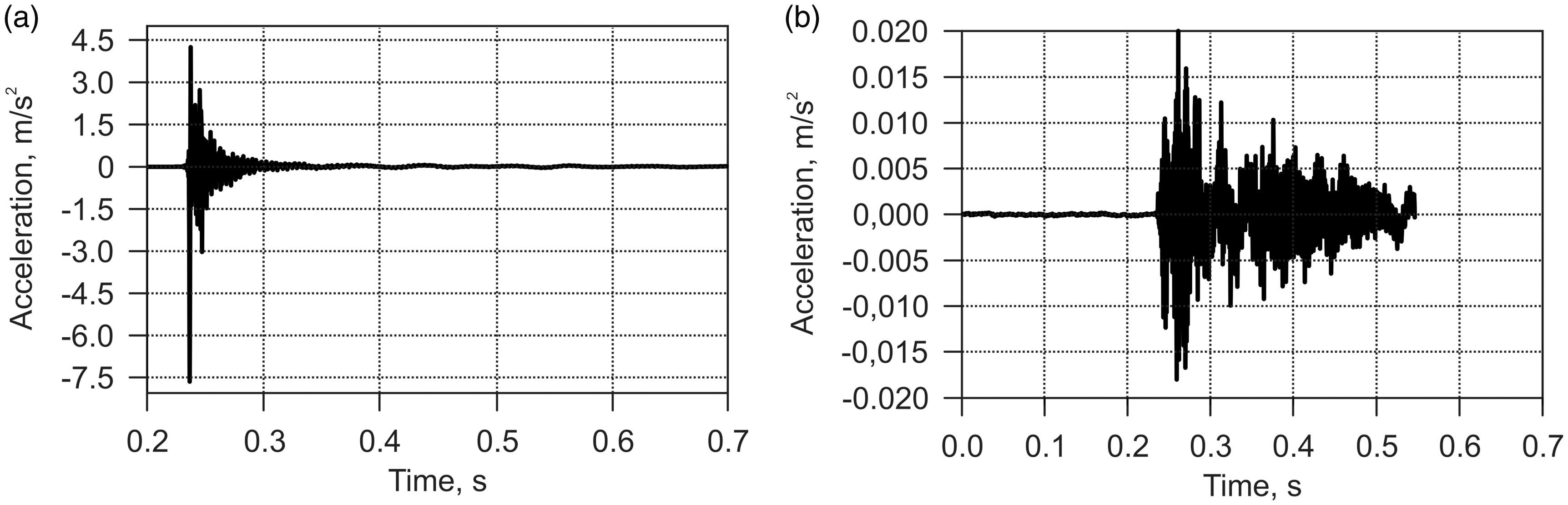
Expanded impulse excitation signals on platform (a) and on a system of quasi-zero stiffness (b).
The time characteristics visually show the dynamic properties of the system in the zone of the time t (Figure 6(a) to (e)).
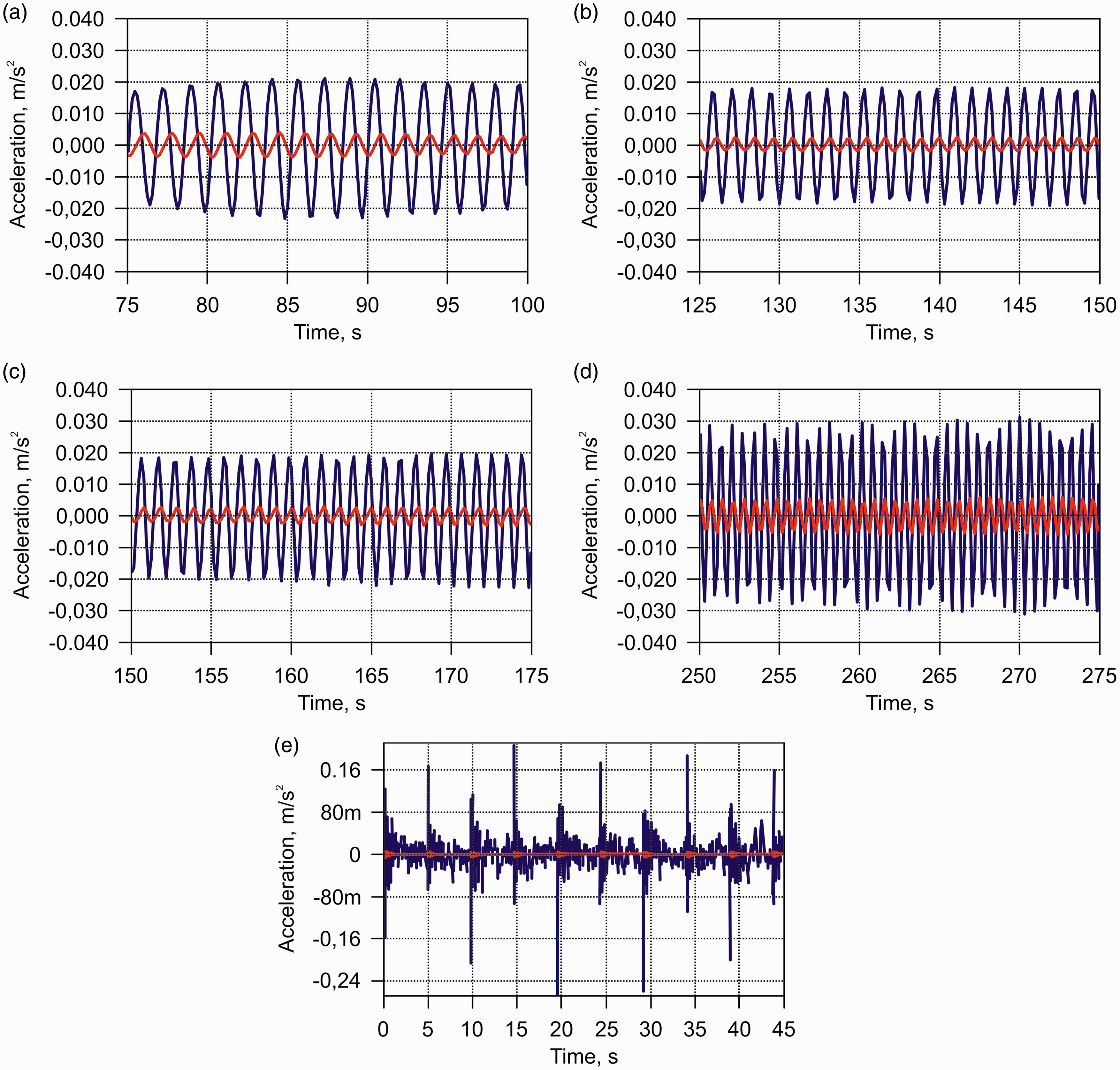
Isolation of vibrations of quasi-zero (negative) stiffness (blue signal – platform, red signal – of a researched system): (a–d) harmonic excitation, 0.6 Hz; 0.8 Hz; 1.0 Hz; 1.5 Hz; (e) impulse excitation.
While using higher frequencies, it was found that when the platform is excited by 2.0 Hz frequency, the amplitude of the vibrations on the system of quasi-zero (negative) stiffness decreases 18 times, when it is excited by 4.0 Hz frequency – 90 times and when excited by 10.0 Hz – the amplitude of the vibrations decreases 100 times. So, low frequencies are isolated effectively. The diagram of transmissibilities of such a system in case of harmonious excitation is shown in Figure 7.
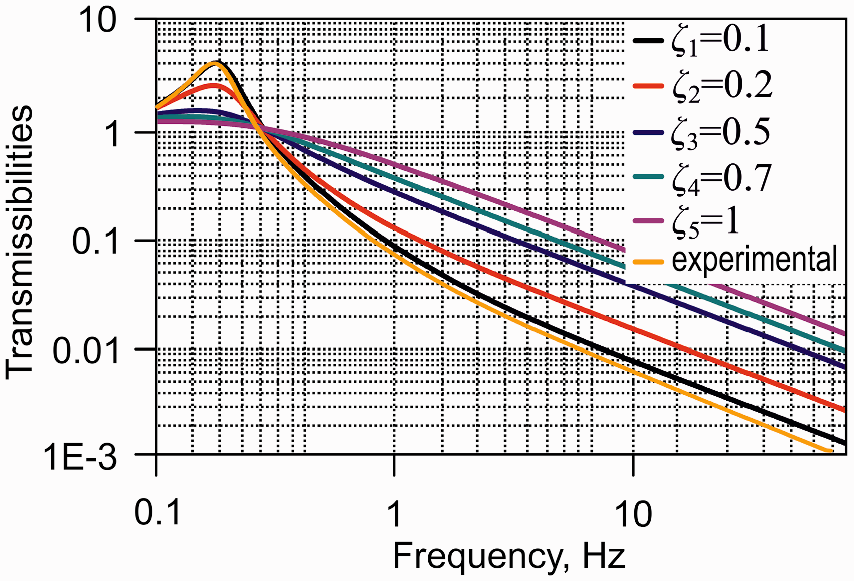
Transmissibility diagram of isolation system of quasi-zero stiffness (comparison of experimental data with theoretical results).
We can see from the curve provided in Figure 7 that vibration isolation starts at the frequency of 0.7 Hz and occurs effectively up to the frequency of 100 Hz. In comparison with the theoretical transmissibility (Figure 3(a)), it may be seen that the value of the damping coefficient is between 0.1 and 0.25, the discrepancy error at various frequencies varies from 0.5% to 1%. As compared to transmissibility of a system of negative stiffness provided in literature,6,14 it may be seen that the isolating abilities of a system of quasi-zero stiffness are better in the frequency range from 0.8 Hz to 3.0 Hz; however, they are similar at other frequencies as well.
Conclusions
The created mechanical low-frequency vibration isolation system of quasi-zero stiffness and the analytical research of it showed that vibration isolation started at the frequency of 0.7 Hz and the efficiency of isolation grew with increase of the frequency. In course of the experiments, it was found that a vibration isolation system of quasi-zero stiffness isolated well the low-frequency vibrations in the frequency range of 0.7 Hz–50 Hz. The discrepancy error between the theoretical and experimental vibration transmissibility at various frequencies varied between 0.5% and 1%. Upon applying the created passive mechanical low-frequency vibration isolation system the vibration isolation process was considerably simplified; in addition, it becomes cheaper and requires less time and labour input as compared to other isolation methods applicable at present.
Footnotes
Declaration of conflicting interests
The author(s) declared no potential conflicts of interest with respect to the research, authorship, and/or publication of this article.
Funding
The author(s) received no financial support for the research, authorship, and/or publication of this article.