
Abstract
Modal analysis and flutter computation of a complex tail cabin system including six all-movable rudders for hypersonic flight vehicle was studied in this paper. Recently, some complex all-movable rudder system has been applied to hypersonic flight vehicle. Many investigations were taken to analyse a single all-movable rudder, such as modal analysis, flutter analysis, aero-heating analysis, etc. But most of existing investigations emphasized on single rudder. In this paper, a complex tail cabin system including six all-movable rudders from the X-51A vehicle was investigated. Modal analysis was presented based on accurate finite element modelling and bending and twisting modes of the structure were computed. Ground vibration test was provided to confirm the accuracy of computation. Then flutter characteristic of this complex system was analysed based on doublet lattice method. With flight Mach number 3 and 4, flutter analysis relating to both symmetric mode and antisymmetric mode was presented. It can be found from the presented results of flutter analysis that there were obvious and non-negligible coupling vibration effects among rudders in such a complex rudder system. So flutter characteristic of hypersonic flight vehicle should be analysed based on the whole system modelling including all of rudders. This analysis process can play a significant role for the design and flight of hypersonic vehicle.
Introduction
Hypersonic aircraft has been presenting much challenge work from the middle of the last century. After the termination of the NASP programme in the mid-1990s, the Hypersonic Technology programme continued the Air Force’s investment in hypersonic research. 1
Similar to subsonic aircraft, investigation of dynamic characteristic is still difficult for numerical simulations of hypersonic aircraft or other structures.2,3 It is mainly because most hypersonic aircraft has complex structural components, so modal analysis is an interesting procedure that allows identification of the modal characteristic parameter of structures excited by environmental loads. If the basic modal analysis cannot be established, such complex system cannot be presented effective studies. Kim and Lee 4 presented modal analysis of the passive constrained layer beams based on spectrally formulated exact normal modes. Kim 5 presented a component mode synthesis method based on optimal modal analysis and found an efficient way for modelling and coupling of substructures for modal analysis. Bir 6 investigated a modal analysis code to find the capability of the code for complex structures. Skujins and Cesnik 7 employed a reduced-order modelling method of hypersonic unsteady aerodynamics to study multi-modal oscillations of aircraft. De Vivo et al. 8 completed an in-flight modal identification with the operational modal analysis technique. Kerschen et al. 9 presented modal analysis for a full-scale aircraft and demonstrated that the computation of non-linear normal modes and of their oscillation frequencies can be achieved for complex aerospace structures. Modal analysis preserved significant development for complex engineering structures. Integrated structure ground vibration test article to reduce risks for future responsive access to flight is still necessary for safety. 10
Recently, many structural vibration investigations related to hypersonic aircraft focused on aero-thermal-structural coupling analysis. Zhao and Ega 11 investigated self-sustained aeroelastic limit cycle oscillations of rectangular wings based on energy harvesting theory. Zhang and Guan 12 presented an experimental investigation of thermo-acoustic oscillations by using least mean square-based algorithms which can be applied for dynamic analysis. Zenkour 13 developed the Green–Naghdi thermo-elasticity theory without energy dissipation; it was found that thermo-elasticity problem can be simplified by equivalent energy equations. Li et al. 14 and Zhao and Li14,15 studied the transient energy growth of a thermo-acoustic system with distributed mean heat input, which was based on representative air flow analysis method related to energy studies. 16 Though aero-thermal-structural coupling analysis has been a main topic, some other different suggestions existed, such as that Villace and Steelant 17 had proposed that hypersonic structure may not use extreme thermal-structural coupling because a thermal protection system is able to cope with the accumulated heat load during flight while considering that part of this heat needs to be evacuated after touchdown. So accuracy and basic dynamic studies of the complex aircraft components are still significant.
In order to study the complex all-movable rudder system of the X-51A vehicle, this paper was organized as follows. Modal analysis was presented based on accurate finite element modelling and bending and torsion modes of the structure were computed. Ground vibration test was then provided to confirm the accuracy of modelling and computation. At last flutter characteristic of this complex system was analysed based on a doublet lattice method. With flight Mach number 3 and 4, flutter analysis related to both symmetric mode and antisymmetric mode was presented.
Structure
Based on the development of hypersonic road map proposed by Hank et al., 18 the main programme objective of the X-51A programme is to present encouraging flight tests. The structure of the X-51A vehicle is shown in Figure 1. The X-51A SED vehicle, shown in Figures 1 and 2, consists of the cruiser, inter-stage and booster portions, together referred to as the air vehicle demonstrator or ‘stack’. A significant improvement was the booster system. The booster is a modified off-the-shelf Lockheed Martin Army Tactical Missile System rocket which will accelerate the stack to scramjet speeds and then separate. In this system, a representative research subject is aeroelastic characteristic of the all-movable rudder system. This system includes a tail cabin and six all-movable rudders. In this paper, dynamic characteristic of the complex rudder system was selected to present modal analysis and flutter analysis, which can provide significant preparation for the evaluation of the flight stability of the X-51A vehicle.
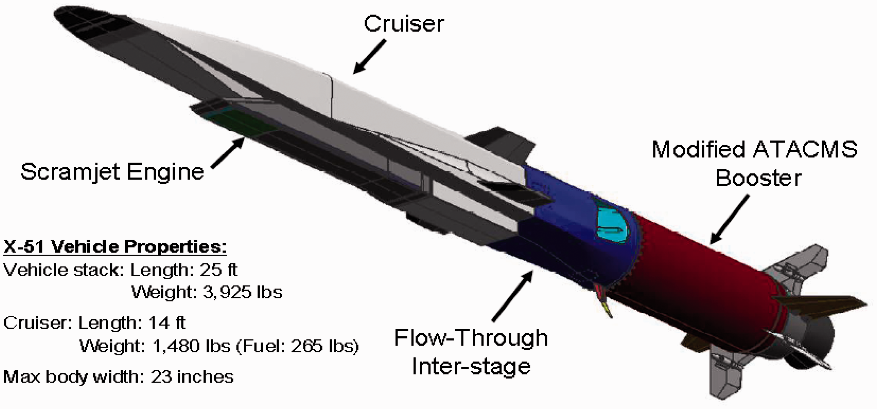
Structure of the X-51A vehicle. 18
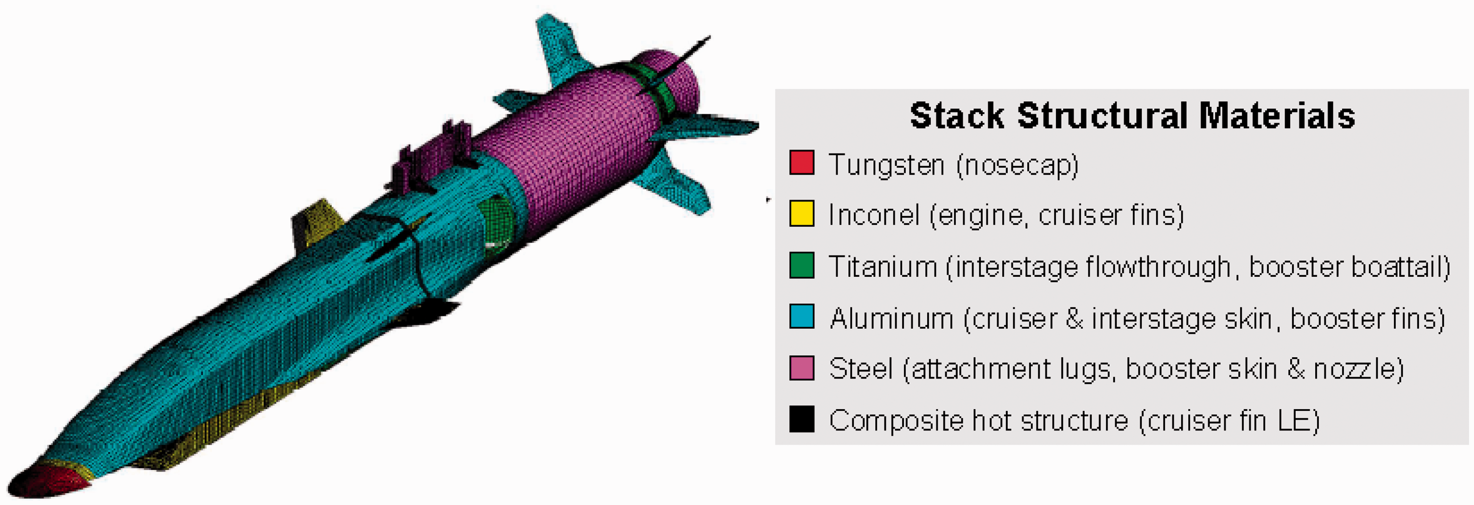
Structural materials of the X-51A vehicle. 18
Finite element modelling
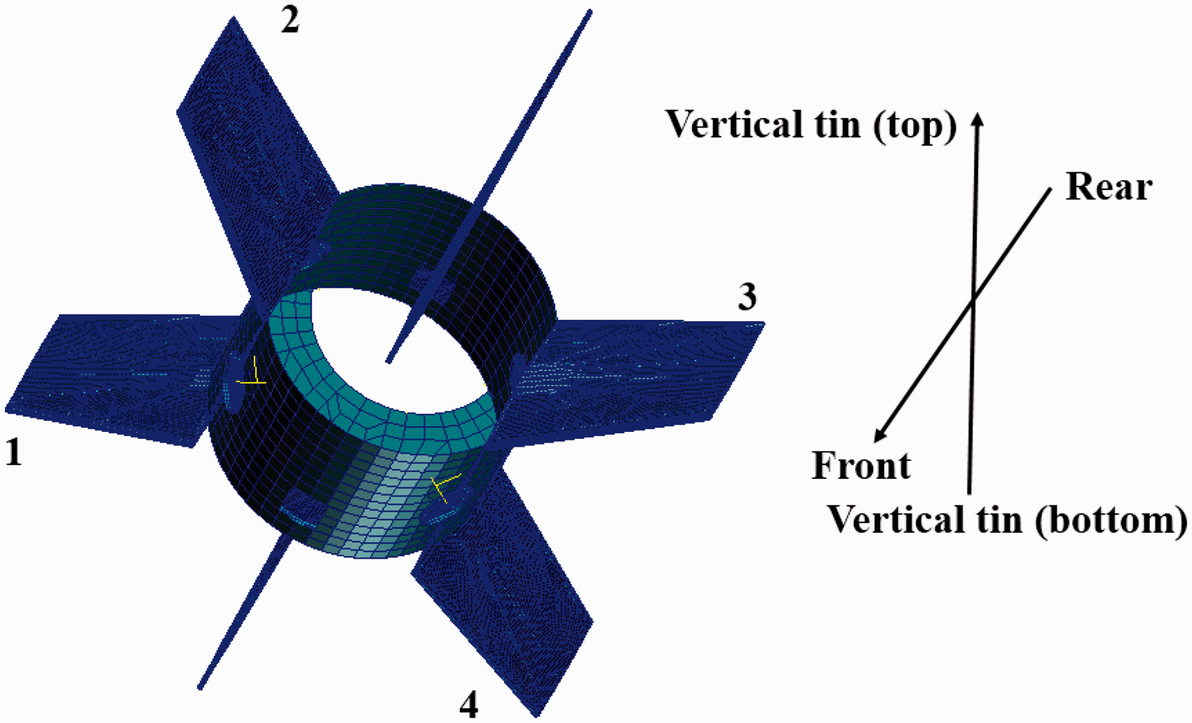
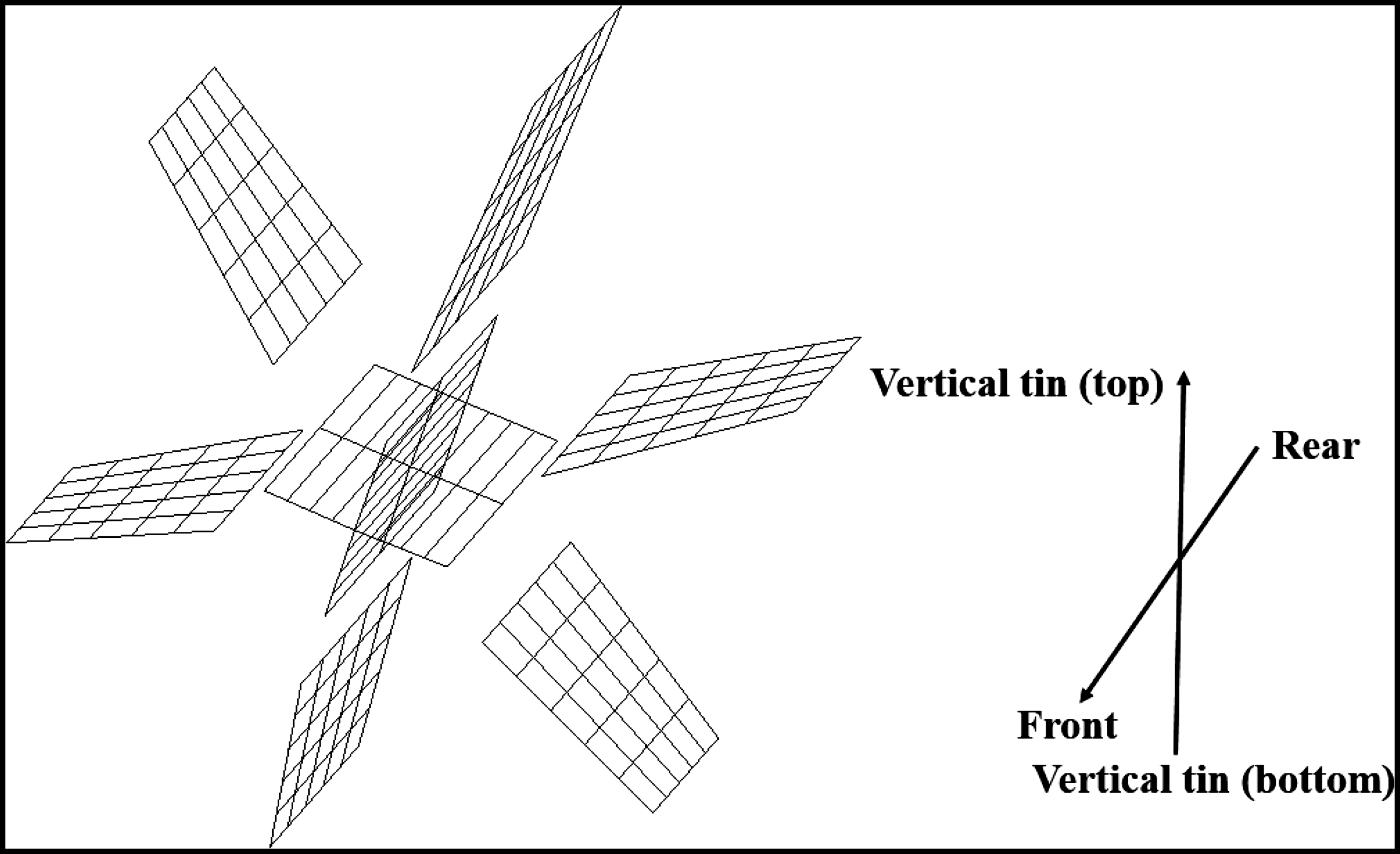
The present all-movable rudder system included a tail cabin, six all-movable rudders, six rudder shafts which connect the cabin and rudders. At the beginning, the coordinate system should be defined. The whole aircraft coordinate system used global coordinate system. According to the definition of aircraft coordinate system, the view of coordinate system is shown in Figure 3. The detailed definition was the origin point O was the vertex of the aircraft leading edge; the X axis was parallel with the longitudinal direction and the positive direction was pointed to the rear of the aircraft; the Y axis was inside the longitudinal symmetrical plane of the aircraft and perpendicular to the X axis, the positive direction was pointed to the top of the aircraft; and the Z axis was perpendicular to the OXY plane and pointed to the outside of the page.
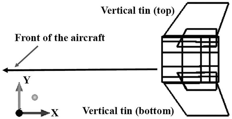
Definition of the coordinate system for the global aircraft.
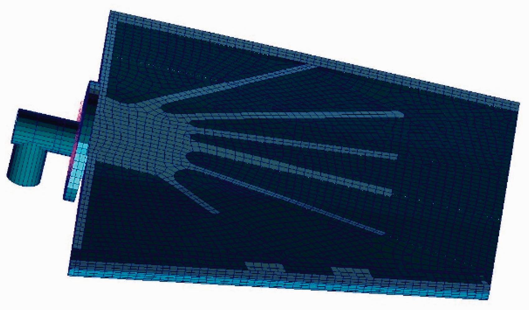
Material characteristic was selected as shown in Figure 2. In order to decrease the local mode influence, the present modelling mainly used two-dimensional (2D) element to form three-dimensional (3D) structural model. The tail cabin was modelled with 2D shell and beam elements, as shown in Figure 4. The rudders were modelled with both 2D shell and beam elements and 3D entity elements, as shown in Figures 5 and 6: the skin was modelled with shell elements; high temperature leading edge, internal skeleton and flange were modelled with entity elements; rotation shaft was modelled with beam elements and the operating stiffness of rudder control actuator was modelled through spring element in the X direction. In order to present clearly, the two vertical rudders, which were perpendicular to XOZ plane, were called vertical tin (top and bottom). The other four rudders were numbered from 1 to 4, as shown in Figure 5.
FEM modelling of the tail cabin of the system. FEM: Finite Element Method.
FEM modelling of the rudder system. FEM: Finite Element Method.
FEM modelling of a detailed rudder including its rotation part. FEM: Finite Element Method.
Modal analysis
Numerical analysis
Towards modal analysis, the structural undamped free vibration equation was written as


Solving the root of the characteristic equation, the value of
Mode computation.
GVT: ground vibration testing.
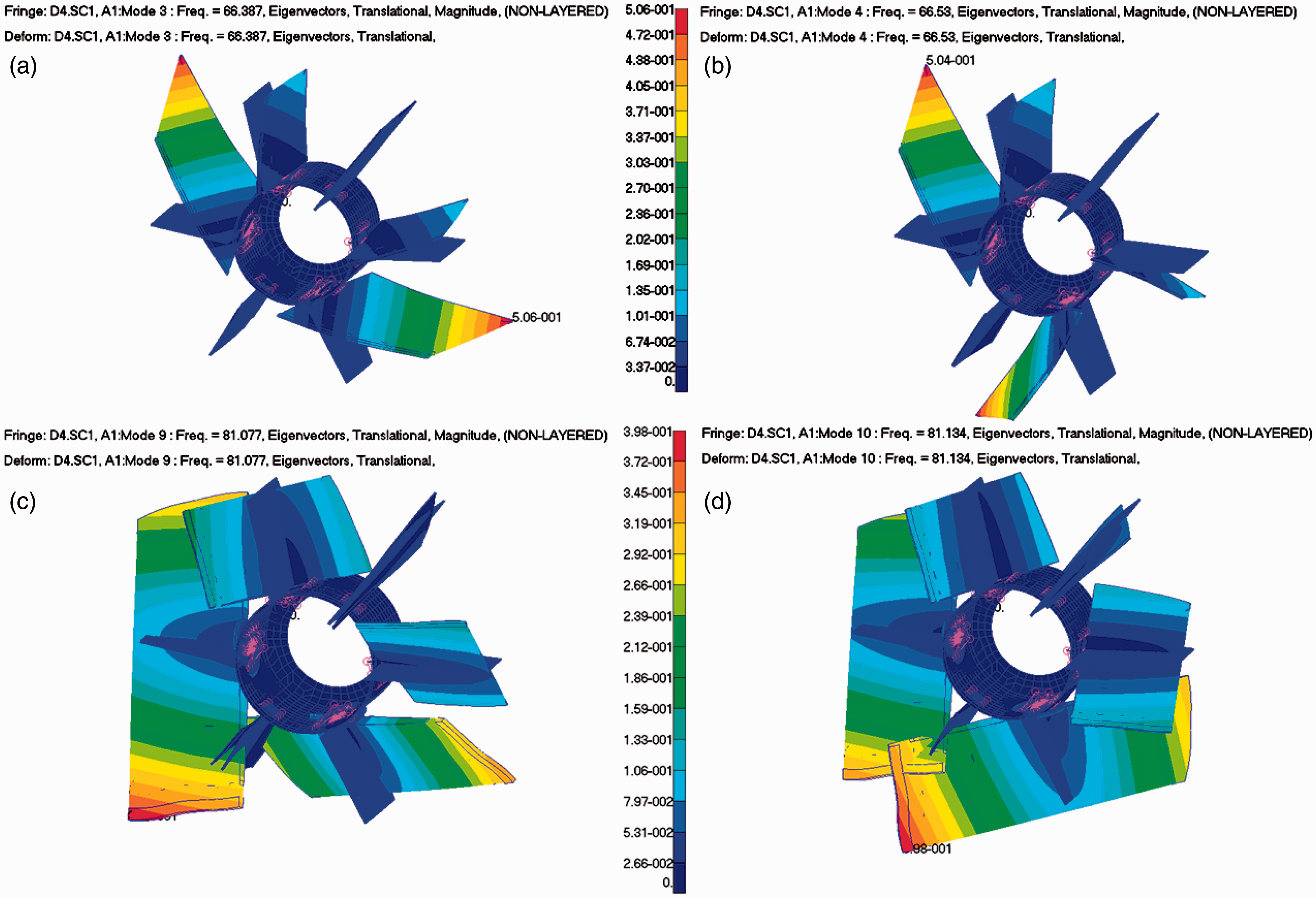
Modes of the rudders 1 and 4. ((a) and (b): the first symmetric and antisymmetric bending, respectively; (c) and (d): the first symmetric and antisymmetric torsion, respectively).
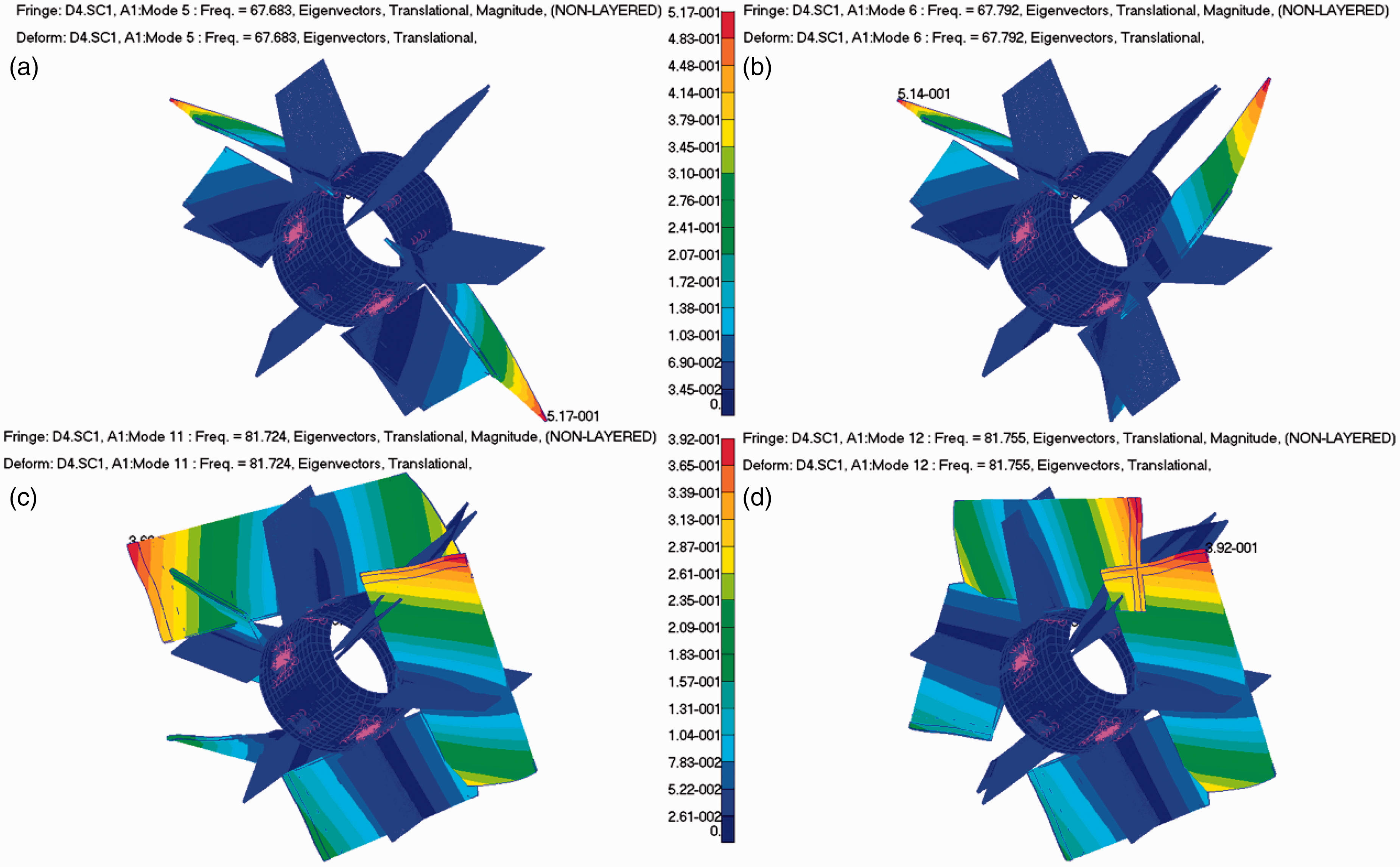
Modes of the rudders 2 and 3. ((a) and (b): the first symmetric and antisymmetric bending, respectively; (c) and (d): the first symmetric and antisymmetric torsion, respectively).
Ground vibration testing (GVT)
The experiments employed two rudders due to the symmetry, as shown in Figure 9.
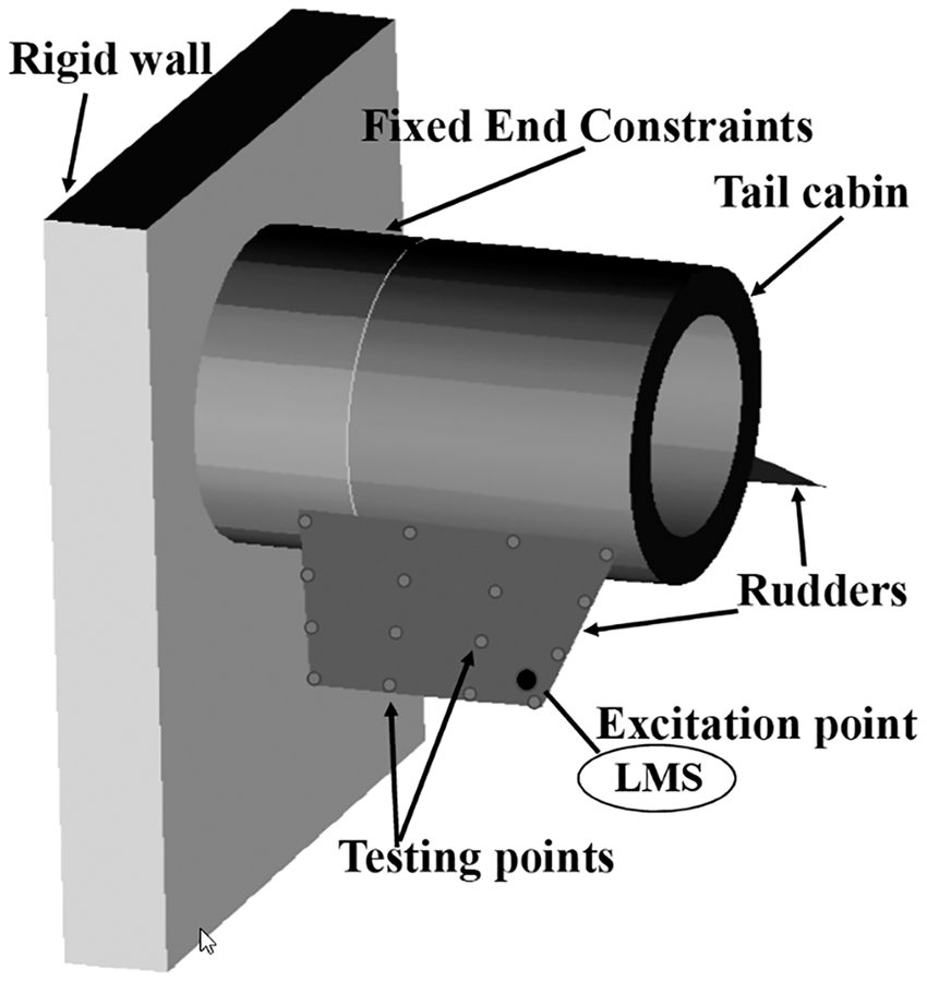
Arrangement of ground vibration testing.

LMS 32 Channel GVT system.GVT: ground vibration testing.
Self-owned LMS 32 channel GVT system (i.e. a product of Siemens business) which included LMS SCADAS input module and Test.Lab desktop software was used to complete GVT experiments, as shown in Figure 10. A group of PCB modal array acceleration transducers 333B30 (i.e. a product of PCB Piezotronics, Inc) were arranged on the rudders. This testing system was generally recognized as an effective tool for GVT experiments.19,20
The present experiment employed Random Multiple-Input Multiple-Output (MIMO) method to complete GVT process. Random MIMO method was chosen in this paper because it had many useful advantages: 21 it can employ multiple parallel measurement functions, it can use fixed or user-defined display layouts, it can provide detailed overload information and it can use level indicators.
The experiment detail was presented as follows: Excitation position: excitation point was located in the middle of the wingtip when measuring bending modes; excitation point is located in the middle of the trailing edge of the rudder when measuring torsional modes.
Arrangement of measuring points: both four rows in chord direction and spanwise direction, a total of 16 measuring points.
The experimental situation can be seen in Figure 9.
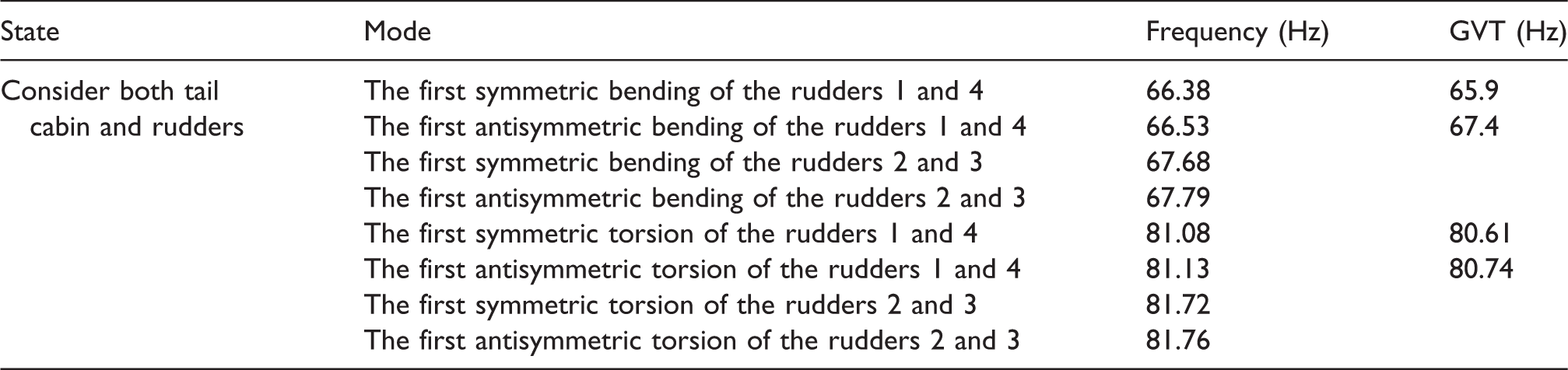
The GVT results can be found in Table 1. The experimental values agreed very well with the computed values. Figures 11 and 12 presented the experimental modes based on the testing system.
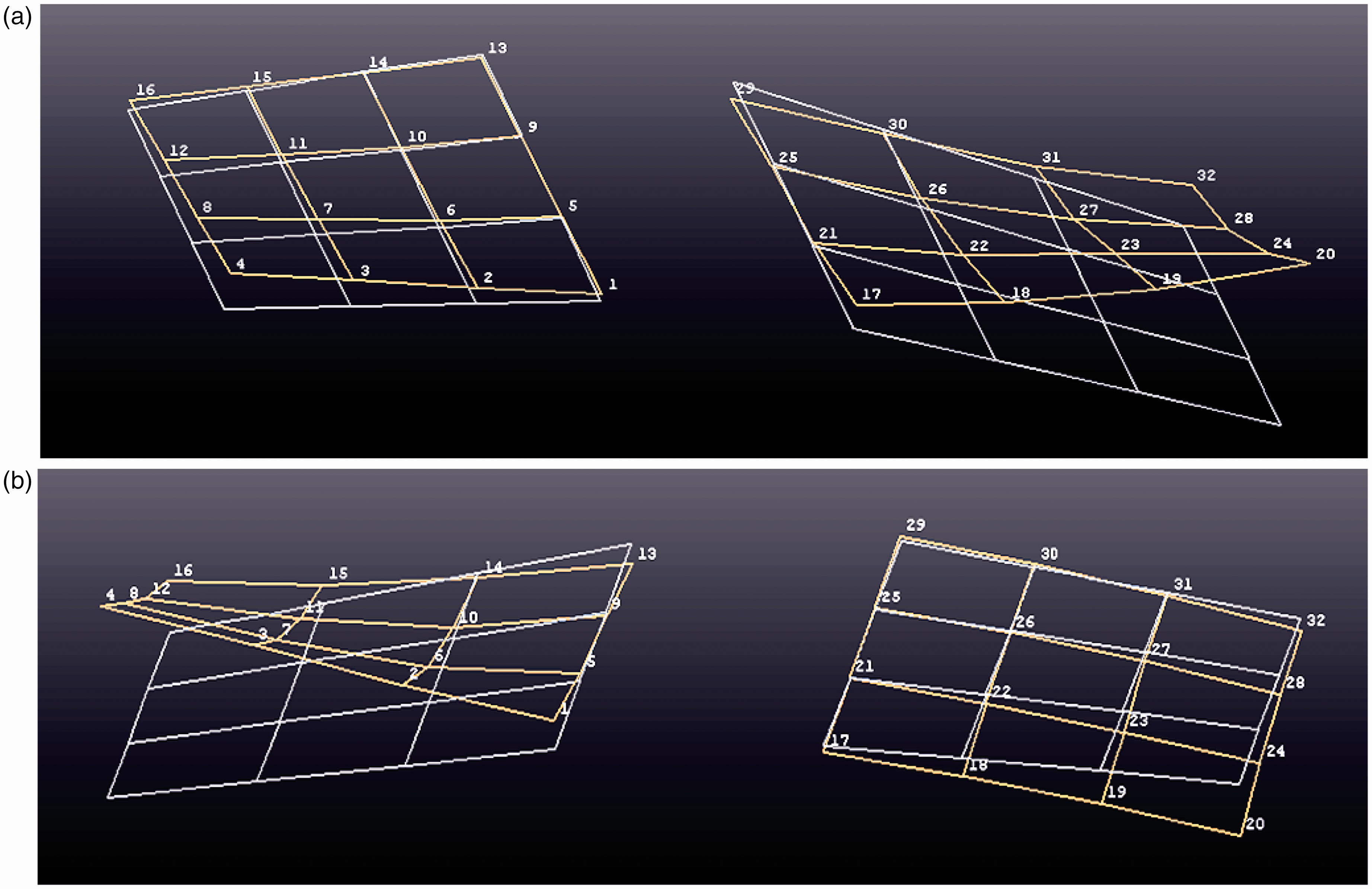
Experimental modes of the first symmetric (a) and antisymmetric (b) bending (i.e. yellow wireframe represents mode of vibration while white wireframe represents the initial model).
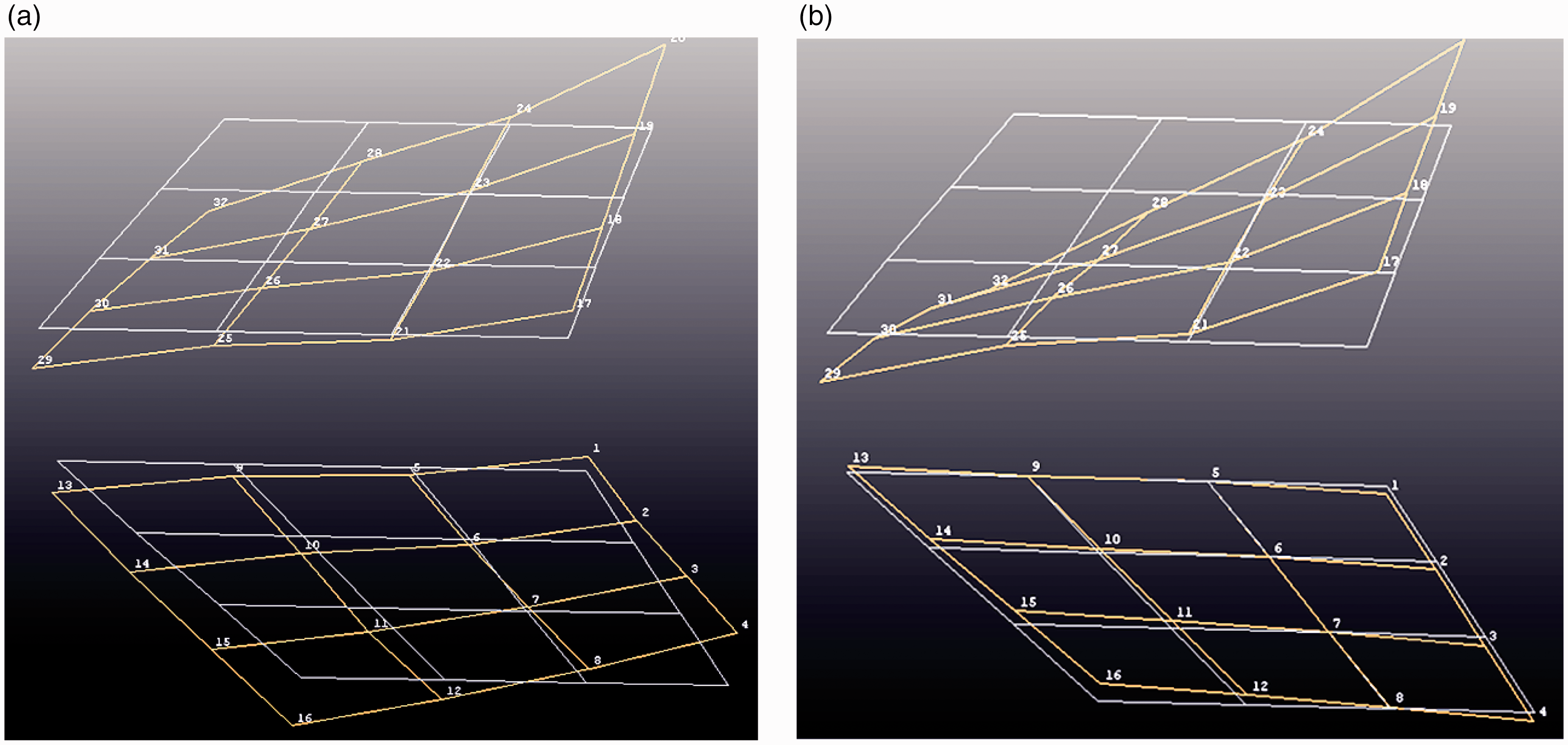
Experimental modes of the first symmetric (a) and antisymmetric (b) torsion (i.e. yellow wireframe represents mode of vibration while white wireframe represents the initial model).
Discussion on modal analysis
It was seen from the computation that the first symmetric and antisymmetric bending frequencies of the rudders 1 and 4 were closed. These results were also found for torsion frequency. The same phenomenon can also be observed for the rudders 2 and 3. It proposed the present all-movable rudder system possessed complex dynamic characteristics. Without accurate FEM modelling, dynamic analysis will be challenging. The present FEM modelling strategy was effective to capture useful modes of such complex rudder system.
From the numerical analysis and GVT results, it can be seen that obvious coupling modes existed among the rudders. So when investigating dynamic characteristic of such complex all-movable rudder system of hypersonic aircraft, coupling vibration should be considered.
Not only numerical evaluation but also GVT results revealed that the existence of closed modes of the rudders, which were similar to the values of modal analysis. It can be concluded that the present FEM model method was effective for modal analysis. And the related model can be used for the rear aeroelastic analysis.
Flutter analysis
Aeroelastic response of flight vehicle is a result of the mutual interaction of inertial and elastic structural forces, aerodynamic forces induced by the static or dynamic deformation of the structure, and external disturbance forces. The equation of motion of the aeroelastic system in terms of discrete system can be derived based on the equilibrium condition of these forces

In equation (4), the terms 
The generation of
Doublet lattice method 22 was effective for engineering flutter analysis, and the main code had been involved in the commercial software ZAERO. The related plane aerodynamic grid for the present system including a tail cabin and six all-movable rudders is shown in Figure 13. The computational parameters were Mach number was set to 3 and 4; flight height was varied from 0 to 12 km.
Plane aerodynamic grid for the doublet lattice method.
When the X-51A Vehicle flights with a fixed Mach number, the vehicle will employ a corresponding local flight speed. It was obvious that this local speed was changing due to the flight height, as shown in Figures 14 and 15. With doublet lattice method and the values of flight height, the relationship between flutter boundary and local speed can be computed.
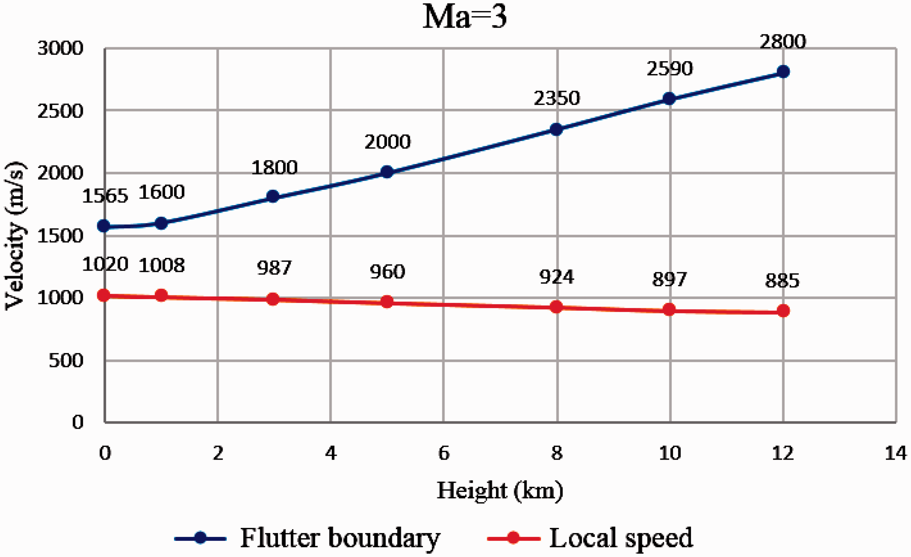
Flutter boundary of the present system at Mach 3.
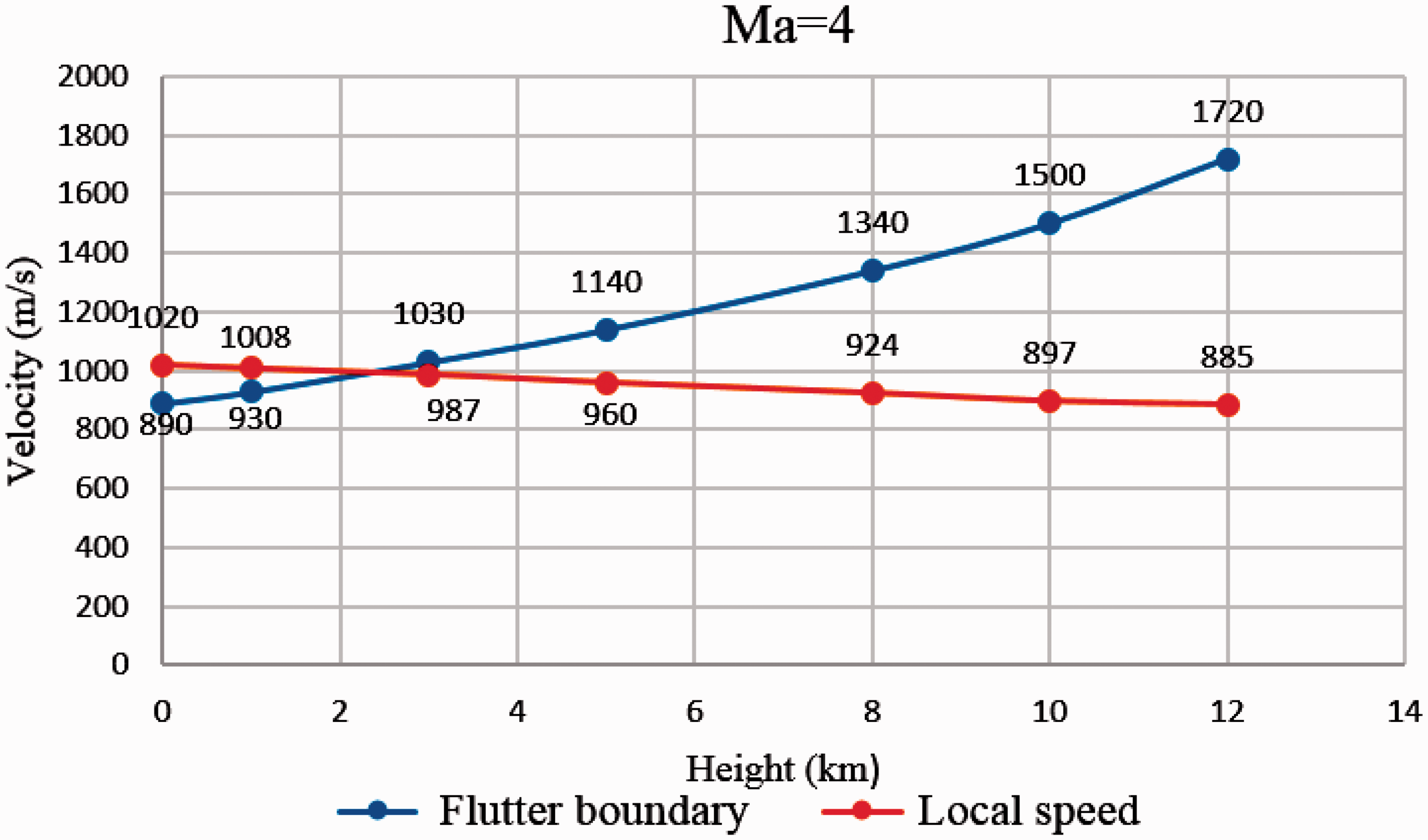
Flutter boundary of the present system at Mach 4.
Flutter boundary of the present rudder system is shown in Figures 14 and 15. It was seen that the flutter critical velocity increased with the flight height. When Mach number was set to 3, the local velocity curve did not cross the flutter velocity curve, so it meant that there was no flutter phenomenon. When Mach number was set to 4, the local velocity curve crossed the flutter velocity curve when the height value was about 2.3 km, so it meant that there was no flutter phenomenon after the flight height was larger than 2.3 km. If it wants to avoid flutter phenomenon, the X-51A vehicle must decrease the flight Mach number when the flight height is lower than 2.3 km.
Conclusion
A complex all-movable rudder system of the X-51A hypersonic aircraft was investigated in this paper. An effective FEM modelling method of this system was proposed by mainly using 2D elements. The numerical evaluation of modal analysis was very similar to the experimental results provided by GVT. After believable modal analysis results were established, flutter analysis of the present all-movable rudder system was taken, and the flutter boundary was found in order to suggest the dynamic stability of the present system. It was found from the results that there were strong coupling modes among every rudder of the complex system.
It can be concluded from the present analysis that an effective FEM model is necessary for dynamic analysis of a complex aircraft system, but 3D detailed element-based model is not absolute; especially for low frequency range, 2D equivalent element-based model can avoid local mode influence and provide effective mode evaluation for further aeroelastic analysis; GVT is necessary for the establishment of the dynamic modelling of a complex aircraft system; it can also provide a significant feedback for FEM modelling efficiency.
This paper presented aerodynamic characteristic of the complex all-movable rudder system for the X-51A vehicle; it has application potential for the other investigations similar to the X-51A vehicle.
Footnotes
Declaration of conflicting interests
The author(s) declared no potential conflicts of interest with respect to the research, authorship, and/or publication of this article.
Funding
The author(s) disclosed receipt of the following financial support for the research, authorship, and/or publication of this article: The work was financially supported by the National Program on Key Research Project (Funding Code 2016YFB0200705) and the Fundamental Research Funds for the Central Universities (Funding Code DUT162D(G)03 & DUT16RC(4)29).