
Abstract
With the increasingly emerging traffic intersection form of high-speed railways passing underneath integrated transport terminals, the ground vibration induced by trains running on underground high-speed railways has attracted extensive attention. In combination with the engineering example of a high-speed railway in construction passing underneath an airport, the wheel-drop impact test in the high-speed railway tunnel was designed to obtain the vibration characteristics of surrounding soil. The vehicle-track-tunnel-ground semi-analytical three-dimensional model was established to determine the initial dynamic load condition of the vehicle loads. The amplitude-frequency characteristic and transmission law of the ground vibration induced by trains running on underground high-speed railways were predicted and analyzed. The influences of different operation conditions, track parameters, and tunnel burial depths were compared. The research results show that the ground vibration obtained through the wheel-drop test is greatly attenuated within 10 m from the track centerline, with an attenuation rate up to 70%. The vertical vibration amplitude is obviously larger than that of the other two directions. The lateral ground vibration amplitude is the smallest with the slowest vibration attenuation speed. When the high-speed train passes through at the speed of 350 km/h, the vertical and lateral vibration levels of the ground surface within 80 m range are 20∼80 dB and 43∼72 dB, respectively. The maximum attenuation coefficient of Z-vibration level reaches 0.276 dB/m. For each increase of 50 km/h of the train speed, the Z-vibration level of the ground increases by about 2 dB. The smaller fastener stiffness leads to the greater ground vibration within 20∼50 Hz. The ground vibration level is positively correlated with the fastener stiffness above 79 Hz. When the burial depth of the tunnel is greater than 14 m, the burial depth of the tunnel has little effect on the change of the Z-vibration level of the ground.
Introduction
Depending on its advantages such as high running speed, sound safety performance and convenience, the high-speed railway has developed rapidly in recent years. Considering the needs of intercity connectivity and transfer convenience, more and more high-speed railways are laid underneath the main urban areas in China, such as the Futian section of the Guangzhou–Shenzhen–Hong Kong express rail link and the Shenzhen section of the Guangzhou–Shenzhen intercity railway. Although the underground high-speed railway has obvious advantages in improving the urban traffic network, the ground vibration caused by the operation of the high-speed trains in the tunnel may affect buildings and precision instruments along the railway line.1,2 In China, multiple high-speed railways passing through the urban areas have to reduce the operation speed on account of hardly mastering the ground vibration characteristics and transmission laws , 3 such as the into-city section of Beijing–Zhangjiakou high-speed railway, the Shijiazhuang section of Beijing–Guangzhou high-speed railway, the Qingdao section of Jinan–Qingdao high-speed railway which limit the operation to 200 km/h or below. Also at the vibration-sensitive sections the actual operation speed are all less than the design speed, thus seriously affecting the efficiency of the high-speed railway. The transmission of the ground vibration under the action of the moving train is a three-dimensional issue that involves the geometric irregularities of the track, the sub-rail foundation structure and the rock and soil mass. 3 It is of great theoretical and practical significance for the laying and structural design of new high-speed railway lines to adopt a reliable prediction method for evaluating the ground vibration induced by trains running on underground high-speed railways.
The methods of numerical simulation and field measurement are mostly used in the prediction of the underground train-induced ground vibration. Jin Qiyun 4 et al. and He Chao 5 et al. used 2.5D calculation method and coupled finite element-boundary element method to analyze the environmental vibration induced by the train running in the tunnel. Germonpre 6 et al. applied the periodic method with the finite element-boundary element coupling method to analyze the railway induced vibration, while Cui Gaohang 7 et al. and Costa 8 et al. applied the 2.5D calculation method with the finite element-infinite element coupling method. Yang Yongbin 9 et al. compared the responses of soil-tunnel systems to moving train loads using the two-dimensional and 2.5D finite/infinite element approaches. For the 2.5D approach, the two-dimensional profile with two in-plane DOFs and one out-of-plane DOF is used to simulate the three-dimensional response of the system, while the geometry and material of the tunnel-soil system is assumed to be uniform along the train operation direction. Yang Jianjin 10 et al. combined the analytical method with the finite element method to predict the train-induced vibration of a large-scale building constructed on subway tunnel. Sun Chenglong 11 studied the generation mechanism and transmission law of the ground vibration of high-speed railway underground line through the numerical simulation and field test. Xu Qingyuan 12 et al. compared the two-dimensional and the three-dimensional prediction models of ground vibrations induced by underground railways for a direct fixation track and steel spring floating slab track.
Since the numerical methods applied above for the analysis of ground vibration are generally based on simplifying assumptions such as uniform distribution of soil layers along the longitudinal direction, it is difficult for such methods to simulate all the inherent complex properties and uncertainties of the dynamic behavior of soil. The measured vibration data obtained from the field tests can reflect the ground vibration characteristics most realistically and avoid the disturbance of the assumptions in simulation models on the evaluation results. Xiao Guiyuan 13 et al. conducted field test on the characteristics of the vibration of building structures built jointly with the metro line caused by Shanghai Metro Line 10, and obtained the transmission law and frequency distribution characteristics of the ground vibration. Sheng Tao 14 et al. carried out field monitoring on the ground vibration induced by a metro tunnel in Shanghai under soft soil site conditions, and analyzed the three-directional vibration of the metro tunnel, adjacent free field and adjacent buildings. Zheng Guochen 15 et al. measured the ground vibration under the condition of metro and heavy-duty train passing jointly and compared it with the simulation results. Liu Weining 16 et al. conducted deep-hole excitation test to predict and analyze the impact of the ground vibration induced by metro trains. Liu Tao 17 took the underpass section put into operation of the intercity railway from Zhengzhou East Railway Station to the airport as an example, and analyzed the ground surface vibration caused by train operation according to actual measurements. Connolly18,19 et al. and Marshall 20 et al. conducted field measurement and frequency-domain analysis for the ground vibration caused by the operation of high-speed railways in Berlin and across Europe. Most of existing studies focus on field measurements of high-speed railways in operation, or predictions based on low-speed metro tests. The research from the in-operation underground high-speed railway and low-speed metro tests show that the ground vibration due to the underground high-speed railway is more intensive than the metro line above 80 Hz. 3 However, there hasn’t been found the study on the ground vibration caused by underground high-speed railways based on the test method at the beginning of construction.
In this paper, an in-situ-test-based ground vibration prediction method for underground high-speed railways is proposed. The amplitude-frequency characteristic and transmission law of the ground vibration induced by trains running on the underground high-speed railway are analyzed based on an engineering example of the high-speed railway under construction passing underneath an airport site. The influence characteristics of different operation conditions and track parameters are compared. The reasonable burial depth of the tunnel is also discussed, thus providing theoretical basis and measured data for relevant theoretical analysis and engineering application.
Prediction method
Ground vibration prediction is to study the quantitative determination of the energy intensity for the vibration transmitted to the vibrated object when the transmission chain consisting of the vibration source, transmission path, and vibrated object changes. For the prediction method, in terms of the vibration source system, the vibration transmission system and the vibration receiving system, the impact load spectrum of the vibration source is obtained by the wheel-drop impact test. And the transfer mobility describing the relationship between the impact force and the ground vibration acceleration is solved according to the recorded ground acceleration spectrum. The transfer mobility is a function of the vibration frequency and the distance from the vibration source, reflecting the comprehensive influence of the vibration wave transmission medium, wave types, and all transmission paths. The excitation generated by the high-speed trains acting on the tunnel base is regarded as the combination of a series of single-point excitations. The ground vibration response caused is described by the line source transfer mobility which is solved from the point source transfer mobility. As the influence of the underground passing train could not be measured at the beginning of construction, the method of numerical simulation is applied to solve the force density level that characterizes the wheel-rail excitation effect. The framework of the prediction methodology is shown in Figure 1. Framework of prediction methodology.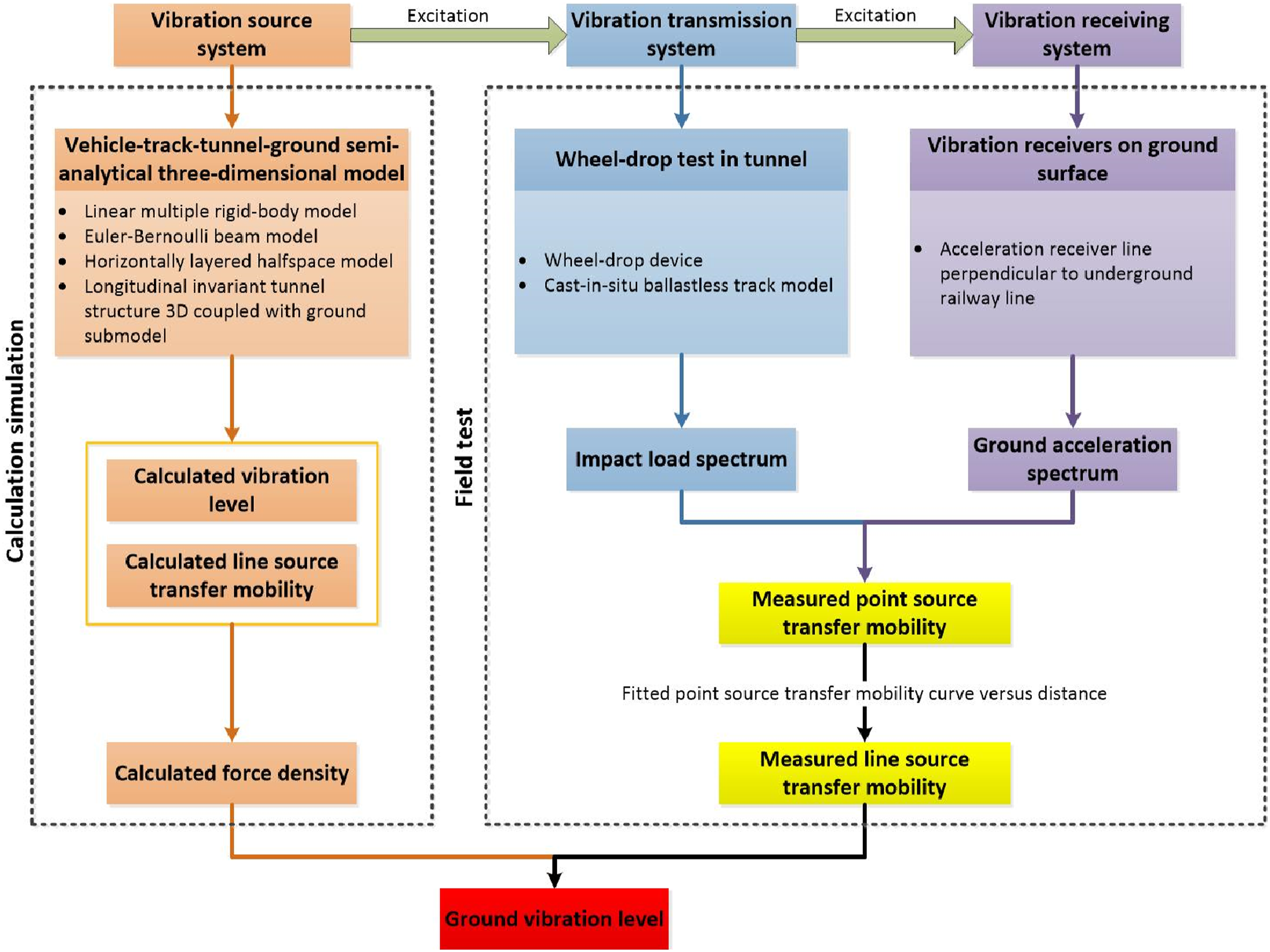
In-situ wheel-drop impact test
Test method
The load exciting the vibration of the track-tunnel-ground system is provided by means of the wheel-drop impact test. The wheel-drop impact test method21,22 is a common method to study the dynamic characteristics of the vibration system. The running flat wheel is the main factor in leading to the wheel-rail dynamic behavior. Under the high-speed condition, the flat wheel leaves the rail surface, floats upward in air and drops downward with wheel rotating, finally impacts the rail. When the train speed is equal to the critical speed at which the wheel leaves the rail, the vertical impact speed reaches to the maximum. The vertical maximum impact speed is proportional to the flat length, and the wheel-drop height is the function of the flat length, as shown in equation (1). With consideration of the random irregularity on rail surface, the wheel-drop height is given for the impact speed at which the energy of the dropping wheelset is equal to the standard deviation of the energy for the running train, as shown in equation (2)
23


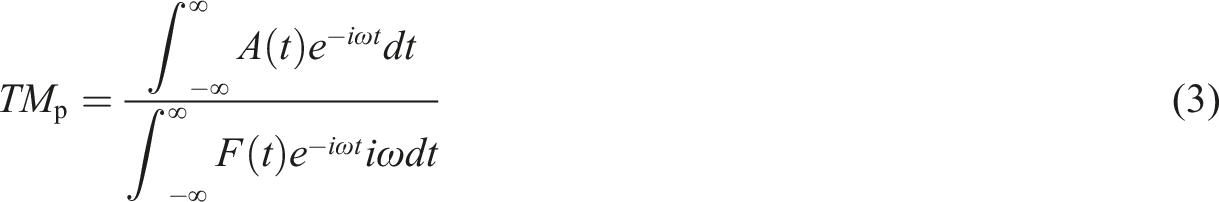
A specific wheel-drop device is applied to freely drop the wheelset from the chosen height to act the impact load on the track in order to excite the vibration of the track structure, tunnel foundation, and surrounding soil. The dropping wheelset is connected to the electric pushrod which is used to adjust the horizontal position of the dropping wheelset. The dropping height of the wheelset is adjusted by the attraction of the electromagnet lifted by the windlass. The operations of the main components in the wheel-drop device mentioned above except the dropping wheelset are all connected to the control platform. After the wheel-drop device is lifted to a certain height, the wheelset alignment, lifting, measuring, and wheel-drop height review are performed in sequence. The point source transfer mobility
Test outline
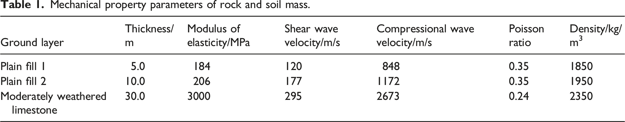
Mechanical property parameters of rock and soil mass.
Considering that the track has not been paved in the high-speed railway tunnel, a full-size model of CRTS I bi-block ballastless track is casted inside the tunnel, which is composed of rails, fasteners, bi-block sleepers, and track slab. The length, width, and height of the track slab model are 4.8 m, 2.8 m, and 0.255 m, respectively, and the rails are fixed on bi-block sleepers by WJ-8 fasteners. In order to reduce the influence of boundary conditions, the wheel-drop position is set in the middle of the track slab. CRH380A EMUs will run on the underpassing high-speed railway. According to the Regulations of Railway Technical Operation, assuming that the CRH380A EMU has 30 mm wheel tread flat, the wheel-drop height is calculated by equations (2) and (3) to be 30 mm. The weight of the wheelset is 1020 kg. The wheel-drop impact force is calculated by measuring the rail strain and interpolation with the calibrated wheel-drop impact force. The wheel-drop impact test device and the track structure model in the tunnel are shown in Figure 2. Wheel-drop impact test devices in tunnel.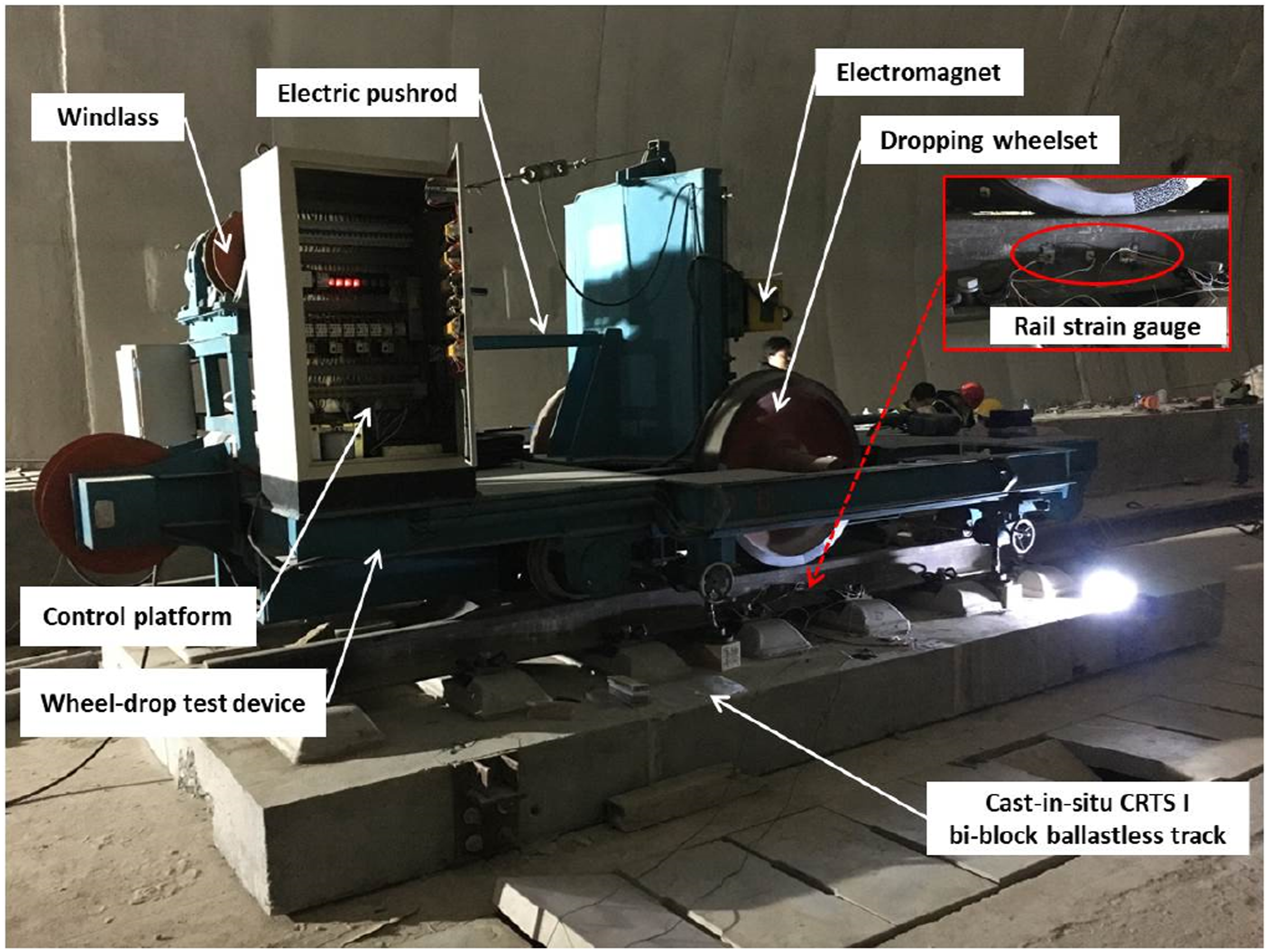
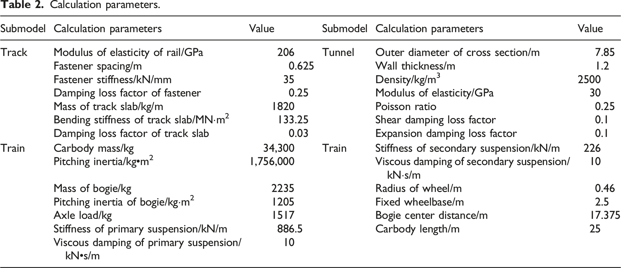
Ten measured points labeled T1∼T10 are arranged along the normal direction of the high-speed railway tunnel, with the wheel-drop center as the origin. The spacing between measured points is 5 m for T1∼T3 and 10 m for the other measured points. At each measured point, one vertical vibration pickup, one longitudinal vibration pickup (along the railway line direction) and one lateral vibration pickup (in the railway line normal direction) of 991B type are arranged and connected with the dynamic data acquisition system of INV3062A2 type, with a sampling frequency of 2000 Hz, as shown in Figure 3. Layout of measured points on ground surface.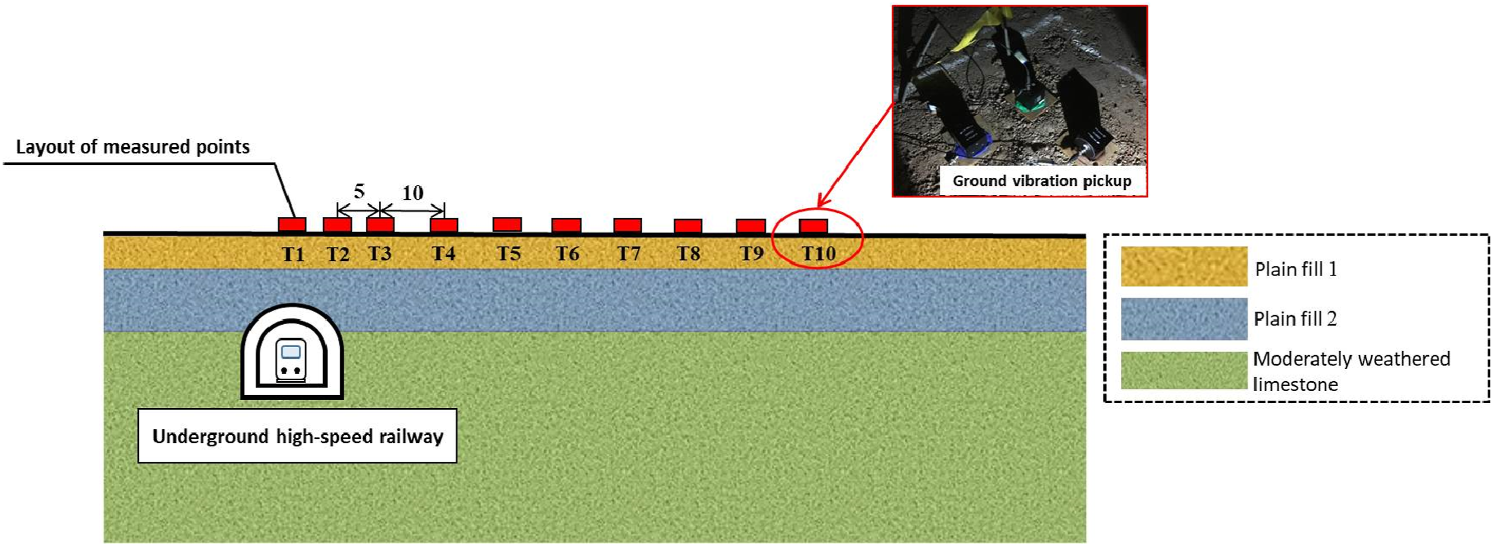
Test results
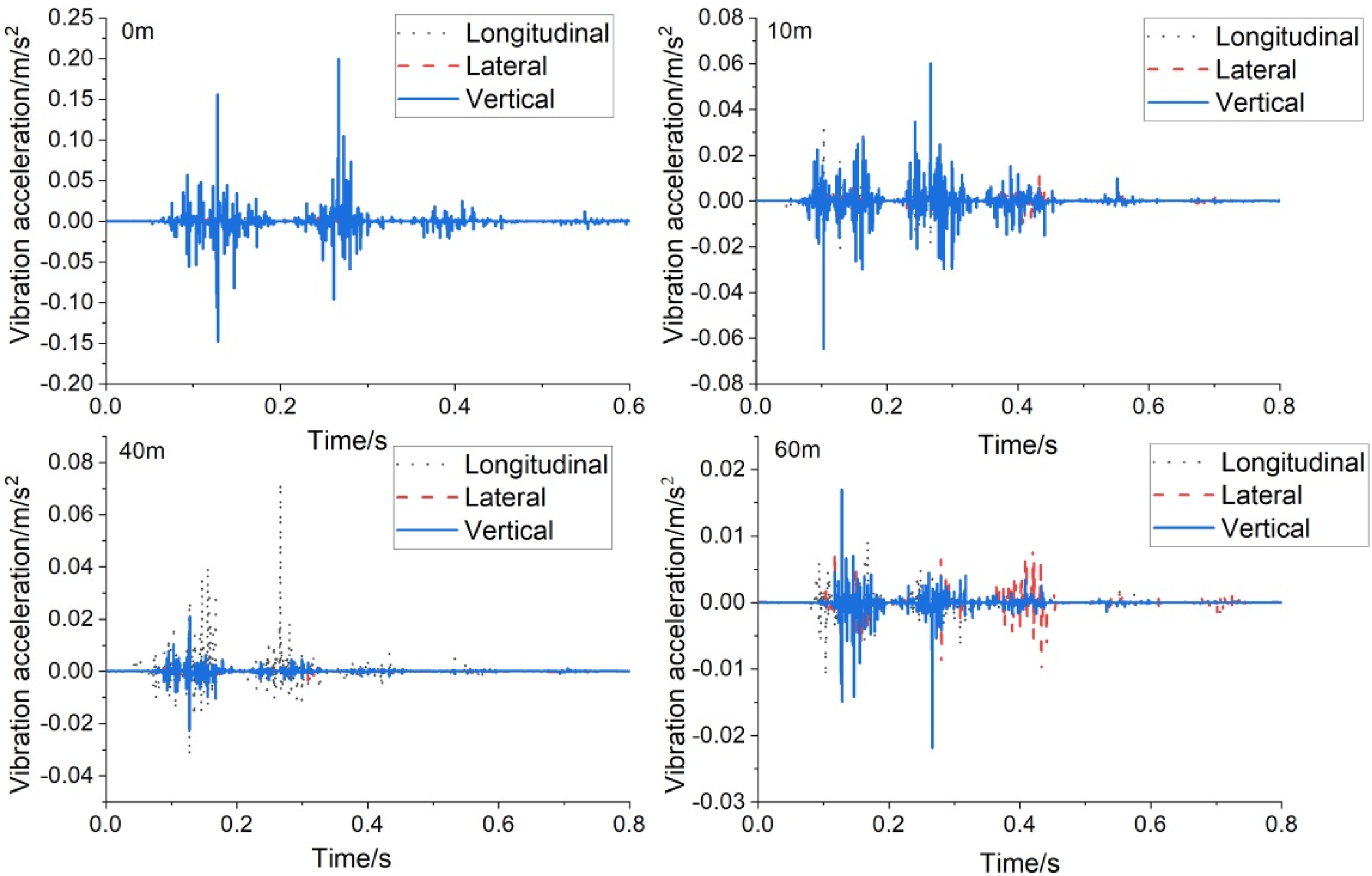
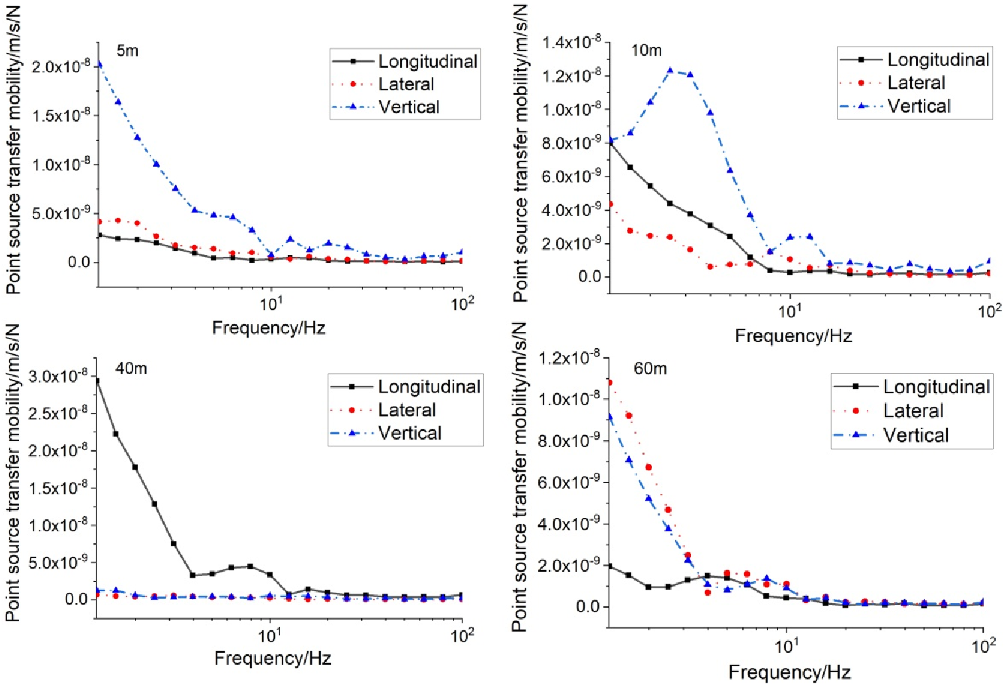
Under the given wheel-drop height, the wheel-drop impact force measured is as shown in Figure 4. Compared with the simulation results, the amplitude range and change trend of the impact force are basically the same, which proves that the test results are valid and can be used for the calculation of point source transfer mobility. Figures 5 and 6 show the ground vibration acceleration and point source transfer mobility extracted from representative measured points. The ground surface vibration attenuates gradually with the increase of the horizontal distance from the track centerline. The vertical vibration directly above the track is the most severe, with a peak vibration acceleration of 0.2 m/s2, but attenuates sharply within 10 m from the track centerline, with an attenuation rate up to 70%. The amplitude of the vertical vibration is significantly greater than that of the other two directions, but the longitudinal vibration is partially amplified at the distance of about 40 m, with an amplification rate of 6.4 times. The peak of the longitudinal vibration acceleration appears earliest, and the transmission speed for the longitudinal vibration is the fastest. The lateral vibration amplitude of the ground surface is the smallest, and the lateral vibration attenuation speed is the slowest. The main frequency of ground vibration is within 20 Hz. The three-directional vibration-sensitive frequencies of different measured points are different. For example, the vertical vibration-sensitive frequencies are 2.5 Hz, 8 Hz, 10 Hz, 13 Hz, and 20 Hz, while the longitudinal vibration-sensitive frequencies are 4 Hz and 8 Hz. The lateral vibration-sensitive frequencies are 5 Hz and 8 Hz. Wheel-drop impact force. Ground vibration acceleration. Point source transfer mobility of ground surface.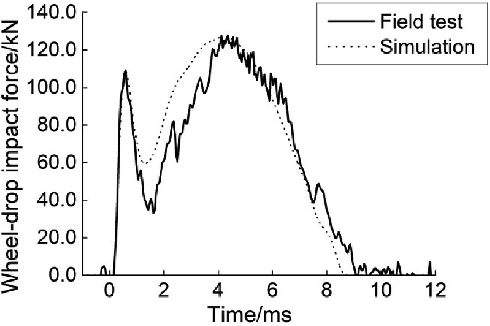
Vehicle-track-tunnel-ground semi-analytical three-dimensional model
Calculation model
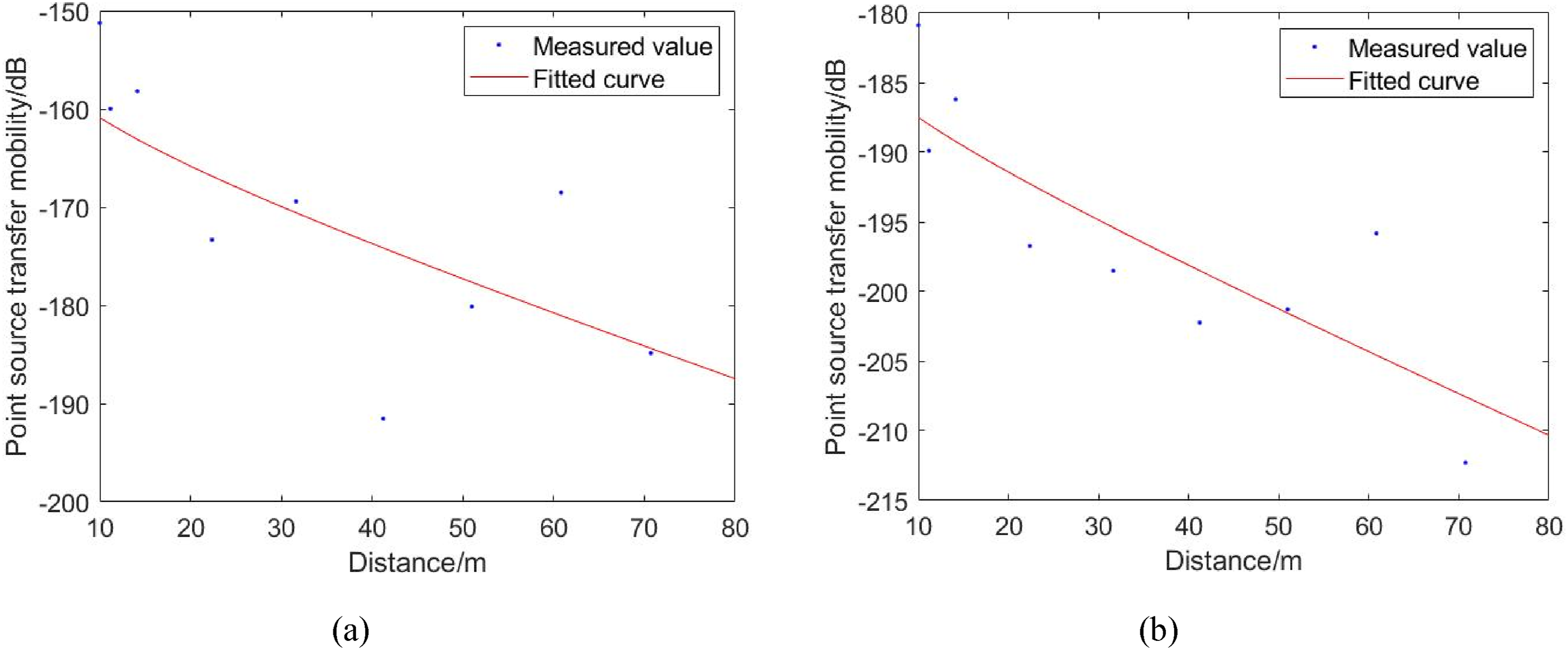
Calculation parameters.
Solution for force density level
The force density level reflects the level of excitation of the tunnel and surrounding rock and soil mass due to the wheel-rail interaction and the vibration of the track structure. It is solved by calculating the ground vibration level and the linear source transfer mobility,
28
as shown in equation (4). The calculation method in line source transfer mobility is shown in Figure 7, where the train excitation is described by the sequence of impact loads equally spaced within the train length, and is resolved through equation (5) based on the calculation of the point source transfer mobility at the fixed points of ground surface under impact load Diagram for calculation of line source transfer mobility.

Prediction results of ground vibration level
Measured line source transfer mobility
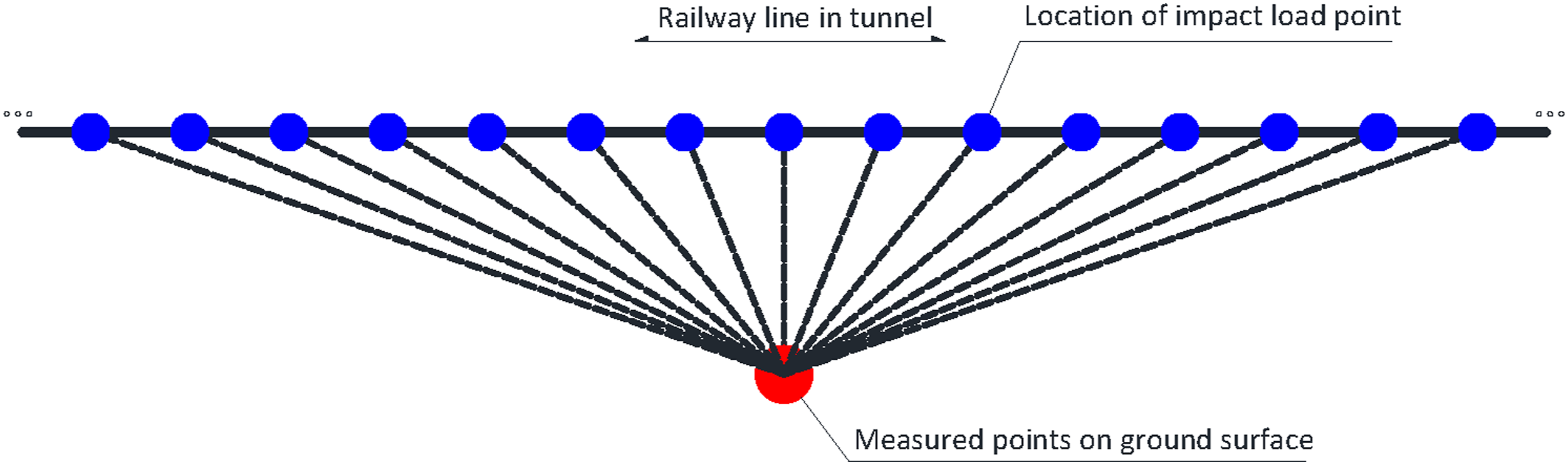
Ideally the line source transfer mobility required for the force density level are obtained by the measured point source transfer mobility for each impact load in tunnel as shown in Figure 8. However, the wheel-drop impact test devices are too heavy and complex to move in the tunnel and excite the track model at each impact load point in the field test. It is hard to measure the point source transfer mobility of the measured points on the ground surface under the assumption of multipoint excitation for fixed-point vibration pickup. Instead, the idea of single point excitation for multipoint vibration pickup is adopted. Based on the measured point source transfer mobility at the measured points T1∼T10 in 3.3, the functional relation of point source transfer mobility with distance is determined by curve fitting. By substituting the distance between measured point and impact load point in tunnel such as d
n
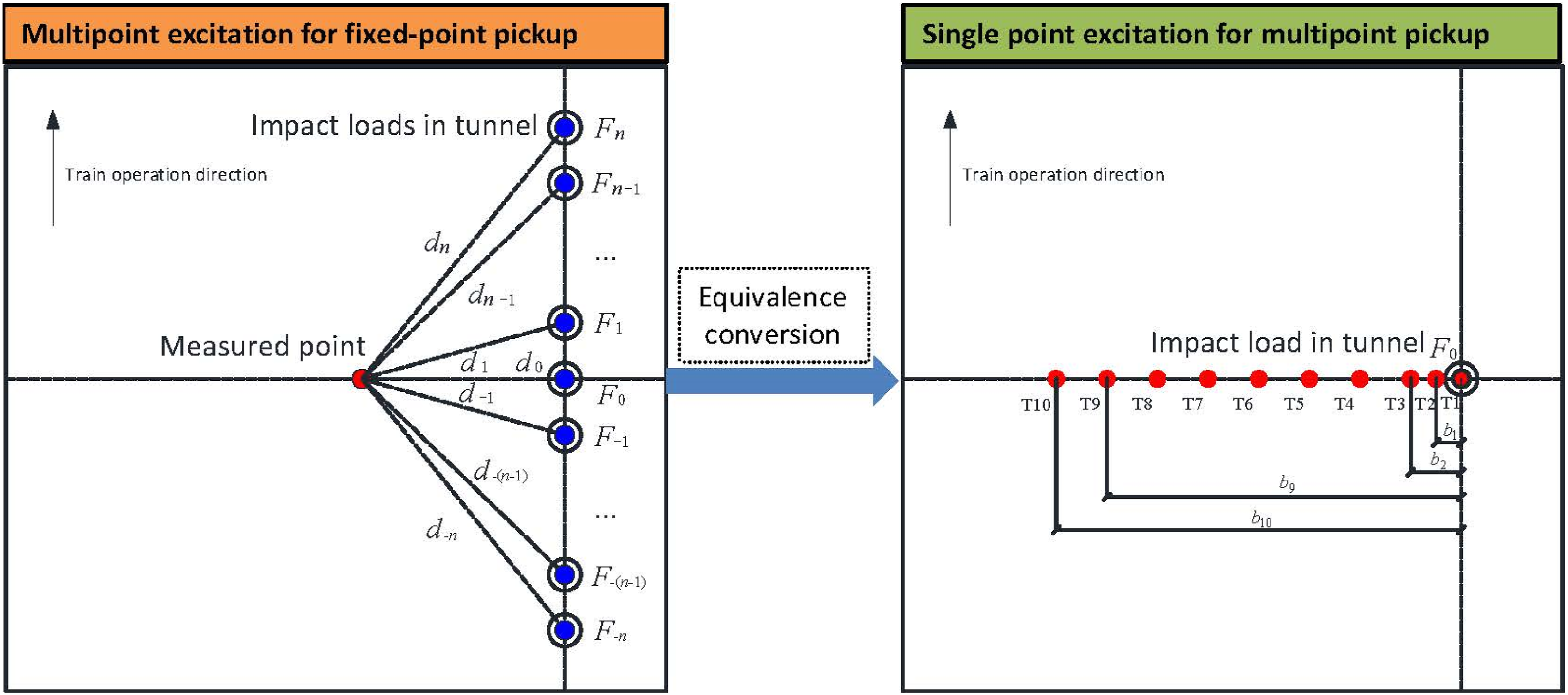
into the fitted curve, the measured point source transfer mobility is obtained. Due to the variation in the ground profile to a large extent, the test results show inconsistent variation. In order to better illuminate the mapping relation between the measured point source transfer mobility and the distance, the functional relation proposed by Thompson
1
is applied to the curve fitting, which is shown in equation (6). The corresponding fitted curves of selected center frequencies are shown in Figure 9. Diagram for calculation conversion. Functional relation of measured point source transfer mobility with distance. (a) 2.5 Hz, (b) 50 Hz.
Ground vibration level
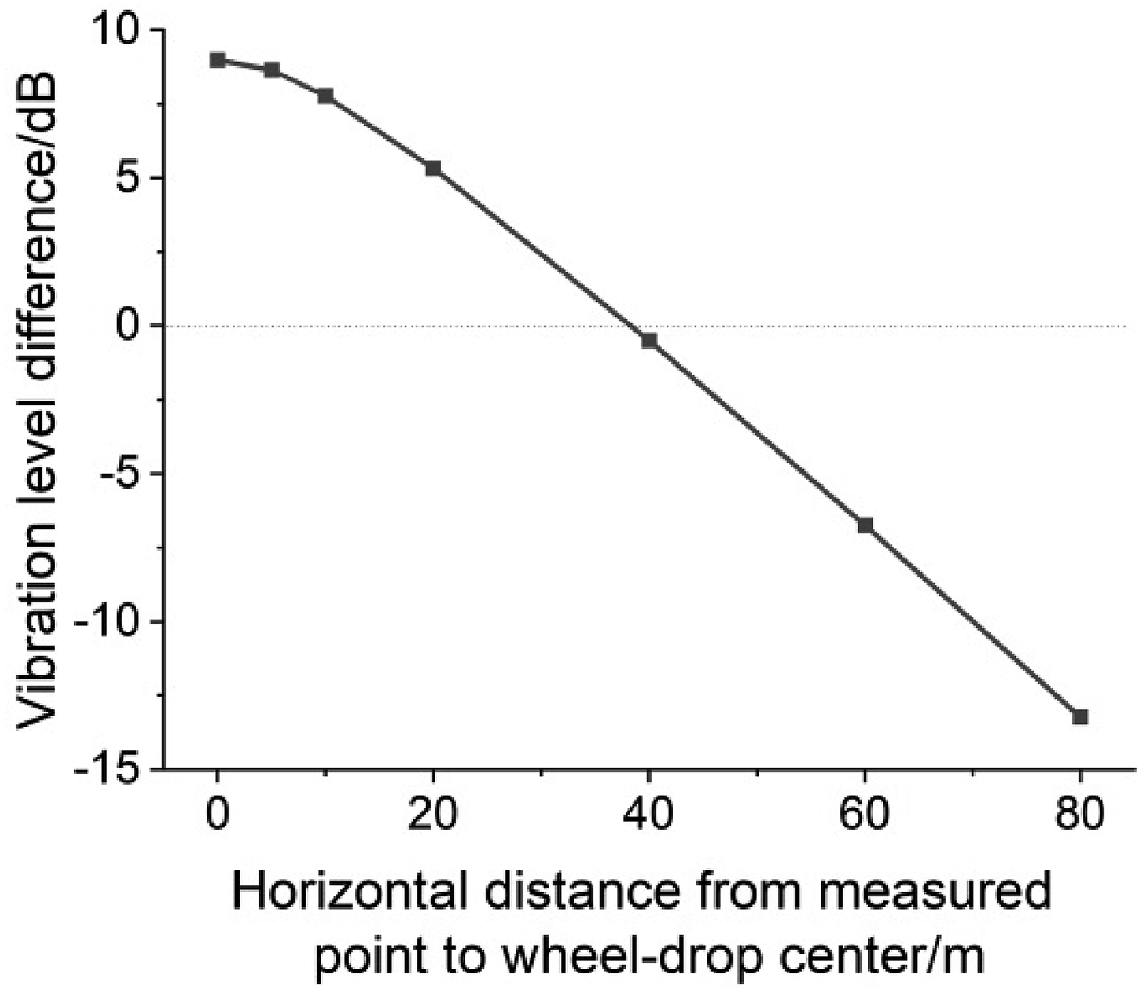
To analyze the distribution law of the ground vibration level in the frequency domain during the underpassing of the high-speed train at the speed of 350 km/h, equation (4) is adopted to calculate the vertical and lateral ground vibration levels at the measured points of different horizontal distances from the wheel-drop center, as shown in Figure 10. The vertical and lateral ground vibration levels in the range of 4∼80 Hz within the range of 80 m are 20∼80 dB and 43∼72 dB, respectively. The vertical vibration level within the range of 40 m is about 9 dB higher than the lateral average to the maximum, and the closer to the line, the greater the difference. The lateral vibration level beyond the range of 40 m is about 13 dB higher than the vertical average to the maximum, and the farther away from the line, the greater the difference, as shown in Figure 11. The frequencies for the peak vertical ground vibration are 4 Hz, 13 Hz, 25 Hz, 40 Hz, and 79 Hz. A peak also occurs at 63 Hz within the range of 5 m. The vertical vibration level varies greatly and uniformly with the horizontal distance. The frequency for the peak lateral ground vibration is the same as that for the vertical vibration, but the peak at 13 Hz and 63 Hz increases significantly beyond the range of 60 m, and the lateral surface vibration level is not sensitive to the distance. Ground vibration level. (a) Vertical (b) Lateral. Comparison of differences between vertical and lateral ground vibration levels.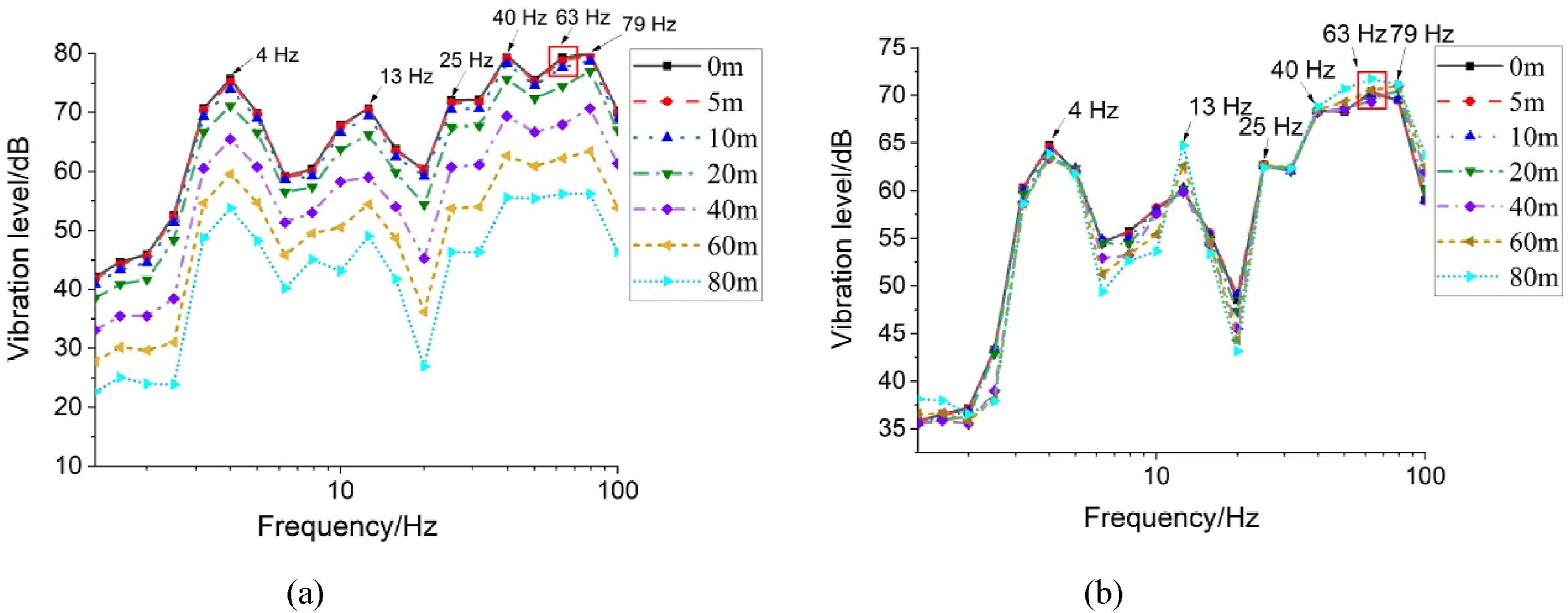

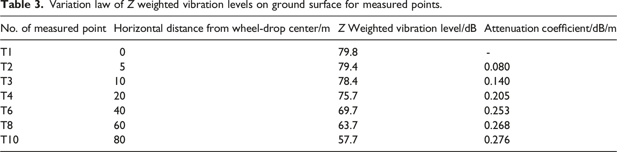
Variation law of Z weighted vibration levels on ground surface for measured points.
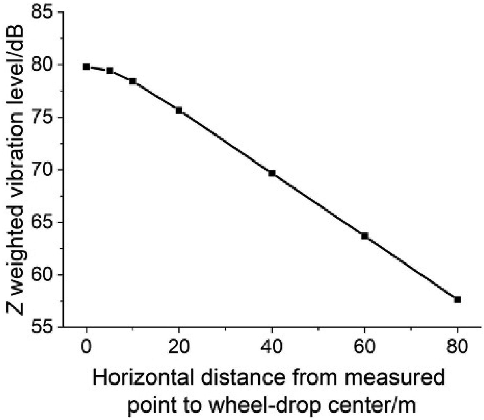
Variation of Z weighted vibration level with horizontal distance.
Parameter study
There are many factors affecting the ground vibration due to the operation of underground high-speed railways. The above prediction method is used to study the influence of train running speed, fastener stiffness, track slab thickness and tunnel burial depth on the ground vibration. The train running speed is taken as 200∼350 km/h, and other parameters are consistent with the above actual working condition. The location 40 m horizontally from the railway line is taken as the reference measured point to obtain the ground vibration levels under different train speeds, as shown in Figure 13. The vertical and lateral ground vibration levels increase with the increase in train speed. The peak vibration level gradually moves towards the high frequency. The ground vibration level changes uniformly with the train speed. When the running speed reaches 300 km/h, the vibration level is significantly amplified at 63 Hz. For every 50 km/h increase in train speed, the Z weighted vibration level increases by about 2 dB. Ground vibration levels at different train speeds. (a) Vibration level. (b) Z weighted vibration level.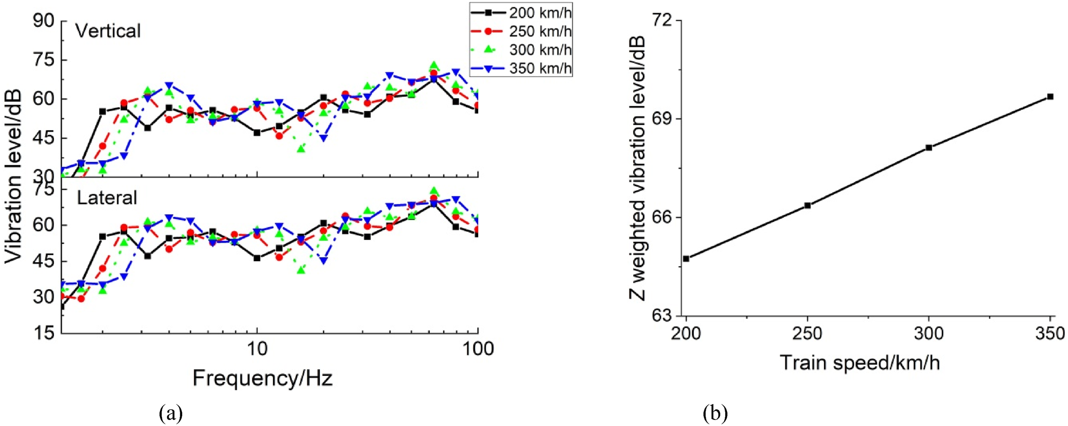
The stiffness of fasteners for the ballastless track in the tunnel is taken as 11.5 kN/mm, 35 kN/mm, and 105 kN/mm, respectively. The ground vibration level changes with the fastener stiffness as shown in Figure 14. The fastener has an isolating effect above a certain frequency which is the resonance frequency of the vehicle unsprung and track mass on the stiffness of the track. The influence of changes in fastener stiffness on the ground vibration level is concentrated in the frequency range above 20 Hz. The smaller fastener stiffness leads to the greater ground vibration level within 20∼50 Hz. The rise in vibration level around 25∼50 Hz can be attributed to the larger rail receptance due to the reduced track stiffness. As a result the resonance of the unsprung mass on the track stiffness occurs in this frequency range. The ground vibration level is positively correlated with the fastener stiffness above 79 Hz. If it is planned to control ground vibration by adjusting fastener stiffness, the target frequency range of vibration reduction should be clearly defined. Ground vibration levels for different fastener stiffnesses.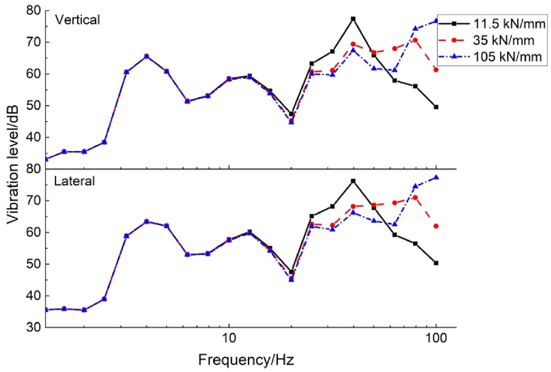
The thickness of the track slab is taken as 0.13, 0.26, 0.36, and 0.52 m, respectively. The influence of the track slab thickness is compared as shown in Figure 15. The change of the track slab thickness has little impact on the ground vibration caused by the underpassing high-speed railway, which is almost negligible. As one part of the transmission path, the track slab has very weak effect on the ground vibration attenuation property because of its larger density and smaller damping of the slab concrete compared with the soil around tunnel. The track slab thickness should not be taken as a control factor to reduce ground vibration. Ground vibration levels for different track slab thicknesses.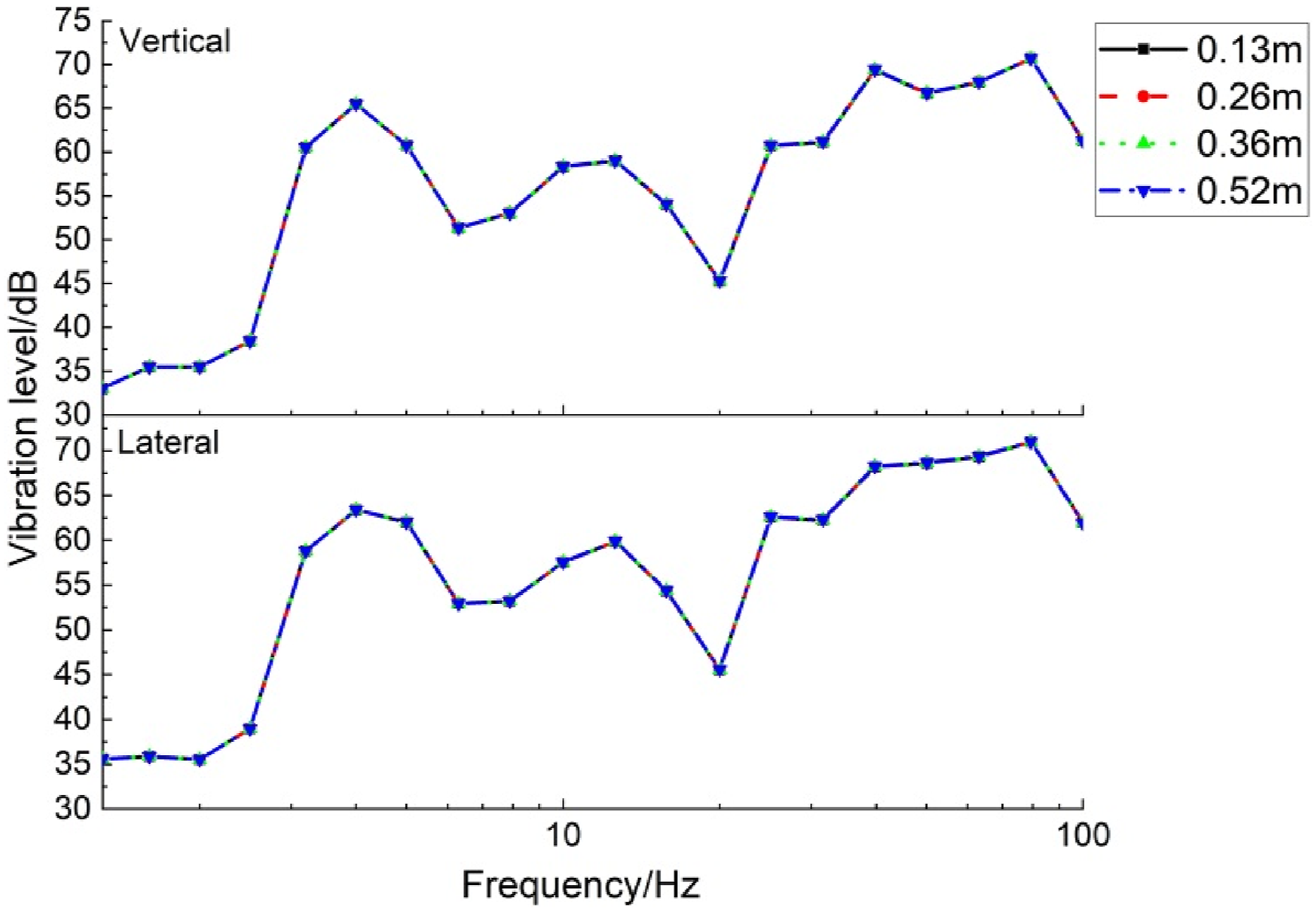
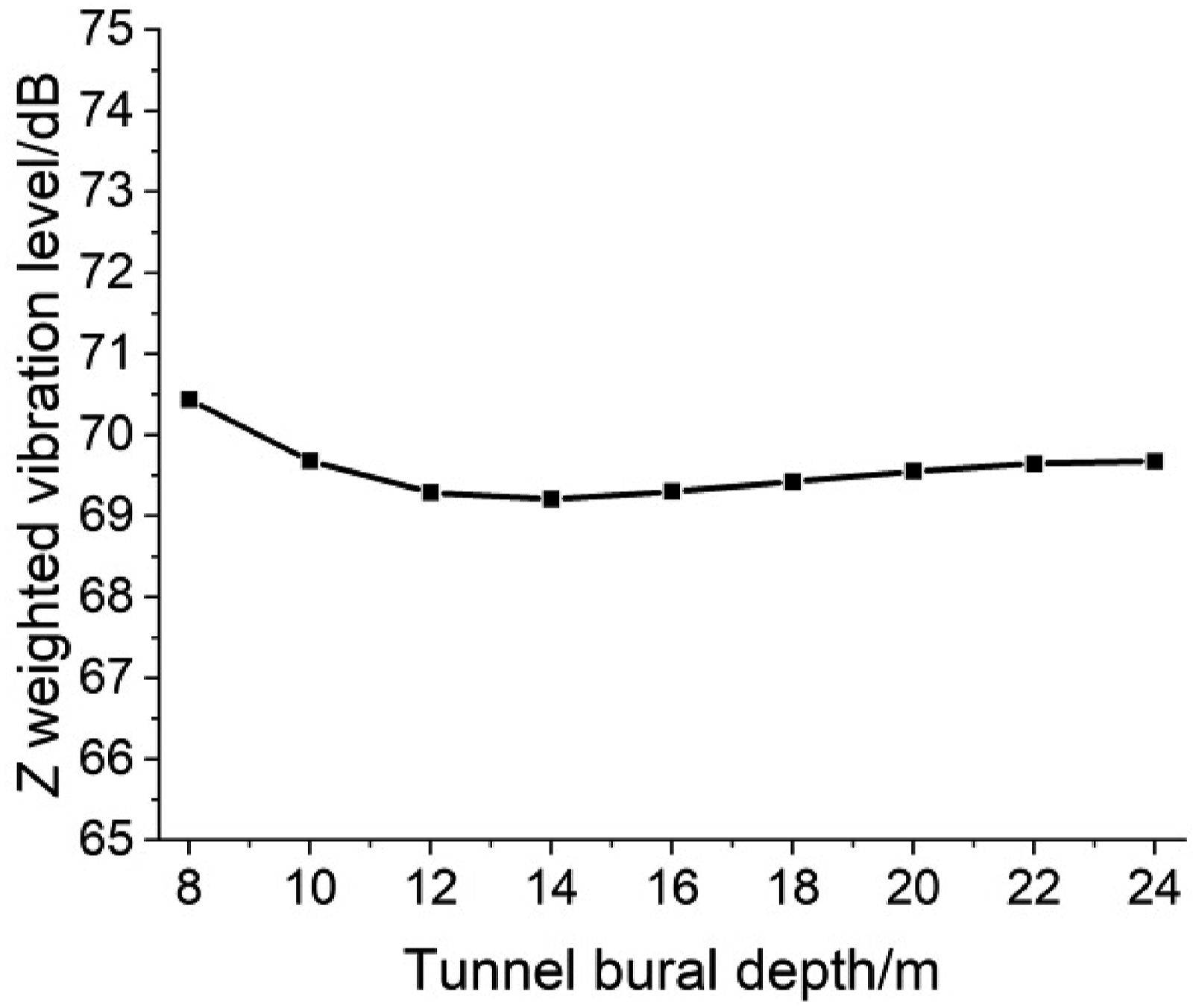
The tunnel burial depth is taken as 8, 10, 12, 14, 16, 18, 20, 22, and 24 m, respectively. The vertical and lateral ground vibration levels corresponding to different burial depths are shown in Figure 16. The Z weighted vibration level is shown in Figure 17. The vertical ground vibration level does not change significantly with the burial depth of tunnels within 3.2 Hz. The vertical ground vibration level decreases with the increase of the tunnel burial depth above 4 Hz. The deeper tunnel burial depth leads to the higher vibration level within 10∼20 Hz. When the tunnel burial depth is larger than 14 m, the peak vertical vibration level is subject to a relatively small variation within 25∼63 Hz due to the smaller damping of the limestone. The wavelength in the ground is very long in the low frequency range. The distance between the railway line and the ground surface is within a fraction of a wavelength. So for the deeper tunnel burial depth, the ground vibration has no significant attenuation in the low frequency range. It attenuates in a fluctuating tendency in the medium frequency range. The vibration attenuation at high frequencies is faster and greater than that at low frequencies. The Z weighted vibration level decreases with the deeper tunnel burial depth, but increases slightly above 14 m, which can be attributed to the reflection and superposition of vibration waves in the layered ground. The ground layer deeper than 15 m is made of limestone which has the higher wave reflection capacity at its interface (see Table 1). To limit the tunnel burial depth of high-speed railways within a reasonable range can effectively reduce the ground vibration. Ground vibration levels for different tunnel burial depths. Z weighted vibration level for different tunnel burial depths.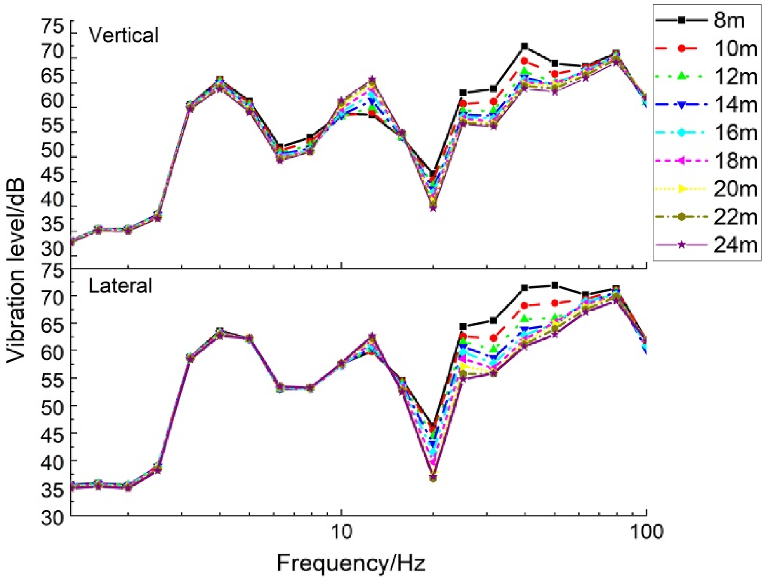
Conclusions
The wheel-drop impact test in the high-speed railway tunnel is designed to clarify the transmission characteristics of the ground vibration for the surrounding soil mass. The vehicle-track-tunnel-ground semi-analytical three-dimensional model is established to determine the force density, which is taken as the initial dynamic condition for the effect of running train to obtain the amplitude-frequency characteristic and transmission law of the ground vibration. The parameter studies on train speed, track parameters and tunnel burial depths have conducted. (1) Based on the wheel-drop test, the ground vibration is greatly attenuated within 10 m from the track centerline, with an attenuation rate of up to 70%. The vertical vibration amplitude is obviously larger than that of the other two directions. The longitudinal vibration transmits the fastest, while the lateral vibration amplitude is the smallest with the slowest attenuation speed. The main frequency of the ground is within 20 Hz. (2) With consideration of the unperpassing train at the speed of 350 km/h, the vertical and lateral ground vibration levels within 80 m are 20∼80 dB and 43∼72 dB, respectively. The vertical vibration level is about 9 dB higher than the lateral average to the maximum within the range of 40 m. The lateral vibration level is about 13 dB higher than the vertical average to the maximum beyond the range of 40 m. The frequencies for the peak vertical ground vibration are 4 Hz, 13 Hz, 25 Hz, 40 Hz, and 79 Hz. The maximum attenuation coefficient of the Z weighted vibration level attenuating faster with the farther distance reaches 0.276 dB/m. The Z weighted vibration level of the ground increases by about 2 dB with the train speed increasing by 50 km/h. (3) The effect of the fastener stiffness on the ground vibration level is in the frequency range above 20 Hz. The smaller fastener stiffness leads to the greater ground vibration level within 20∼50 Hz. The ground vibration level is positively correlated with the fastener stiffness above 79 Hz. The effect of the track slab thickness is negligible. (4) The vertical ground vibration level decreases with the deeper tunnel burial depth above 4 Hz, but increases within 10∼20 Hz. The tunnel burial depth has little impact on the change in the Z weighted vibration level for the tunnel burial depth larger than 14 m. To limit the tunnel burial depth deeper than 14 m can effectively reduce the ground vibration.
Footnotes
Acknowledgements
The corresponding author is sincerely grateful to thank Pro. Thompson D.J. and Dr Ntotsios E. from Institute of Sound and Vibration Research, University of Southampton for the guidance on the research work.
Declaration of conflicting interests
The author(s) declared no potential conflicts of interest with respect to the research, authorship, and/or publication of this article.
Funding
The author(s) disclosed receipt of the following financial support for the research, authorship, and/or publication of this article: This work was supported by The Key R&D Project of Sichuan Province (Grant No. 2019YFG0040).