
Abstract
The core topology of sandwich panels plays a pivotal role in determining their mechanical performance, weight efficiency, and multifunctional capabilities. This paper experimentally and numerically investigates the mechanical performance of corrugated core sandwich panels with varied core geometries, including triangular, trapezoidal, rectangular, and circular, under compression and bending loads. Panels were fabricated using polylactic acid (PLA) and tested both with and without the addition of recycled polyethylene terephthalate (R-PET) foam inserts. R-PET foam, a sustainable material, offers benefits in strength-to-weight ratio, moisture, thermal, and acoustic insulation. The results indicate that core geometry significantly impacts load-bearing capacity, with rectangular cores exhibiting superior compression strength while triangular cores excel under bending loads. The foam inserts, placed within the core channels, notably improved compressive and flexural load capacity by, on average, 270 and 220% across all geometries with only a 30% increase in weight. Failure modes were also observed, with initial mode 1 buckling of the core walls and localized deformation leading to subsequent failure mechanisms such as delamination and core debonding. ABAQUS was used to develop finite element models for flatwise compression and three-point bending tests for all core geometries. The numerical simulations closely aligned with the experimental results, providing insights into stress distribution, the influence of cell wall thickness, and the impact of corrugation angles on panel performance. These findings highlight the critical role of core geometry and the impact of foam inserts in enhancing structural integrity in sandwich panels.
Introduction
Sandwich panels are widely utilized across various industries due to their high strength and stiffness-to-weight ratio, as well as shock absorption capabilities, playing a critical role in applications such as aerospace, marine, and construction. These panels consist of two rigid face sheets enclosing a lightweight core that is typically designed to enhance structural capacity and minimize weight through material selection or core topology.1,2 The materials used for the core of sandwich panels vary based on the application, ranging from balsa wood and metals to foams and advanced composites.3–5 Commonly used and studied core designs include honeycomb cores, truss cores, and corrugated cores.6–8 Each material and geometry offers unique mechanical properties, making sandwich panels adaptable to a wide range of industrial requirements such as weight, strength, cost, and ease of fabrication.
Corrugated-core sandwich panels have emerged as a versatile solution in modern engineering due to their superior mechanical and insulation properties, such as high energy absorption and high stiffness-to-weight ratio, as well as preventing moisture retention.9–14 Selecting the optimal corrugated core sandwich panels can be challenging due to the wide range of available core geometries. Each geometry offers distinct advantages and drawbacks in terms of mechanical performance, manufacturing complexity, and weight. Due to the high-impact resistance capability of corrugated core sandwich panels, many researchers have focused on this aspect. Wentao et al. 15 and Dolati et al. 16 investigated the low-velocity and high-velocity impact testing of trapezoidal cores, respectively, while et al. 17 examined the dynamic response of near-field air blasts of triangular cores. However, the impact has not been the only focus, and other researchers have investigated singular geometry corrugated cores under tensile displacement, 18 vibration-damping, 19 and compression. 13 In addition to evaluating the common core geometries, many researchers have explored hybrid corrugated core designs such as trapezoidal-triangular hybrid and layered corrugated hybrid core, and investigated their mechanical response, weight, and manufacturability.20–23
In recent years, a growing effort has been made to determine the optimal core geometry under various loading conditions. To this effort, diverse corrugated core geometries have been investigated and compared under multiple loading conditions. 24 Previous work on the bending and compression performance of corrugated panels shows interesting results. Xia F. et al. 25 compared corrugated panels made out of aluminum with cores of various shapes under longitudinal three-point bending, showing that rectangular panels have the highest load capacity, followed by trapezoidal, triangular, and sinusoidal. Abedzade et al. 26 evaluated the effect of core geometry on flexural stiffness and transverse shear rigidity of triangular, trapezoidal, and rectangular corrugated core sandwich panels made with woven glass fiber using vacuum-assisted resin transfer molding (VARTM). The results showed that the triangular core has the highest flexural load capacity with the least amount of deflection. Furthermore, Yu R. et al. 27 investigated the response of five different core geometries under minor energy impact and high energy impact, as well as compression. It was determined that Trapezoidal and rectangular had the highest load capacity before buckling, respectively, while arc-shaped and sinusoidal cores exhibited the lowest strength. A comparison of existing research highlights that material selection and failure mechanisms significantly influence the performance of each core geometry. Furthermore, no single geometry exhibits optimal performance under all loading conditions; therefore, the selection of core geometry should be based on specific loading requirements and applications.
One of the challenges of researching different core geometries or optimizing them is sample manufacturing. Traditional processes, for instance, hand lay-up for composites and forming for metals, present limitations compared to modern approaches such as additive manufacturing, notably high waste, limited design flexibility, and difficulty with complex geometry. Additive manufacturing has revolutionized the fabrication of sandwich panels by enabling the precise production of complex geometries with minimal waste. 28 As a result, many researchers have utilized additive manufacturing methods for development research, including optimization of corrugated core geometry.29–31 Iranmanesh et al. 32 investigated the effect of variation in core geometry on the structural performance of sandwich panels using 3D printing. This study assessed different geometric configurations, such as honeycomb, lattice, and custom-design structures, to evaluate their impact on properties such as stiffness and strength, providing valuable insight into optimizing the core design of sandwich panels.
In addition to core design, the integration of sustainable materials has gained traction. Polyethylene Terephthalate (PET) foam is a closed-cell thermoplastic foam that is used in a variety of applications, including construction, transportation, and marine. R-PET foam infill offers notable benefits in sandwich panels, including moisture resistance and thermal and acoustic insulation.33–36 This material is highly recyclable and has a much lower carbon footprint.37,38 Foam-filled honeycomb panels are widely used in the industry due to their multi-functionality. The addition of foam to a structural panel can improve stiffness, strength, and energy absorption as well as integrate insulation capability.39–41 Due to the open channel design of the corrugated core sandwich panels, the structure can more conveniently be filled with foam, creating great opportunities for the use of this multifunctional structure. Multiple numerical and experimental studies have been conducted on a single geometry foam-filled corrugated core sandwich panel, revealing enhanced energy absorption, but the research on these panels under compression and bending is limited.42–44 Taghizadeh et al. 45 studied PVC foam-filled corrugated core sandwich panels with rectangular, trapezoidal, and triangular geometries under planar, linear, and concentrated compression loading. Incorporating foam infill within corrugated core sandwich panels results in the development of multifunctional panels suitable for applications such as construction, effectively replacing panels traditionally used solely for structural support or insulation.
The comparative analysis of core geometries, both with and without foam infill, not only offers valuable insights into the mechanical performance of each configuration under compressive and bending loads but also facilitates the evaluation of enhancements in mechanical properties relative to the associated increase in weight. This research compares four distinct corrugated core geometries under compressive and bending loads to determine the optimal design. Subsequently, the panels are filled with R-PET foam, and their mechanical performance is investigated and compared to their hollow counterparts, with careful consideration of the associated weight increase. Upon identifying the optimal corrugated core geometry for multifunctional panels under compressive and bending loads, further optimization of this geometry is necessary. In this study, numerical models were developed for each corrugated core configuration and validated against experimental compression and bending results. These models are utilized to analyze the influence of various geometric parameters on the performance of the panel.
Materials and methods
Core design and fabrication
This study examines and compares four corrugated core geometries, triangular, trapezoidal, rectangular, and circular, as shown in Figure 1. The designs were developed using insights from the literature, mechanical performance considerations, and practical manufacturing constraints. The overall dimensions of the panel were limited by the 3D printer bed size, while the panel, core walls, and skin thicknesses were specified by the industry partner. To improve load distribution, the maximum feasible number of corrugations was selected, with corrugation angles (45°–85°) and amplitudes that align with values reported in previous studies, to yield better performance. For a fair comparison between geometries, key parameters such as skin thickness, core wall thickness, and number of corrugations were kept constant, as these directly influence strength, stiffness, and energy absorption. All geometries were modeled in SOLIDWORKS for both manufacturing and simulation purposes. Section view (Dimensions in mm) and isometric view of four sandwich panels with corrugated geometric configurations.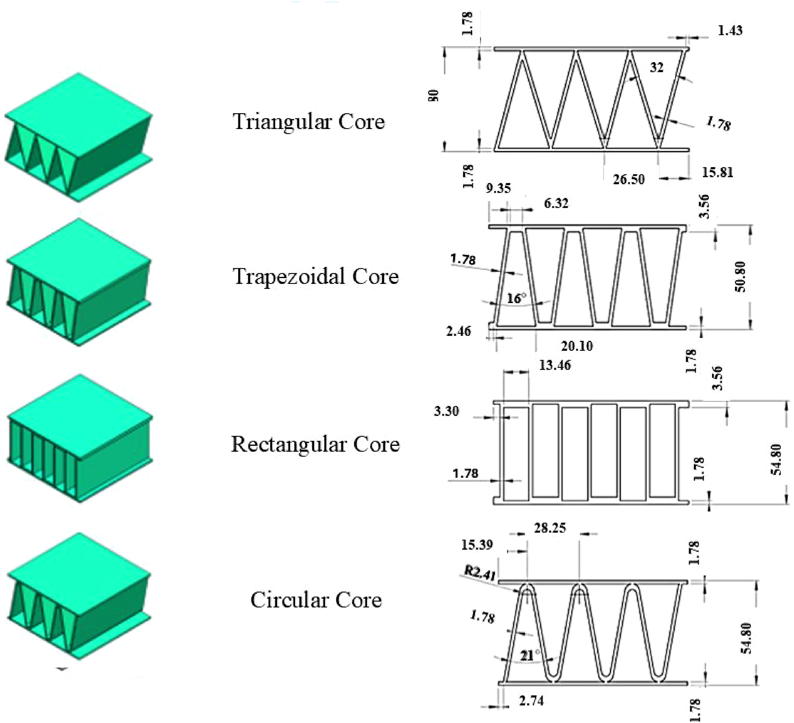
3D print settings.
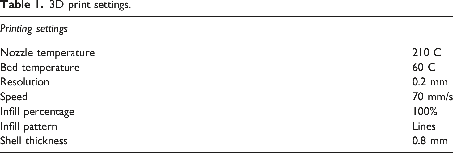
For panels incorporating foam cores, recycled PET (R-PET) foam with a density of 80 kg/m3 was utilized. The foam was supplied as 2-inch (50.8 mm) thick square panels, which were later shaped to the required geometries using a hot wire cutter. Compression tests on the R-PET foam revealed its anisotropic nature, attributed to the directional cell formation during manufacturing. To account for this, all foam infill pieces were cut in the same orientation, ensuring uniformity in material properties across samples.
The foam cores were bonded to the corrugated channel walls using a moisture-curing polyurethane mono-component adhesive. This adhesive was applied evenly on the surface of the foam and activated by spraying a fine mist of water. Upon activation, the adhesive expanded to fill any gaps, creating an effective bond with the foam core by penetrating and sealing the open cells at the joint surfaces. This method demonstrates a practical approach to ensuring strong adhesion and consistency in the manufacturing of sandwich panels, highlighting the importance of material alignment and precision in assembly. However, variations in adhesive strength and imperfections, such as trapped air bubbles, can affect bonding consistency and may lead to stress concentration, resulting in localized failure initiation, particularly under shear loading. A step-by-step map of the sample manufacturing process is shown in Figure 2. Manufacturing process used to fabricate corrugated core sandwich panel samples with and without R-PET foam infill.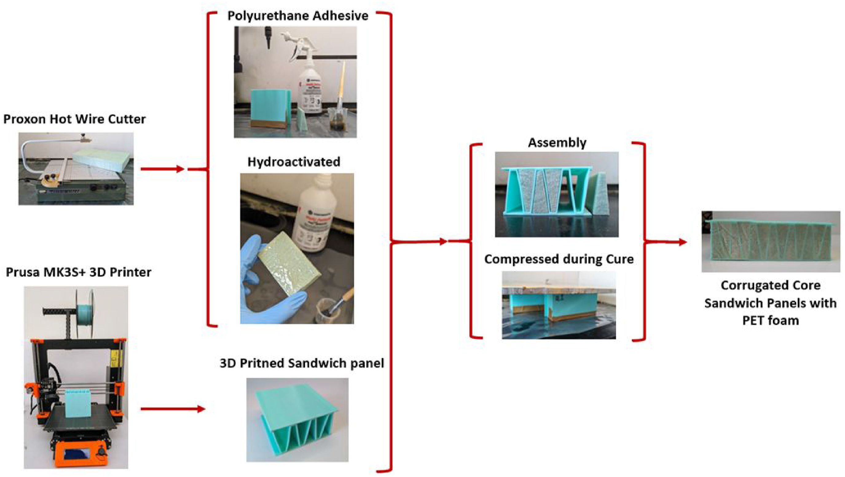
Material properties
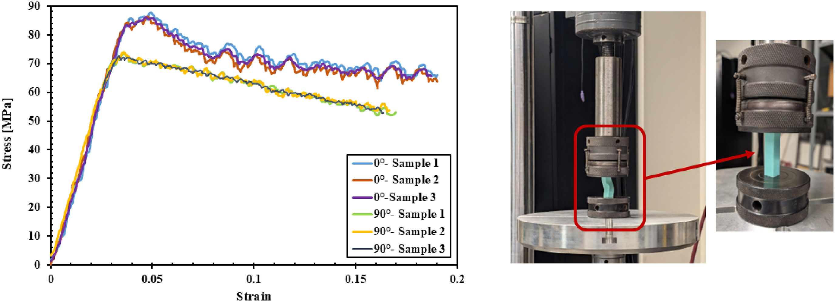
Accurate modeling of the response of 3D-printed parts requires precise measurement of their material properties. These properties are influenced not only by printer settings such as temperature, speed, orientation, and infill pattern, but also by the specific hardware used and the environmental conditions.46,47 To determine the mechanical properties of polylactic acid (PLA), dog-bone samples were printed in the [0°], [90°], and [45°] orientations, and rectangular prism specimens were printed in [0°] and [90°] orientations and subjected to tensile and compression tests. While PLA is inherently isotropic, 3D-printed PLA exhibits anisotropic behavior due to the layer-by-layer deposition process, significantly affecting its mechanical properties based on the print orientation. Tensile and compression tests were performed according to ASTM D638-22 and ASTM D695-23 standards. The dimensions and specifications of the samples are shown in Figure 3. For both tensile and compression specimens, the [0°] print orientation corresponds to the y-axis, while the [90°] orientation corresponds to the x-axis. The [0°] samples were printed flat, resulting in layer-by-layer deposition along the z-axis. In contrast, the [90°] samples were printed in a standing position, with deposition occurring along the y-axis. Actual images and the corresponding technical drawing (dimensions in mm) of (a) Tensile Dog-bone specimens and (b) Compression specimens.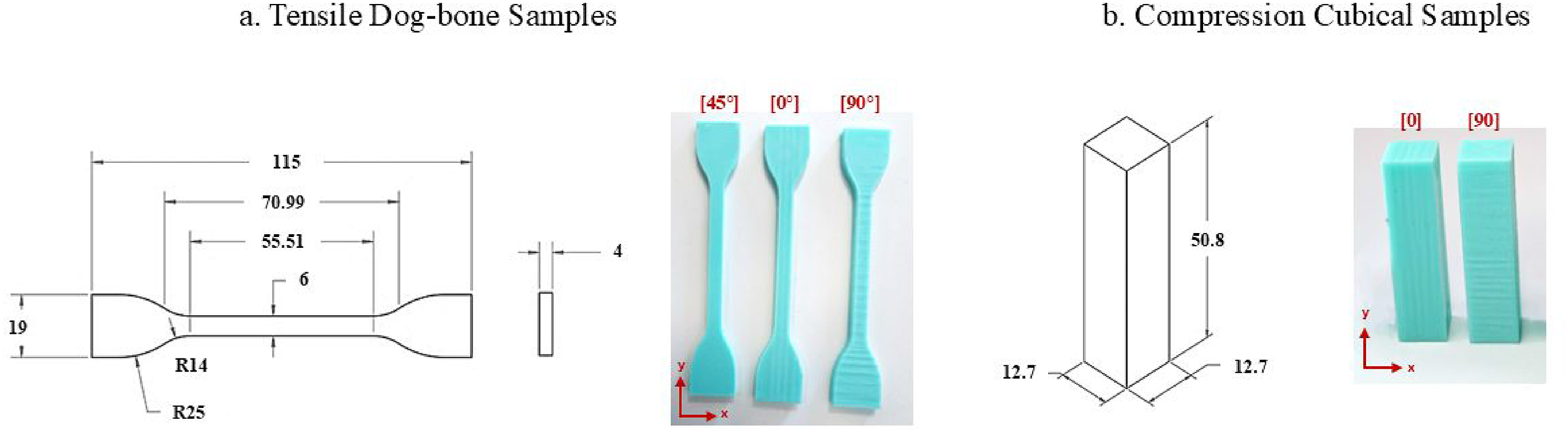
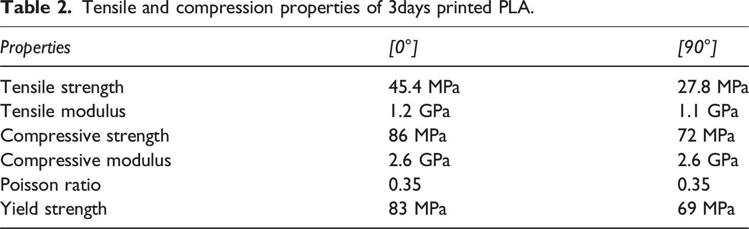
The results shown in Figures 4 and 5 demonstrate significant differences in the mechanical properties of 3D-printed parts, both between compression and tension as well as across various print orientations. Specifically, the compressive strength of 3D-printed PLA was found to be nearly double its tensile strength. Additionally, when the applied load was aligned perpendicular to the print direction (at a 90° orientation), the strength decreased due to weak interlayer bonding. Stress as a function of strain curves and tensile test setup for 3D-printed PLA samples. Stress as a function of strain curves and compression test setup for 3D-printed PLA samples.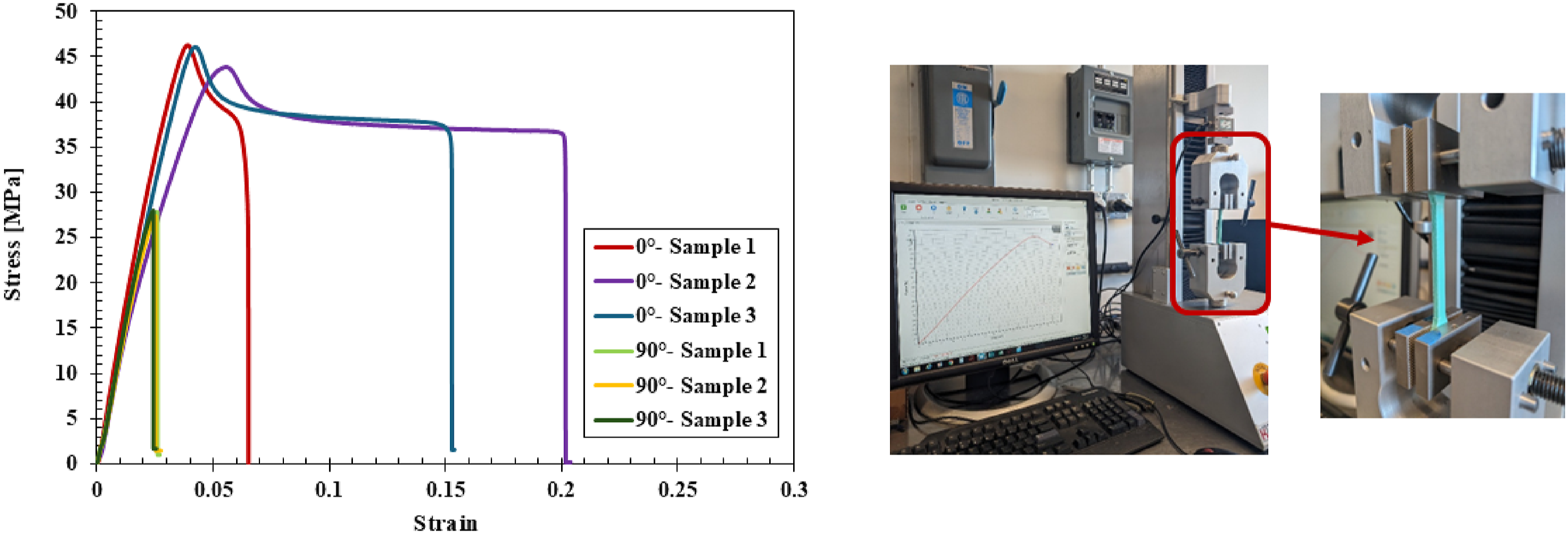
Tensile and compression properties of 3days printed PLA.
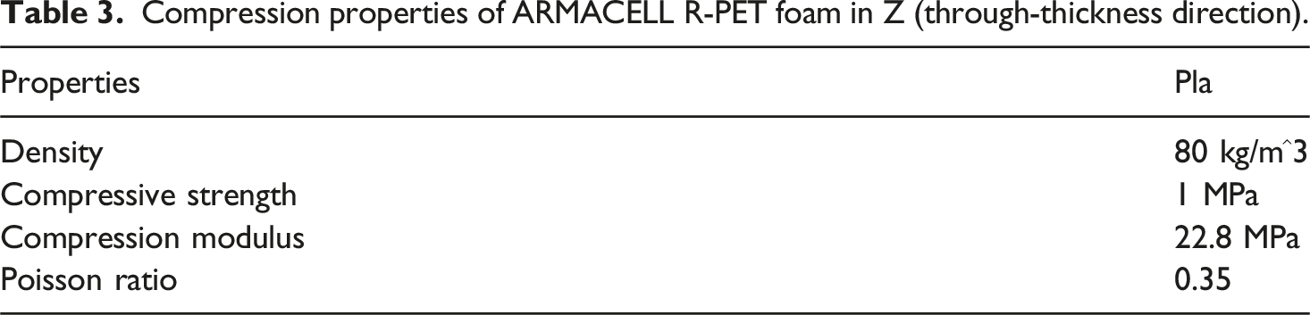
The infill material used in this study is a recycled polyethylene terephthalate (R-PET) foam supplied by ARMACELL, classified as a closed-cell thermoplastic foam. To characterize its mechanical properties, the foam was subjected to compression testing. As illustrated in Figure 6, the foam exhibited an initial resistance to deformation followed by cell-wall collapse under compressive loading, after which progressive crushing was observed. Upon reaching densification, a secondary increase in compressive strength occurred. Additionally, due to its micro-honeycomb architecture, the foam demonstrated anisotropic compressive behavior, with mechanical properties varying along the three principal directions. The compressive properties of the PET foam are shown in Table 3. Stress as a function of strain curves and compression test setup for R-PET foam samples. Compression properties of ARMACELL R-PET foam in Z (through-thickness direction).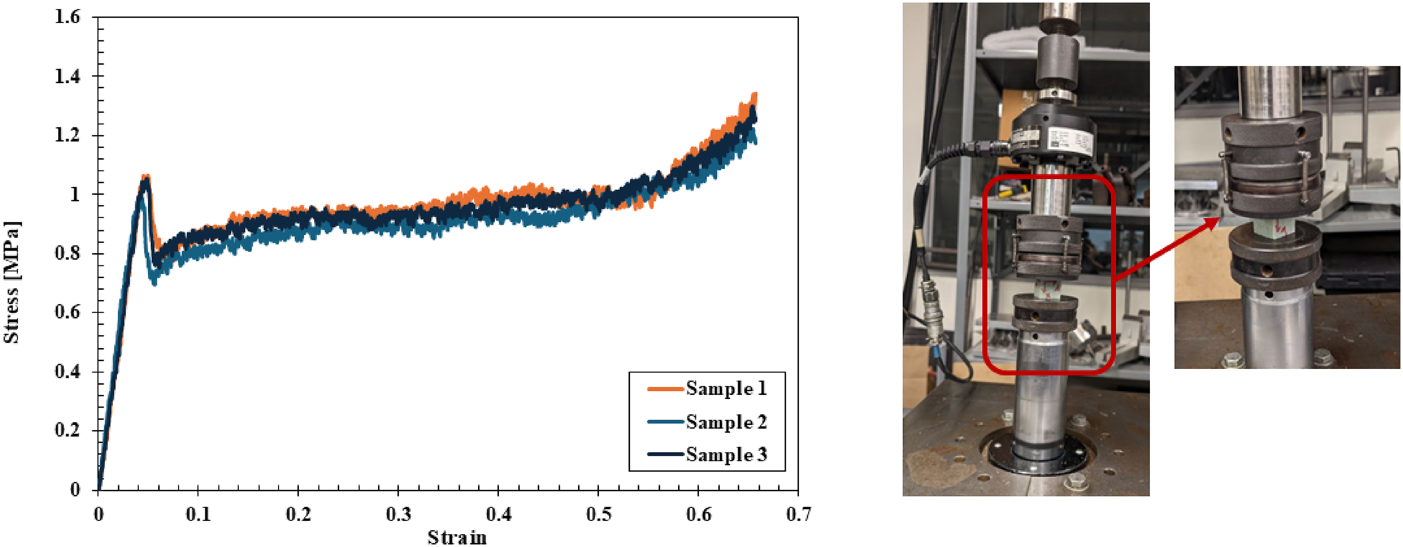
Experimental procedure
Following fabrication, the compression samples measuring 4 in. (101.6 mm) × 4 in. (101.6 mm) × 2 in. (50.8 mm) thick, both with and without foam infill, were subjected to flatwise compression tests to evaluate their mechanical performance. Flatwise compression tests were conducted using an INSTRON testing machine equipped with a 100 kN load cell, operating at a head displacement rate of 2 mm/min. The tests were performed in accordance with ASTM C365 standards. Three-point bending tests were conducted using a Universal MTS testing machine instrumented with a 100 kN load cell, running at a speed of 2 mm/min. The bending samples measured 8 in. (203.2 mm) × 3 in. (76.2 mm) × 2 in. (50.8 mm) thick, as per ASTM C393 standard, and the size limitation of the 3D printer bed. The testing setup and fixture for both flatwise compression and three-point bending tests are shown in Figure 7. (a). INSTRON 3400 and (b). Universal MTS testing machine equipped with flatwise compression and three-point bending test fixtures.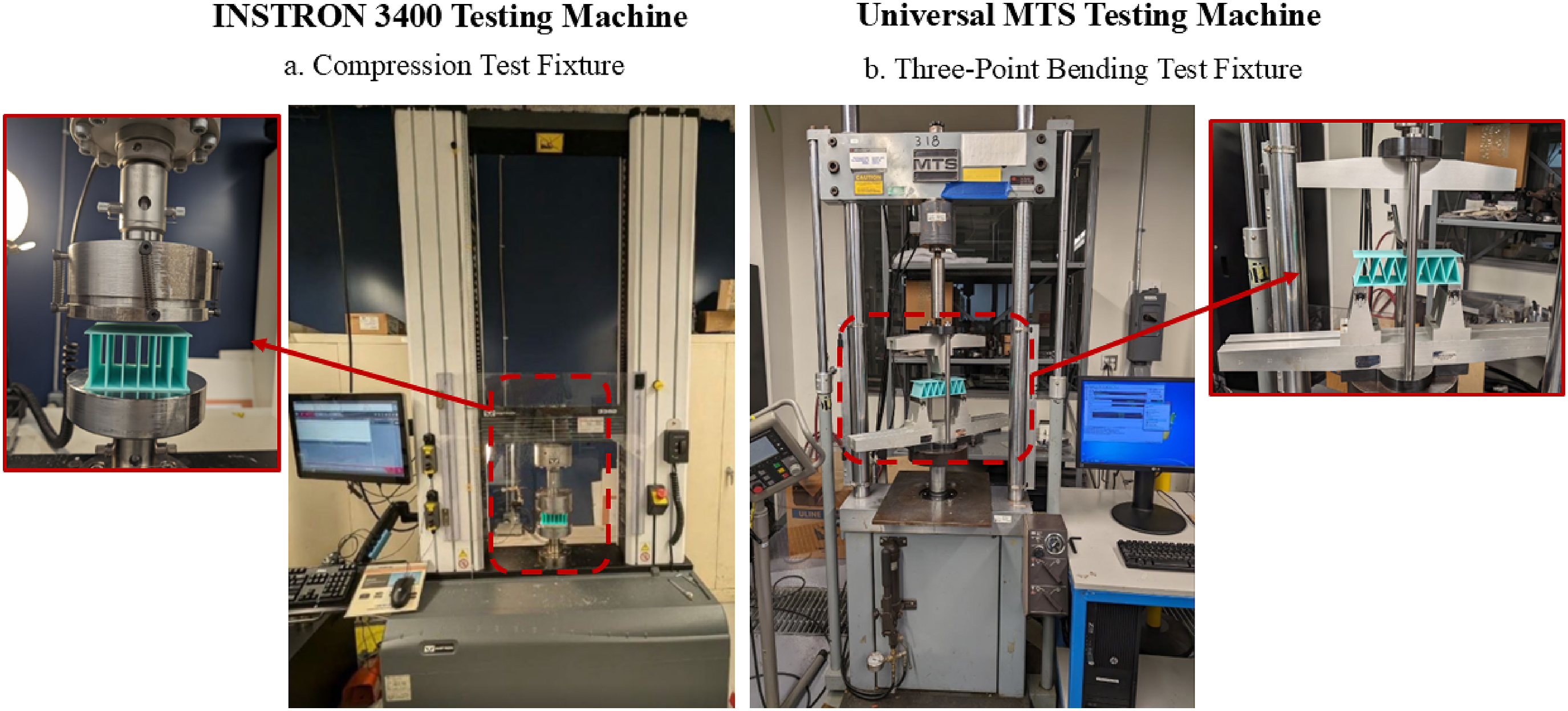
Numerical modeling
Abaqus was used to simulate the performance of each corrugated core geometry under compression and bending. The flatwise compression and three-point bending finite element models are shown in Figure 8. The flatwise compression model consists of the specimen as well as loading and circular support fixtures. The circular fixtures are sufficiently stiff compared to the specimen and are thus defined as rigid bodies. A surface-to-surface contact was defined to simulate the interaction between the specimen and the fixtures, with self-contact set for the surfaces of the specimen to prevent penetration of elements due to large deformation. The bottom fixture was set to have no degrees of freedom, while the top fixture was set to only displace in the negative y-direction. A mesh density study was performed to evaluate the influence of element size, and the results showed that load capacity until buckling predictions were not sensitive to mesh refinement. However, further damage modeling is expected to be more influenced by both the mesh density and element type. The hex elements provided satisfactory accuracy and computational efficiency. An isotropic elastic–plastic material model was adopted, with elastic properties defined from experimentally measured Young’s modulus and Poisson’s ratio, and plastic behavior calibrated from yield stress–plastic strain data. All materials were assumed to be isotropic in all directions. Finite element model for flatwise compression and tree point-bending.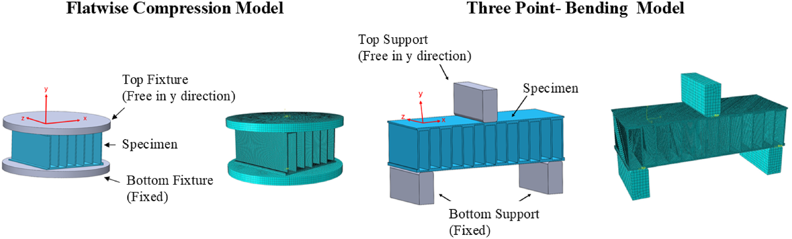
The three-point bending model consists of the specimen, two rectangular supports, and a rectangular loading fixture on the top surface. The setting for the bending model was similar to the compression model. Additional boundary conditions were inserted to prevent the sample from sliding in the x and z directions. In this configuration, the two longitudinal ends of the specimen were constrained from sliding linearly in the z direction only, with further constraints applied as rotational restraints along the x- and y-axes. These models were created for all four geometries and were compared with the experimental results.
Results and discussion
Flatwise compression without foam infill
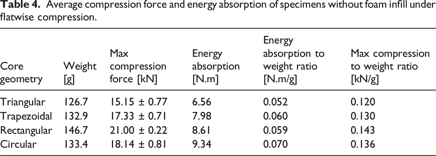
Corrugated core panels with four distinct geometries were fabricated and evaluated under flatwise compression testing. Figure 9 presents the samples before and after buckling, demonstrating that all panels experienced Mode 1 buckling under compression. Variations in buckling direction were observed, attributed to random imperfections introduced during the 3D printing process. The force-displacement curve exhibited an initial non-linear response attributed to surface irregularities and layer gaps inherent to 3D printing, followed by a linear elastic deformation phase once full contact was established between the fixture and the sample surface. As the force increased, plastic deformation and buckling occurred, marked by a deviation from linearity in the curve, with the peak load corresponding to the maximum load-bearing capacity before buckling. Among the tested geometries, the rectangular core exhibited the highest load-carrying capacity, followed by the circular and trapezoidal cores, while the triangular core demonstrated the lowest capacity. The average maximum compression force and energy absorption values, normalized for variations in panel weight, are summarized in Table 4. Each geometry was tested three times to ensure repeatability of the results. Corrugated core samples without infill before under-compression loading. Average compression force and energy absorption of specimens without foam infill under flatwise compression.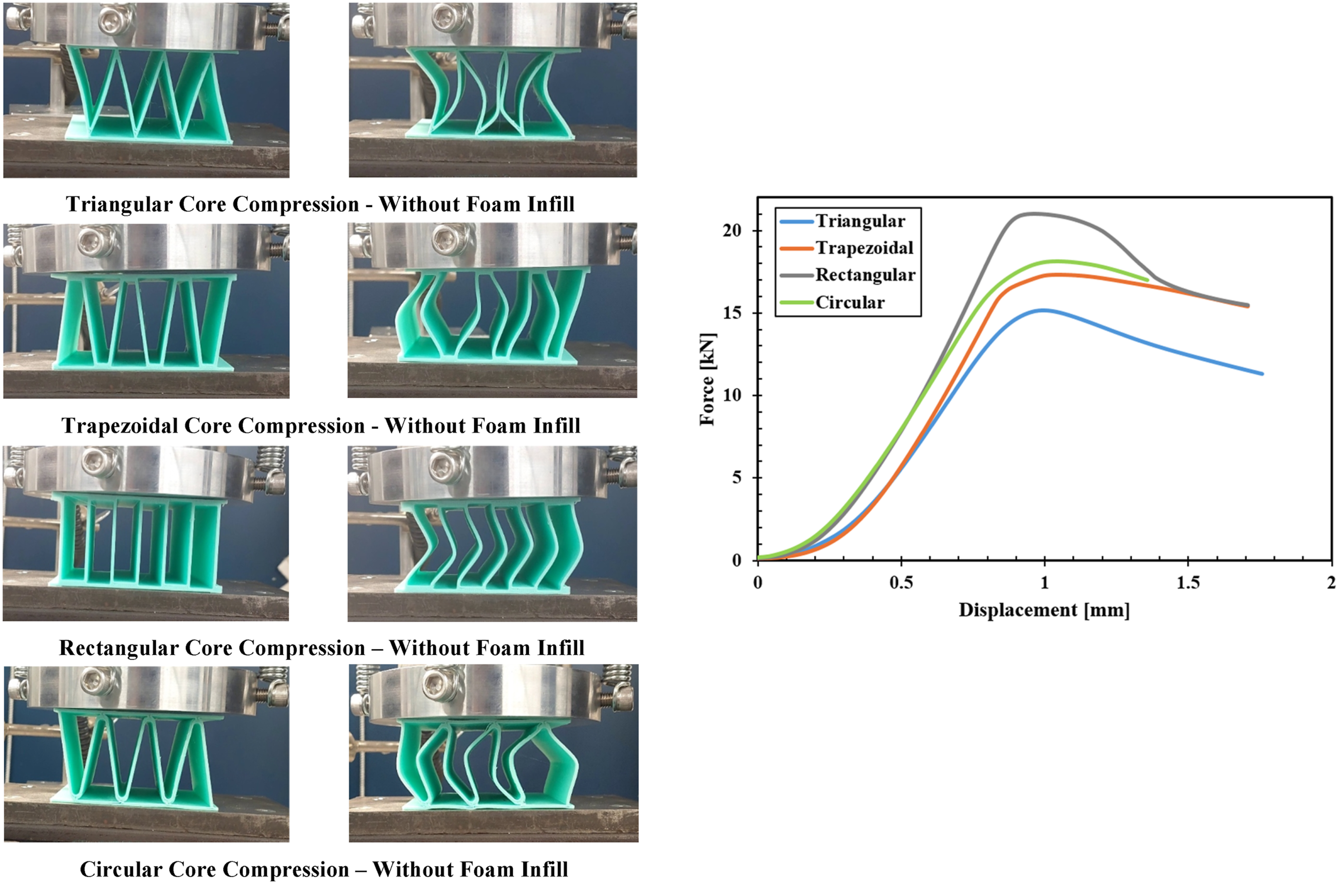
Flatwise compression with foam infill
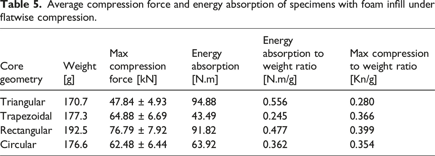
Following the addition of recycled PET foam to the corrugated core panels, compression tests were performed to evaluate the effect of foam inclusion. Figure 10 depicts the panels before and after failure, highlighting the distinct failure modes. Similar to the hollow core panels, all samples failed primarily due to buckling; however, the introduction of adhesive and R-PET foam resulted in additional failure mechanisms. The direction of buckling and the failure locations were influenced by manufacturing irregularities from the 3D printing process, foam infill characteristics, and the adhesion between the foam and the corrugated walls. In contrast to the hollow panels, a more pronounced brittle failure was observed, with the corrugated walls either fracturing at the midpoint or detaching entirely. The force-displacement curve for the R-PET foam-infilled panels exhibited a linear elastic region followed by a sharp peak, corresponding to adhesive shear failure, which subsequently led to plastic deformation and buckling. Post-buckling, core walls crush the foam, causing cell wall collapse and densification. This densification resulted in a slight increase in load before the final failure, which was characterized by a brittle fracture of both the foam and the corrugated core. The data summarized in Table 5 indicates a significant increase in load-carrying capacity for the foam-filled panels compared to their hollow counterparts. As observed previously, the rectangular cores exhibited the highest strength, followed by the trapezoidal, circular, and triangular cores, with the triangular core demonstrating the lowest capacity. Each geometry was tested three times to ensure repeatability of the results. Corrugated core samples with infill before under-compression loading. Average compression force and energy absorption of specimens with foam infill under flatwise compression.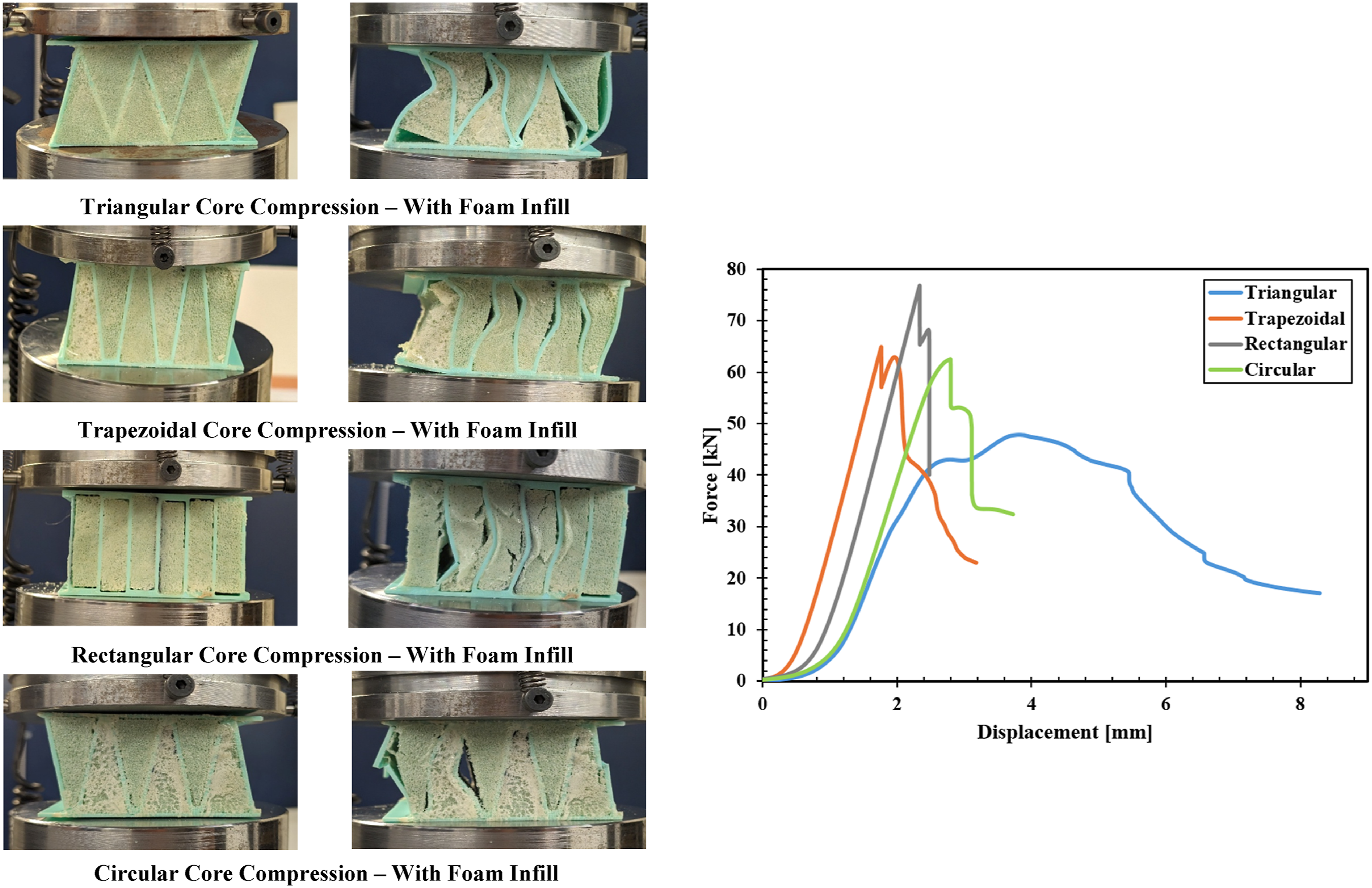
Three-point bending without foam infill
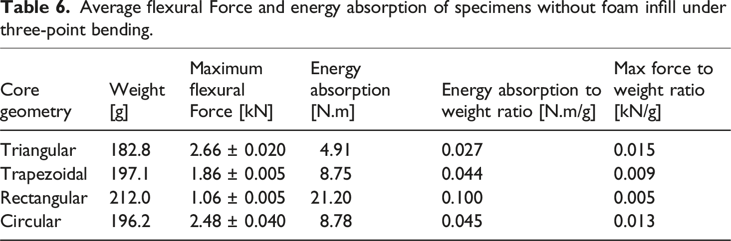
The corrugated core samples were subjected to three-point bending tests, with the pre-and post-buckling configurations shown in Figure 11. The triangular, trapezoidal, and circular cores exhibited localized buckling at the unit cell directly beneath the top fixture, with deformation propagating to adjacent unit cells. In contrast, the rectangular core underwent global deformation. The force-displacement curve displayed an initial linear elastic response, followed by a deviation indicating the onset of plastic deformation and subsequent buckling. The triangular core failed rapidly due to stress concentration at the core-skin interface, while the circular and trapezoidal cores exhibited more controlled buckling failures. The rectangular core, however, transitioned into the plastic region and experienced significant displacement due to the deformation of the structure. According to the data summarized in Table 6, the triangular core demonstrated the highest flexural load capacity, followed by the circular and trapezoidal cores. Each geometry was tested three times to ensure repeatability of the results. Corrugated core samples without infill before under Three-point bending loading. Average flexural Force and energy absorption of specimens without foam infill under three-point bending.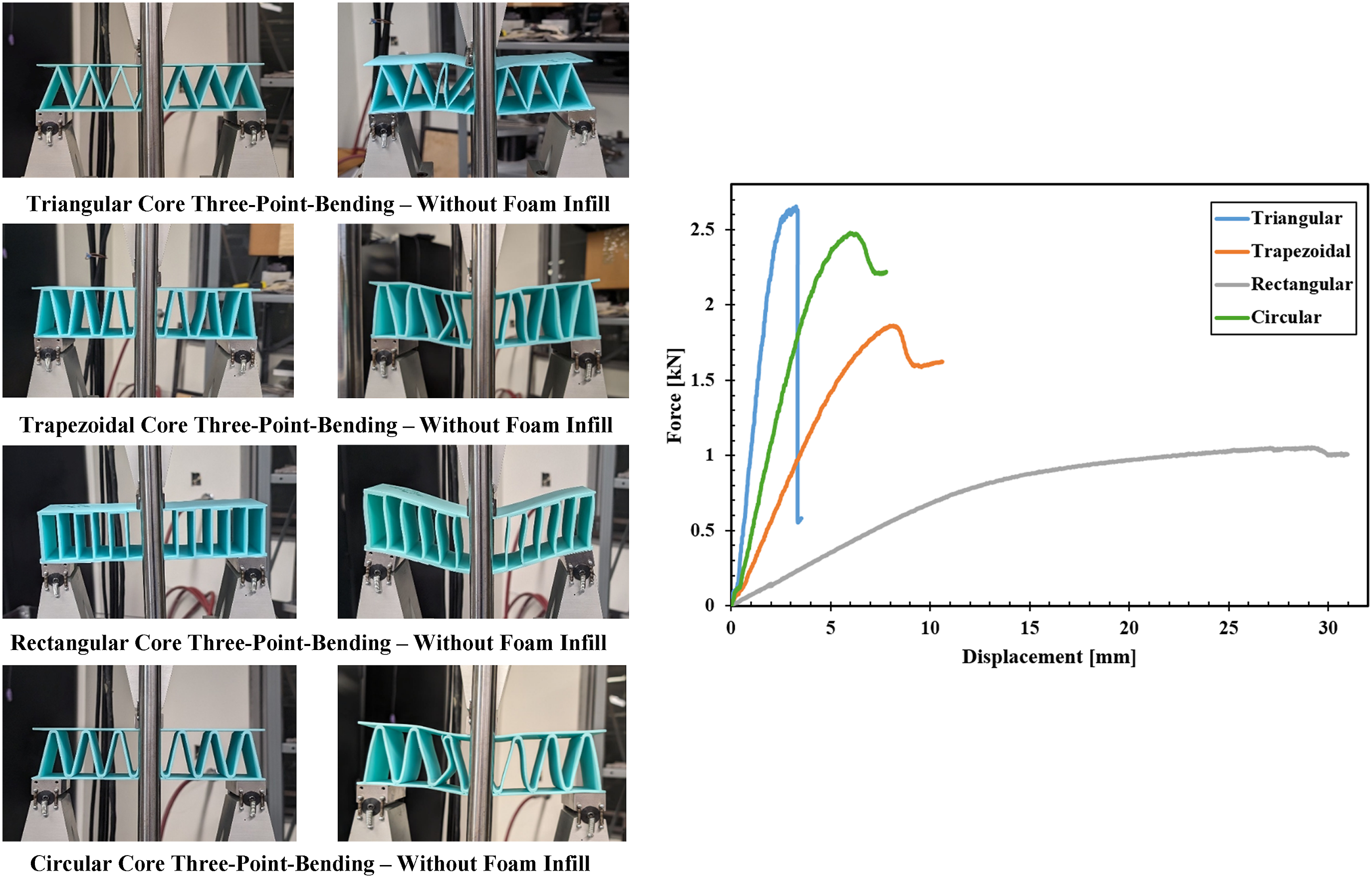
Three-point bending with foam infill
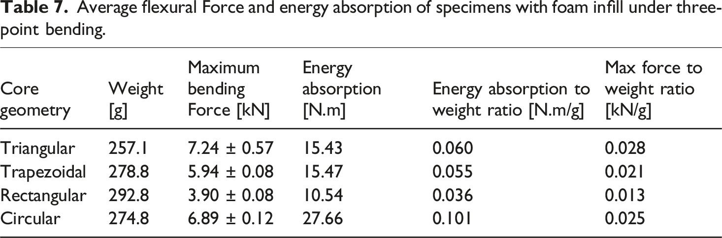
The foam-filled corrugated core samples were subjected to three-point bending tests, with the pre- and post-failure configurations shown in Figure 12. Similar to the hollow samples, the triangular, trapezoidal, and circular panels exhibited localized failure, while the rectangular panel underwent global deformation. In addition to buckling failure, other failure mechanisms, including adhesive shear, core cracking, and foam densification, were observed. The force-displacement curve for the foam-filled samples displayed an initial linear elastic region, followed by plastic deformation and buckling. As the load increased, adhesive shear failure occurred at the center of the panels. Concurrently, as the core buckled, foam cell walls were crushed, leading to densification and a slight plateau in the curve. Unlike the hollow panels, where buckling was confined to the middle channels, the R-PET foam facilitated more gradual energy distribution to the outer cores as the central corrugated walls failed. In the circular panel, the localized buckling of the central channel resulted in fracture failure of the bottom skin, causing a sudden load drop due to stress concentration from manufacturing irregularities. A second bending test on the circular core revealed different failure mechanisms under similar compressive loads. The rectangular panel exhibited global deformation, and as deformation progressed, adhesive shear failure at the corners led to a small, abrupt drop in force. According to the data summarized in Table 7, the triangular core demonstrated the highest flexural load capacity, followed by the circular, trapezoidal, and rectangular cores. Each geometry was tested three times toensure repeatability of the results. Corrugated core samples with infill before under Three-point bending loading. Average flexural Force and energy absorption of specimens with foam infill under three-point bending.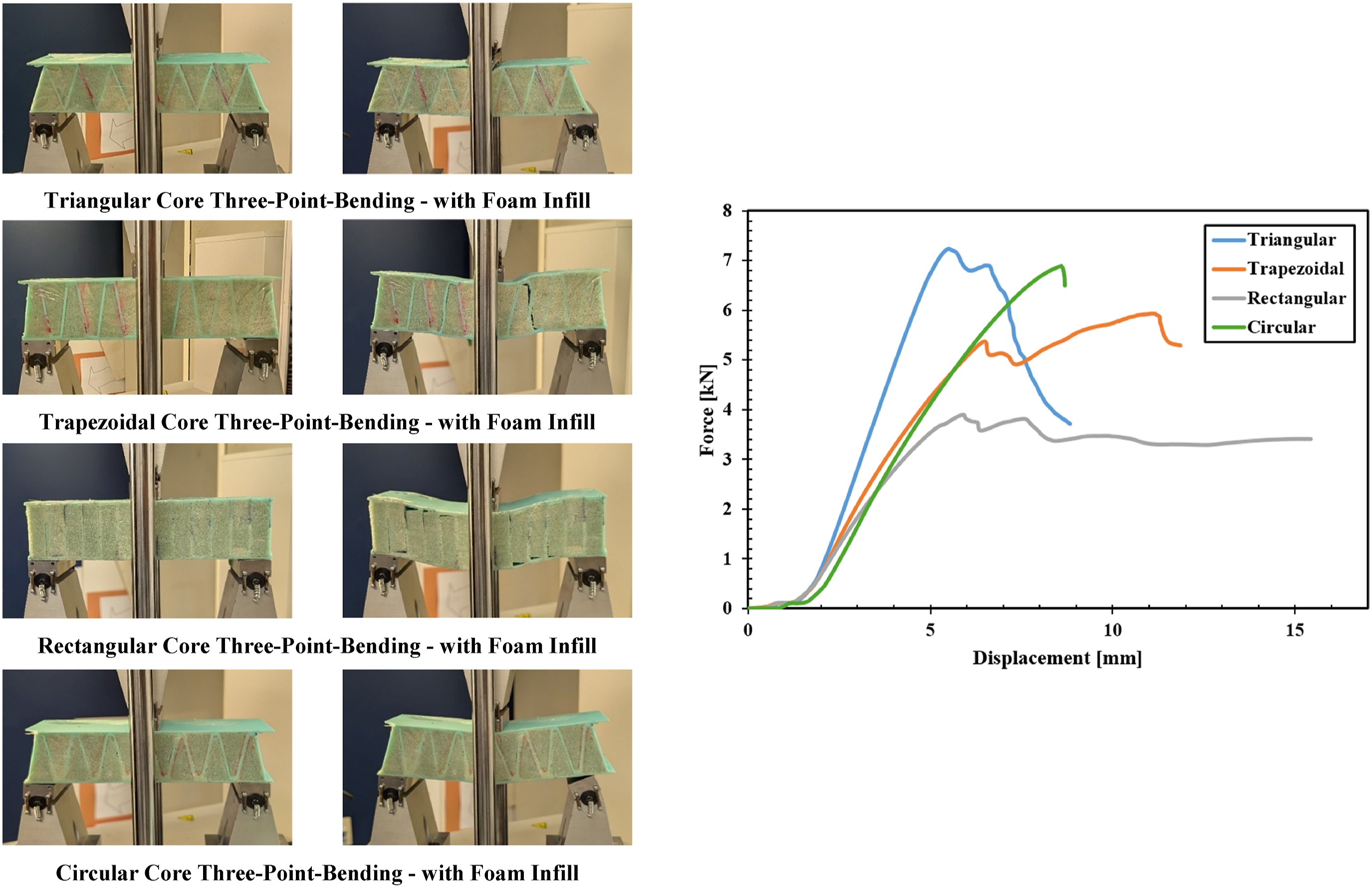
The compression and bending results show that the rectangular core exhibited the highest compressive strength due to its vertical walls, which efficiently transfer compressive forces and ensure even load distribution. However, it performed poorly under bending loads, as the relatively short vertical supports contributed to global deformation instead of local buckling. Despite its lower flexural capacity, the rectangular core provided a more controlled, gradual response under bending. The triangular core, while weaker under compression due to stress concentration at sharp angles, performed better in bending. The angular design hindered load transfer under compression, leading to local buckling, but the diagonal walls provided better bending resistance. Localized failure in the triangular core resulted in more controlled damage but less energy absorption compared to other geometries. Both the trapezoidal and circular cores exhibited good compressive strength. The trapezoidal core concentrated stress at the joints and was more prone to buckling, whereas the circular core demonstrated better bending performance due to its smooth, curved design, which helped distribute stress more evenly. Both cores are suitable for applications requiring a balance of compressive and bending strength, with the circular core performing slightly better under bending loads.
The addition of foam infill enhanced the compressive and flexural capacity of the panels by increasing load distribution and reducing local buckling. The foam also improved energy absorption, making the panels more resilient. With a 217%–345% increase in compressive strength and a 177%–267% increase in flexural strength, the performance of the panel significantly improved with only a minimal weight increase of 32.5% and 40%, respectively. Figure 13 illustrates the enhanced performance of the foam-filled panels through a comparison of the increase in load capacity and weight. Design selection should consider the trade-off between increased mechanical performance and added weight: foam-infilled panels are recommended for applications where load-bearing capacity is critical and a moderate weight increase is acceptable, while hollow core panels are preferable when minimizing weight is the primary concern. Comparison of the percent increase in force and weight under compression and bending.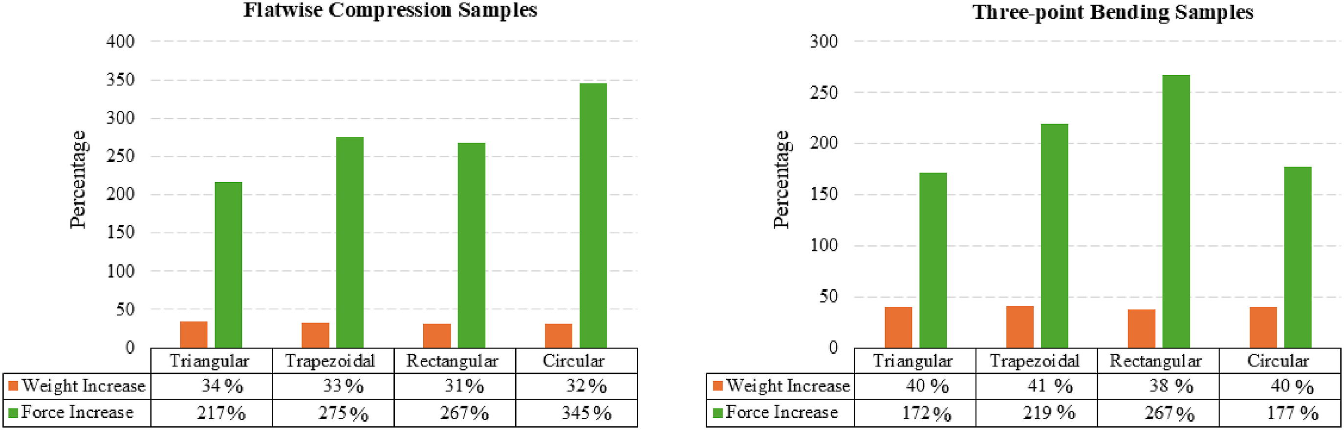
Finite element model verification
Numerical models were developed to facilitate the analysis and optimization of the corrugated core panels. To ensure the accuracy of the models, they must first be verified using the experimental results. Figure 14 presents each corrugated core sample under 1.5 mm deformation, along with the compression force versus displacement curves derived from both the numerical analysis and experimental data. The finite element analysis (FEA) results demonstrate strong agreement with the experimental data regarding the maximum compression force. Similar to the experimental results, the curves included a linear-elastic region followed by non-linear plastic deformation and buckling of the core. However, unlike the experimental results, the FEA curves exhibit a constant force response after the onset of buckling. This behavior is due to the exclusion of post-failure damage mechanisms in the numerical model. This simplification was made to optimize simulation time, as the goal was to identify the load capacity before buckling failure rather than investigate damage progression. Stress distribution illustrations and force-displacement curves for each sample under compression.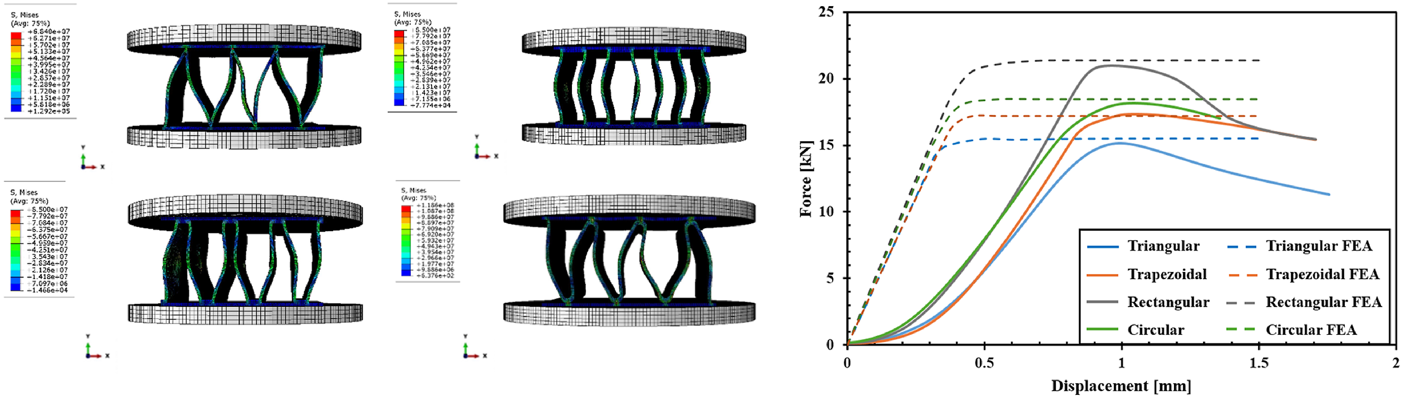
Figure 15 shows each corrugated core sample subjected to 10 mm of deformation, while the rectangular sample was further deformed to 20 mm. The figure also presents the force-displacement curves from both the numerical analysis and experimental data for the three-point bending test. The force-displacement curves obtained from finite element analysis (FEA) demonstrated close agreement with the experimental results for the triangular and circular core panels. These validated models provide a reliable framework for exploring the influence of various geometrical parameters on panel performance. Stress distribution illustrations and force-displacement curves for each sample under bending.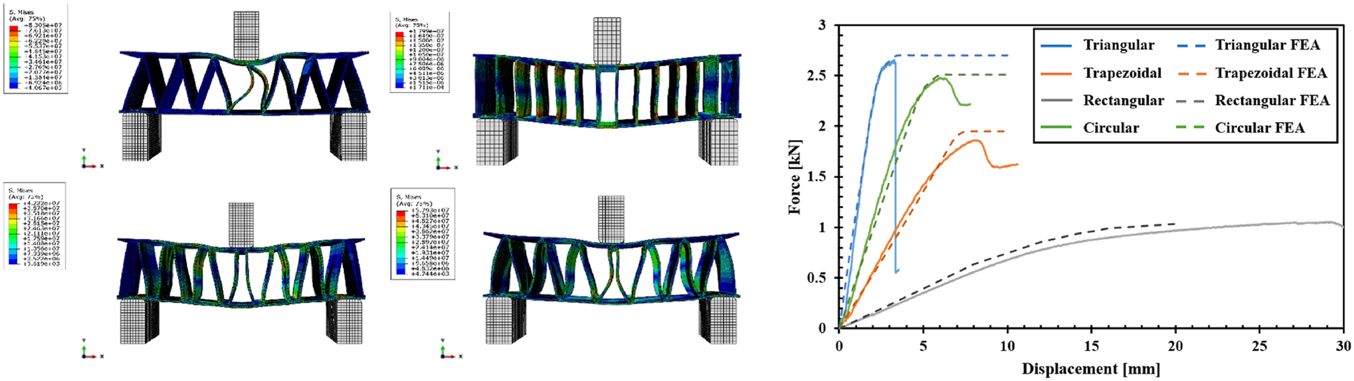
Effect of geometrical parameters on mechanical performance
The finite element models developed in this study facilitate the optimization of corrugated core panel designs by enabling precise refinement of key structural parameters such as core wall thickness, skin thickness, corrugation angle, and the number of corrugations. Among the geometries analyzed, circular and trapezoidal cores demonstrated superior mechanical performance, whereas rectangular and triangular cores exhibited reduced strength under certain loading conditions. As a demonstration of the potential of the model for future parametric investigation, the influence of core wall thickness and corrugation angle on the compressive performance of circular core panels was systematically evaluated through numerical analysis.
Effect of wall thickness on compressive performance
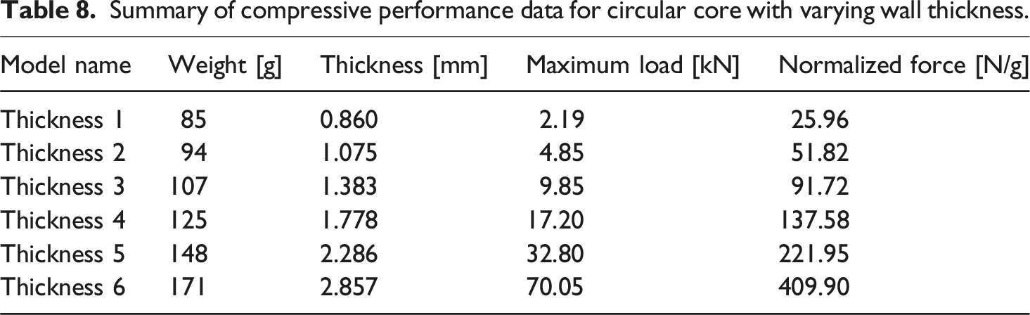
The wall thickness of the circular core panel was systematically varied in 25% increments starting from an initial design of 1.78 mm, as shown in Figure 16. Surface modeling techniques were employed to achieve precise modifications without altering the overall geometry, while the core height was adjusted to maintain a consistent sandwich panel thickness of 2 inches (50.8 mm). To ensure that the observed changes in mechanical performance were solely due to variations in wall thickness, the surface contact area and radius between the core and face sheets were held constant. Increasing the wall thickness enhanced compressive strength and stiffness by promoting more uniform load distribution and reducing stress concentration. However, this improvement was accompanied by increased weight, which may be a limitation in weight-sensitive applications. Finite element analysis results shown in Table 8 revealed that each 25% increase in thickness doubled the load-carrying capacity up to approximately 2.2 mm, with a corresponding weight increase of 10%–15%. Furthermore, as the wall thickness increased, the failure mode transitioned from local buckling to compressive crushing. Thus, while greater wall thickness improves structural strength, its application must be balanced against weight constraints. Maximum normalized compressive force as a function of cell wall thickness. Summary of compressive performance data for circular core with varying wall thickness.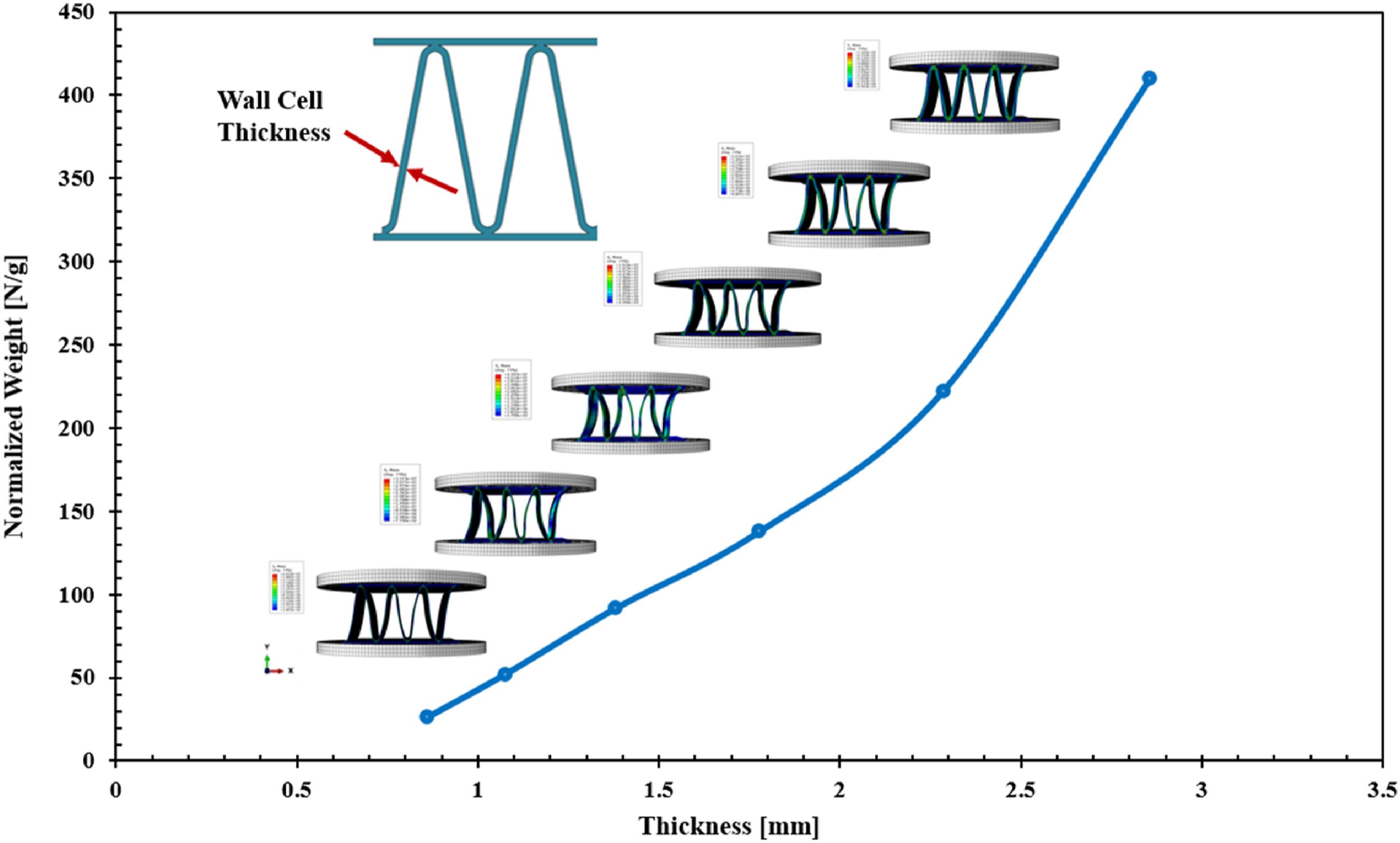
Effect of corrugation angle on compressive performance
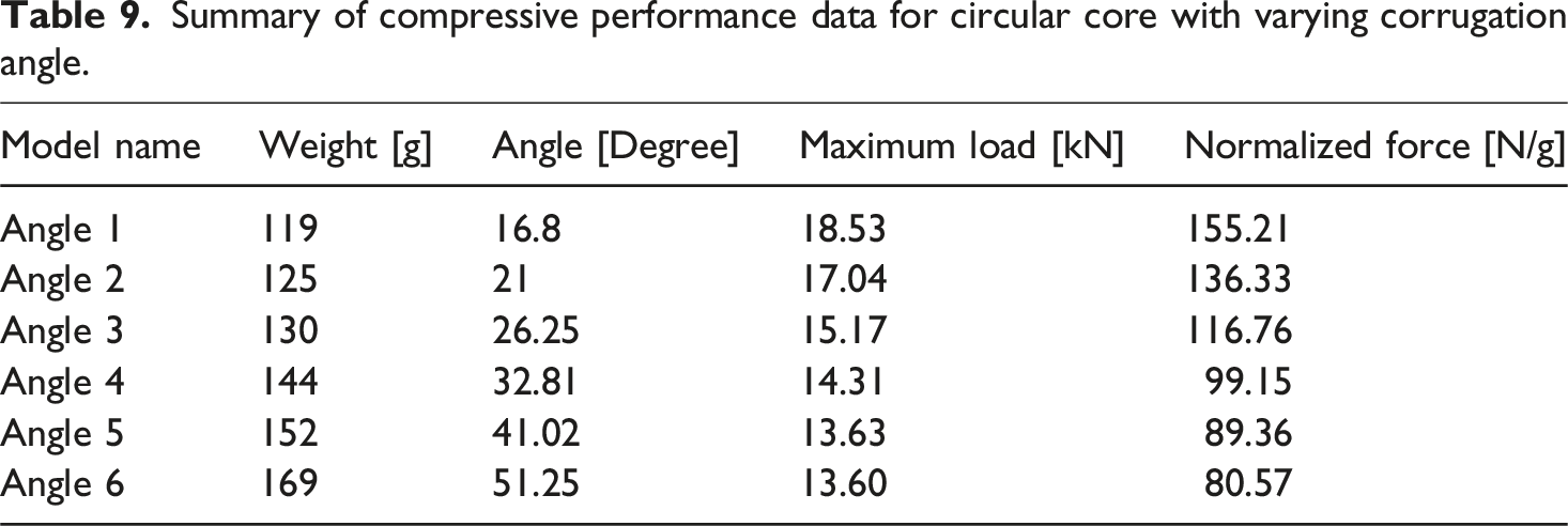
This section examines the influence of the corrugation angle of the circular core on its compressive performance. As shown in Figure 17, the initial core design featured a corrugation angle of 21°, which was systematically varied in 25% increments to evaluate its effect on mechanical behavior. To isolate the impact of the corrugation angle, other geometrical parameters, such as the radius of curvature and the number of corrugations, were kept constant. Adjustments to the corrugation angle necessitated changes in panel length, resulting in larger face sheets and a corresponding increase in weight. However, this increase had only a minor effect on the compressive performance of the panel. Increasing the corrugation angle generally reduced the ability of the core to efficiently distribute compressive loads, leading to lower stiffness and greater susceptibility to buckling failure. Conversely, smaller corrugation angles create a steeper, more densely packed core structure, enhancing compressive load resistance and overall structural performance. Finite element analysis results shown in Table 9 demonstrated that a 25% increase in the corrugation angle led to a 10% reduction in load capacity up to 25°, with an additional 5% reduction up to 40°, beyond which the capacity remained stable. Maximum normalized compressive force as a function of corrugated angle. Summary of compressive performance data for circular core with varying corrugation angle.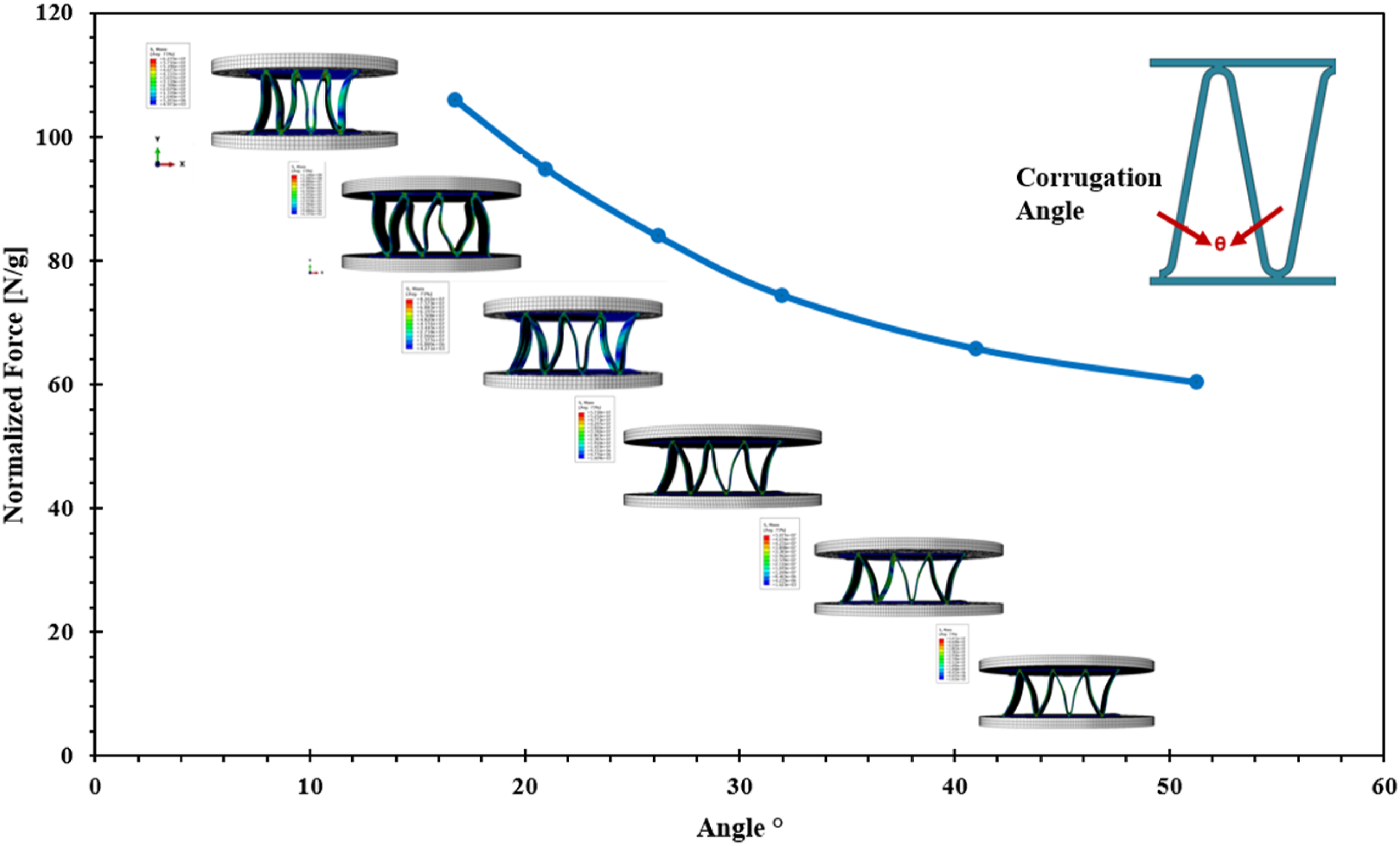
Conclusions
This study methodically evaluates the mechanical performance of 3D-printed corrugated core sandwich panels with triangular, trapezoidal, rectangular, and circular core geometries under flatwise compression and three-point bending tests. The results indicate that circular and trapezoidal cores exhibit strong performance in both compression and bending, whereas the rectangular core demonstrates superior compressive strength but limited flexural capacity. Conversely, the triangular core performed well in bending but exhibited low compressive strength. These findings highlight the critical role of core geometry selection based on the specific loading conditions encountered in structural applications.
To further enhance performance, the corrugated core panels were filled with recycled polyethylene terephthalate (R-PET) foam, and their effect on compressive and flexural properties was investigated. The addition of R-PET foam significantly improved both load-bearing capacities with only a minimal increase in weight. Finite element models for flatwise compression and three-point bending were developed for all core geometries using ABAQUS, and the simulations showed close agreement with experimental results, providing insights into stress distribution, the influence of cell wall thickness, and the impact of corrugation angles on panel performance. These findings reinforce the experimental observations and emphasize the potential of hybridized corrugated core sandwich panels for lightweight, high-performance structural applications.
Such structures are particularly relevant to the aerospace, marine, and construction industries, where a combination of mechanical efficiency and thermal insulation is required. PET foam sandwich panels are already employed in practical settings such as trailers, modular enclosures, and poultry housing. With improved load-bearing capability, the range of potential applications can be extended to include aerospace interior panels, marine flooring, and automotive components, where weight reduction, insulation, and structural efficiency are critical.
Looking ahead, the long-term performance of materials such as PLA and PET may be influenced differently by environmental factors, including moisture, UV exposure, and cyclic loading. Future studies should evaluate the impact of these conditions on material degradation to ensure the durability and reliability of corrugated core sandwich panels in real-world applications.
Footnotes
Acknowledgments
I would like to express my sincere gratitude to Mr Moghaddar, the general manager of ICP Inc., for his generous contributions of materials and for the valuable discussions that have greatly enriched this study.
Funding
The authors disclosed receipt of the following financial support for the research, authorship, and/or publication of this article: This work was supported by the Natural Sciences and Engineering Research Council of Canada (NSERC) and Innovative Composite Products (ICP) Inc. through the Alliance program.
Declaration of conflicting interests
The authors declared no potential conflicts of interest with respect to the research, authorship, and/or publication of this article.