
Abstract
Sandwich panels are the fundamental structural element in a wide range of applications, including in satellite primary structures. While sandwich constructions are very efficient, their complex multi-material assembly leaves room for further optimisation of the core volume and improvement in the integration phase. One key technology that can enable the transition to multifunctional sandwich panel cores tailored to certain applications is the additive manufacturing (AM) of satellite primary structure sandwich panel cores. This paper investigates the feasibility of replacing the baseline Aluminium honeycomb core with a core printed out of AlSi10Mg through Powder Bed Fusion. Sandwich panels with carbon fiber-reinforced plastic (CFRP) facesheets and printed honeycomb cores as well as fully printed corrugated panels are produced and tested under three point bending (3PB) and compression as part of the EU funded ReDSHIFT project. The Instron 5560 (3PB) and 4204 (compression) are used to perform the experiments that follow the ASTM C393-11 and C365 standards. When compared against the baseline CFRP-AL panels, the 3D printed honeycomb cores carry up to twice as much load per unit mass in bending and four times as much in compression, while also being stiffer. The fully printed corrugates samples are weaker than the honeycombs, but in conjunction with the honeycomb geometry may present a promising avenue for developing multifunctional cores. While limitations with current metal printing technology prevent AM cores from matching the mass of baseline designs, the superior specific performance and geometrical freedom make printed cores a promising design alternative.
Keywords
Introduction
Additive manufacturing of sandwich panels
Although sandwich constructions have been widely used for decades in structural applications, including in the context of satellite primary structures, their design and manufacturing philosophy has not evolved significantly. By design, sandwich constructions have very light cores and stiff facesheets and especially in the case of CFRP faces and aluminium cores very efficient designs can be achieved. However, the structural performance of baseline sandwich panels can be further improved by simplifying their complex manufacturing process and multi-material assembly which is shown in Figure 1 below. The main parts of a standard honeycomb sandwich panel.
1
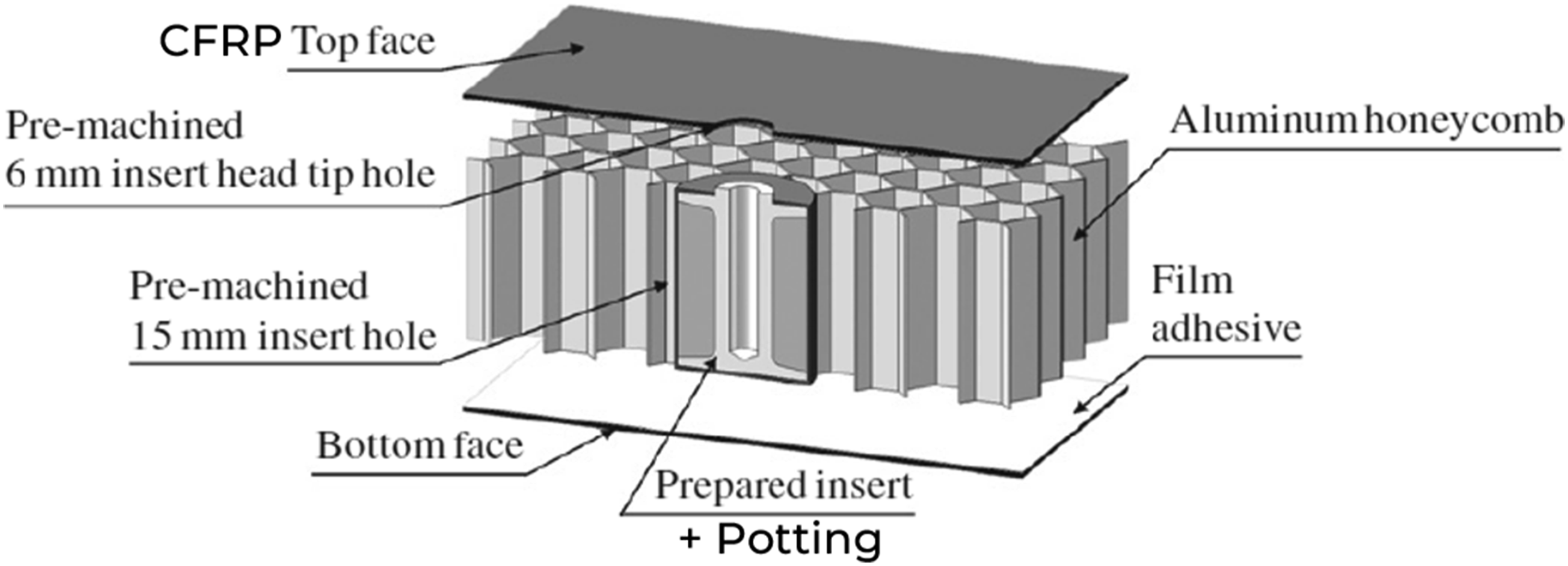
The manufacturing of Aluminium honeycomb cores is either performed by bending Aluminium sheets, strip bonding them and pulling them apart to create the expanded panel or by running Aluminium sheets through a gear press to obtain the desired corrugations which are then welded together. 2 Both methods introduce anisotropy in the structure because cell walls parallel to the ribbon direction have twice the wall thickness compared with the rest.
The way the panel core volume is used can be improved to have a more optimised integrated core and insert solution. Previous work by the authors has investigated the concept of 3D printing sandwich panel inserts as part of fully printed cores,
3
and this paper aims to provide more information on the fundamental structural performance of the additively manufactured panel cores themselves. The idea of 3D printing sandwich panel type structures is not new and it has been investigated previously, mostly in the context of thermoplastic materials, honeycomb geometries and lattice structures. The research on 3D printed honeycomb cores has focused solely on thermoplastic materials such as VeroWhitePlus,4,5 ABS
6
and PLA
7
and it investigated topics such as compression energy absorption,5,7 natural frequency optimisation
4
and the variation of mechanical properties with the cell size and wall thickness.
6
What these studies have in common is that they lead to honeycomb geometries with improved structural performance through small design changes that can only be achieved through 3D printing. Some of these designs are shown in Figure 2.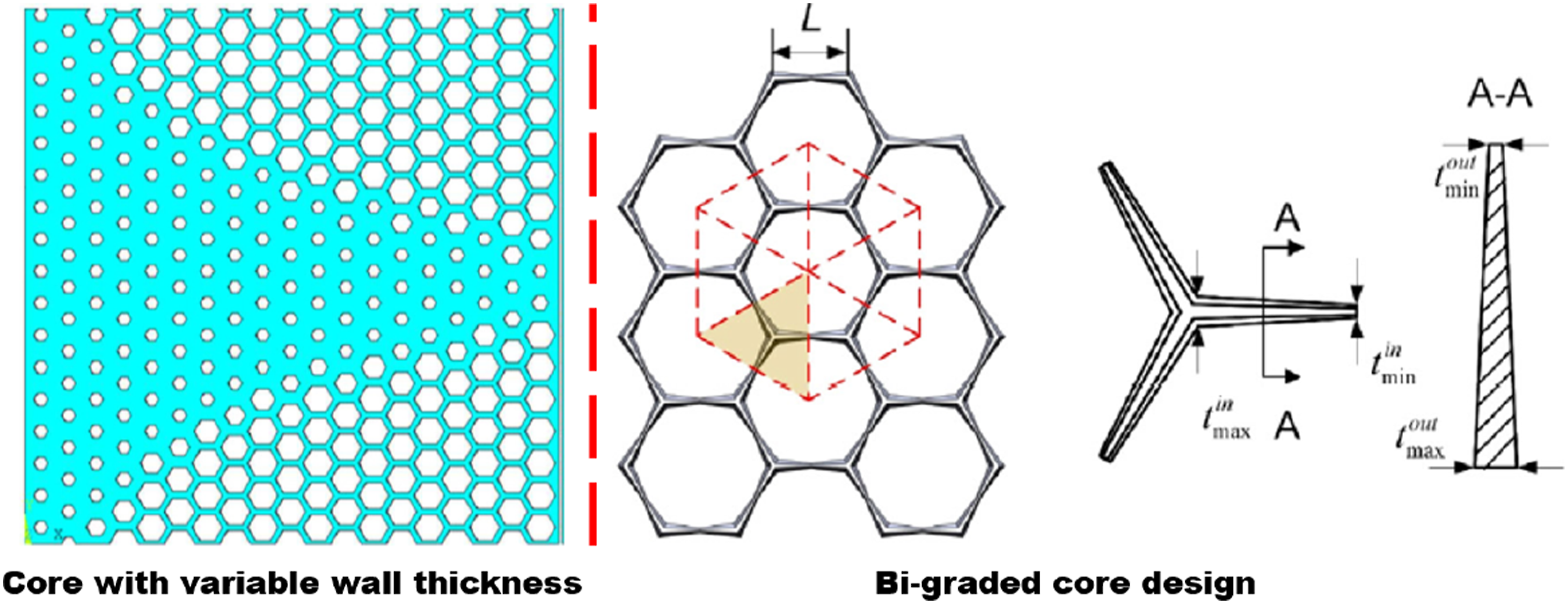
In, 4 varying the wall thickness of the honeycomb cells while maintaining the sample mass achieves a 38% increase in the fundamental frequency of the geometry. In 5 varying the wall thickness of the honeycomb cell edges increases the specific energy absorption of the geometry by up to 172%, while in 7 implementing a bi-graded cell design leads to a 46% improvement in the same parameter compared with the baseline geometry. These are promising results that demonstrate the performance improvements that are enabled by additive manufacturing (AM). However, no research covering the structural properties of metal 3D printed honeycomb sandwich panels was identified.
Lattice structures have been studied in the context of four different material classes: resins, thermoplastics, ceramics and metals. Research on thermoplastics, 8 resins9,10 and ceramics 11 focuses on the bending and compression behaviour of a range of lattice geometries. On the metal printing side, Ti-6Al-4V electron beam melting (EBM) 12 and 316L Stainless Steel Powder Bed Fusion (PBF) 13 printed lattices were investigated and modelled. These papers provide a basis for evaluating the mechanical properties of metal 3D printed thin-walled lattice structures, but they focus on high density materials which are not viable options for light sandwich panel cores. No previous studies tackle the mechanical performance of honeycomb or lattice structures printed out of the lower density AlSi10Mg material.
The challenge of keeping the satellite primary structure light while implementing 3D printing to enable more optimised designs is also translated into the need for printing thin walls and for understanding their mechanical properties. Properties of thin-walled AM elements have been studied previously for both thermoplastic and metal materials. In both cases, based on studies performed on 1 mm thick samples made either from fused deposition modeling (FDM) PLA14,15 or laser powder bed fusion (LPBF) Ti6Al4V,16,17 a thinner wall leads to more deviation from the design wall thickness and to more warping. Furthermore, metallic structures with wall thicknesses well below 0.5 mm for lightweight sandwich panels were addressed in 18 , where a novel approach was introduced for printing components down to 0.1 mm.
The difference between the designed and the fabricated wall thickness of LPBF AlSi10Mg was also recently investigated. 19 For samples between 0.3 mm and 3 mm thick, the fabricated wall thickness of AlSi10Mg is smaller than the design thickness, but no correlation with material properties was investigated apart from a study on microhardness which shows no clear trend. The tensile strength variation for sample thickness between 0.5 mm and 5 mm was studied for Ti6Al4V specimens printed through EBM and the 0.5 mm sample had a 30% lower ultimate tensile strength (UTS) compared with the 1 mm sample. 20 These studies demonstrate the challenges of printing thin-walled load bearing structural elements out of various metals.
Overall, 3D printing the honeycomb core could potentially lower the time, cost and manufacturing complexity by replacing a multi-step process with one that only involves one printer and the technicians to set it up, while also providing additional design freedom which could lead to novel multifunctional geometries.
Multifunctional structures
Adding other functions into satellite sandwich panel structures in order to improve the integration of satellite platforms has been recognised as one of the top five technical challenges in the 2012 NASA Technical Roadmap, 21 and the National Research Council (NRC) review of this roadmap recommended it as the top priority in the area. The relevance of multi-functional structures (MFS) was reiterated in the 2015 NASA Technology Roadmap 22 as well as in the 2015 NASA Small Business Innovation Research (SBIR) Solicitation. 23
Since their first implementation over 40 years ago, multifunctional satellite structures have transitioned from integrating electronics, avionics harnessing and batteries24–28 to adding functionalities such as thermal management, radiation shielding, debris shielding and smart structures.29–31 Two of the concepts that bring together some of the most cutting edge multifunctional aspects such as printed cable harnesses, embedded thermal sensors, fibre optical sensors, vibration control systems or inserts that can transmit data and energy were presented at the 2021 European Conference on Spacecraft Structures, Materials and Environmental Testing (ECSSMET). These two concepts have been manufactured and tested by Invent GmbH 30 and by the DLR. 31
In spite of the high priority of putting MFS on flight hardware, very few such components have flown32,33 and there is still a significant gap to mass producing and integrating them on a large scale. One of the issues is related to the assembly, integration and verification (AIV) of these systems. When integrating electronic components inside a panel they become less accessible, while also posing safety issues. 27 The other major problem is the complex manufacturing that goes into producing such panels, especially when using standard subtractive manufacturing techniques. For example, the panel developed in 30 went through several manufacturing steps such as CFRP curing, CFRP injection, GFRP injection, bonding, CNC milling and insert potting, with similar complexity for the panel developed by the DLR. 31 With the development and continual maturation of AM methods, potential opportunities exist to create efficient multifunctional structures that avoid many of the limitations that have previously been identified.
In the past decade, the focus has partly shifted to using 3D printing in the design of MFS and a representative project for this research direction is multiSat, which ran between 2016 and 2018. It looked at integrating both passive (heat transfer, radiation and impact shielding) and active (vibration reduction, transmission of data and electric energy) functions into the primary structure.
34
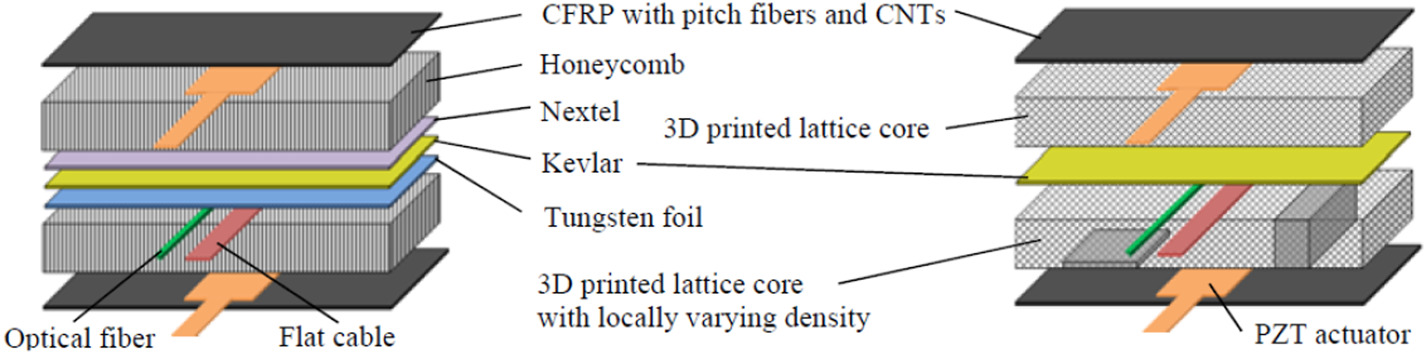
Two multifunctional concepts were produced, both depicted in Figure 3, with the second employing a 3D printed lattice core with varying cell densities for thermal and protective purposes. These concepts demonstrated aspects such as vibration reduction by shunt damping, transmission of data and electrical energy and improved shielding performance compared with classic honeycomb panels.35,36 The two multifunctional concepts proposed by multiSat.
35
Corrugated geometries
Bringing together the idea of 3D printing sandwich cores to improve the structural performance and to add multifunctionality to the panel, makes corrugated geometries of interest for this study. Corrugations are efficient in absorbing the energy coming from high velocity impacts37,38 and can potentially improve the orbital debris shielding performance of honeycomb sandwich panels. In addition, the combination of a honeycomb core with a corrugated core (which is referred to as hybrid) has been studied recently at Xi’an Jiaotong University in China.39,40 A series of hybrid designs produced through subtractive manufacturing was investigated and it was determined that combining a corrugated core and a honeycomb core can actually enhance the overall specific performance in both compression and 3PB. However, the limitations of subtractive manufacturing were exposed as in 3PB the hybrid sample underperformed due to bonding issues. For a 3D printed core there would be no adhesives needed, so the true potential of the design may be attained.
This paper presents some of the experimental results from the EU funded ReDSHIFT project 41 which address the gaps identified in developing novel satellite structures. Sandwich panels with 3D printed AlSi10Mg cores and CFRP facesheets are produced and loaded in bending and compression. These panels are compared against baseline sandwich structures. In parallel, a set of fully printed corrugated structures is tested under the same loading conditions to assess the structural behaviour of a geometry that could enhance other properties of the satellite primary structure. These structures have the advantage of being relatively simple monolithic structures and therefore the experimental results are useful for the purpose of data comparison.
Sample selection
Honeycomb (HC) 3PB and compression experimental samples.
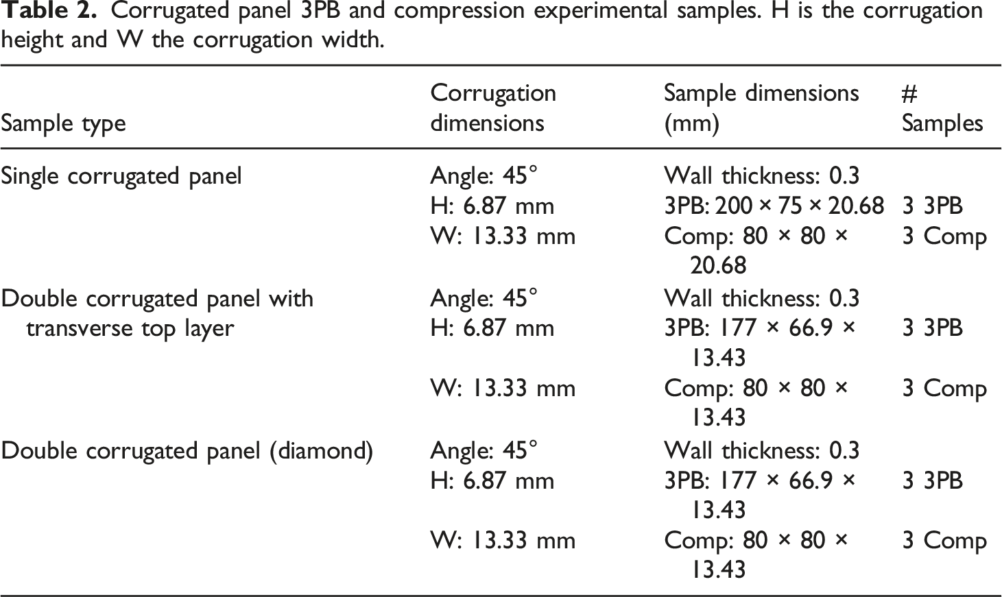
Corrugated panel 3PB and compression experimental samples. H is the corrugation height and W the corrugation width.
Acronyms for the ReDSHIFT experimental samples.
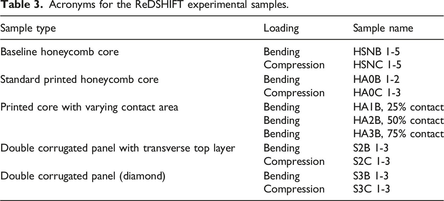
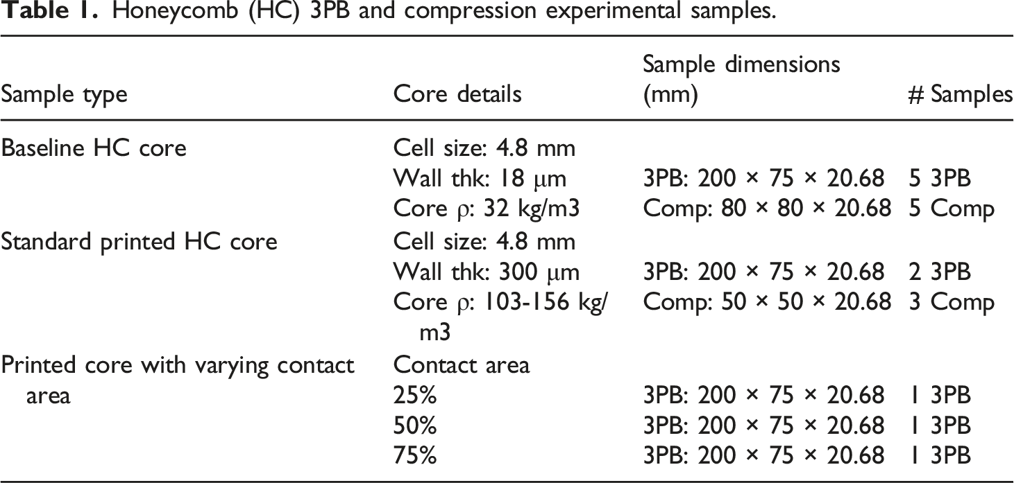
Table 1 outlines the honeycomb samples consisting of 18 different test specimens. The first honeycomb sample type was the baseline CFRP sandwich panel which represents the current standard in satellite primary structures. Two variants of this sample type were manufactured with different overall dimensions to be subjected to 3PB and compression load cases. Five repeat samples of each were tested. The second honeycomb panel type had a 3D printed AlSi10Mg honeycomb core with the same cell size as the baseline core. This core was printed at a wall thickness of 300 µm. Two variants of this sample type were again manufactured with different overall dimensions to be subjected to 3PB and compression load cases and they can be seen in Figure 4. Fewer repeat samples had to be used for this sample type due to the project budget constraints. Honeycomb test specimens (left) and the honeycomb cell geometry with increased adhesive contact area (right). Note that HA0B1 and HA3B are shown without the facesheets.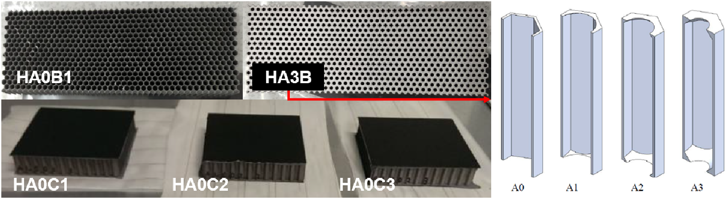
The third honeycomb panel type consisted of a modified core which varied the available contact area with the adhesive and facesheets. Looking at the right of Figure 4, the contact area is given by the top or bottom face area of the honeycomb core in contact with the top or bottom CFRP facesheets. It was used to assess how a simple design change can further improve the mechanical performance of the sandwich panel. This geometrical variation is detailed in Figure 4 and the sample with 75% contact area is shown in the top center of Figure 4.
The facesheets for all honeycomb core samples are 0.64 mm thick TORAY M55 J pan graphite/EX-1515 laminate CFRP, while the baseline honeycomb core is made out of Al 5056 Hexcel. Each sample type and repeat has the same designated name as shown in Table 3. For both the baseline and the printed sandwich panels, the production of the specimens followed similar steps. The top and bottom CFRP facesheets were bonded to the Hexcel or to the printed honeycomb core using Hexcel Redux 312UL adhesive film which has a mass of 100 g/m2. The samples were then vacuum bagged and placed in a thermal vacuum chamber for curing and then they were cut to their final dimensions using a water-lubricated saw with a diamond coated disk.
Table 2 outlines the corrugated samples consisting of 18 more test specimens. Three corrugated geometries are considered: the single corrugation (S1), the double corrugation with a transverse top layer (S2) and the double diamond corrugation (S3). Two variants of each corrugated sample type were manufactured with different overall dimensions to be subjected to 3PB and compression load cases. The three printed corrugated geometries can be seen in Figure 5 after their bending and compression tests. Three repeat samples of each were tested and named as shown in Table 3. The bending and compression samples tested during the ReDSHIFT experimental campaign. Sample cross-sections provided for clarity. Note that S2B and S2C have two layers of corrugations offset by 90°.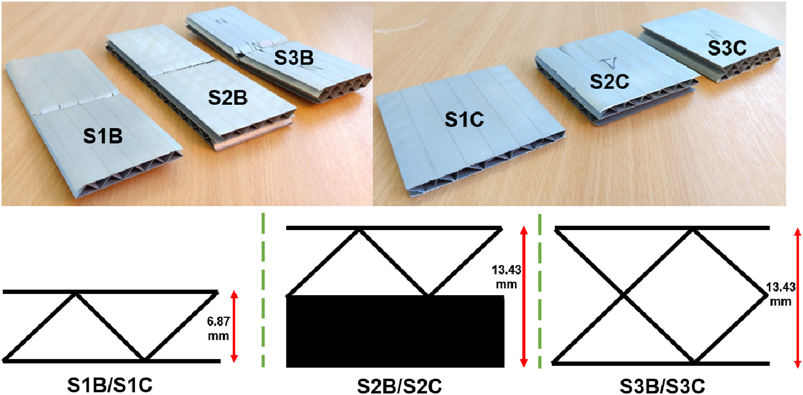
3D printed tensile specimen properties. CV is coefficient of variation.
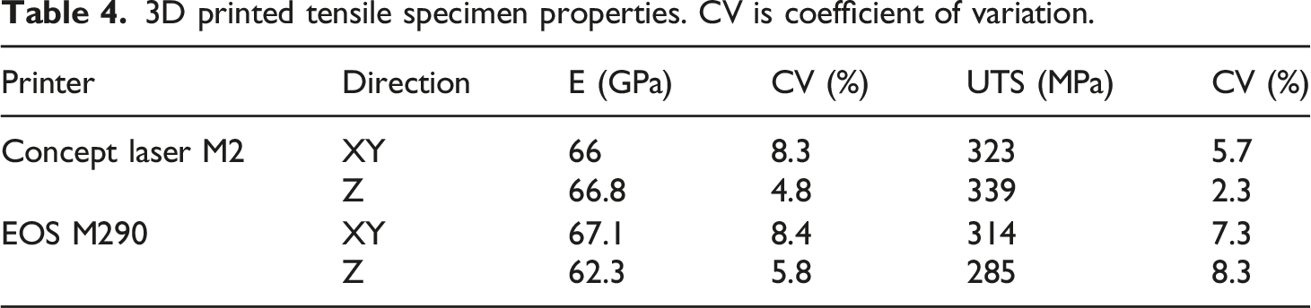
The properties of AlSi10Mg are similar to those of Al5056, which has a Young’s Modulus (E) of around 71 GPa and an ultimate tensile strength (UTS) of 290 MPa. 42 The tensile samples had a designed thickness of 2.16 mm, which is significantly higher than that of the printed honeycomb cores which also feature flaws. It is thus expected that the E and UTS will be significantly reduced in the printed sandwich samples.
Structural performance assessment
Experimental setup
The experimental setup is depicted on the left of Figure 6, with the two loading cases detailed on the right. Experimental configuration (left) and a detailed view of the 3PB and compression setups (right). The 3PB setup is at the top and the compression setup at the bottom.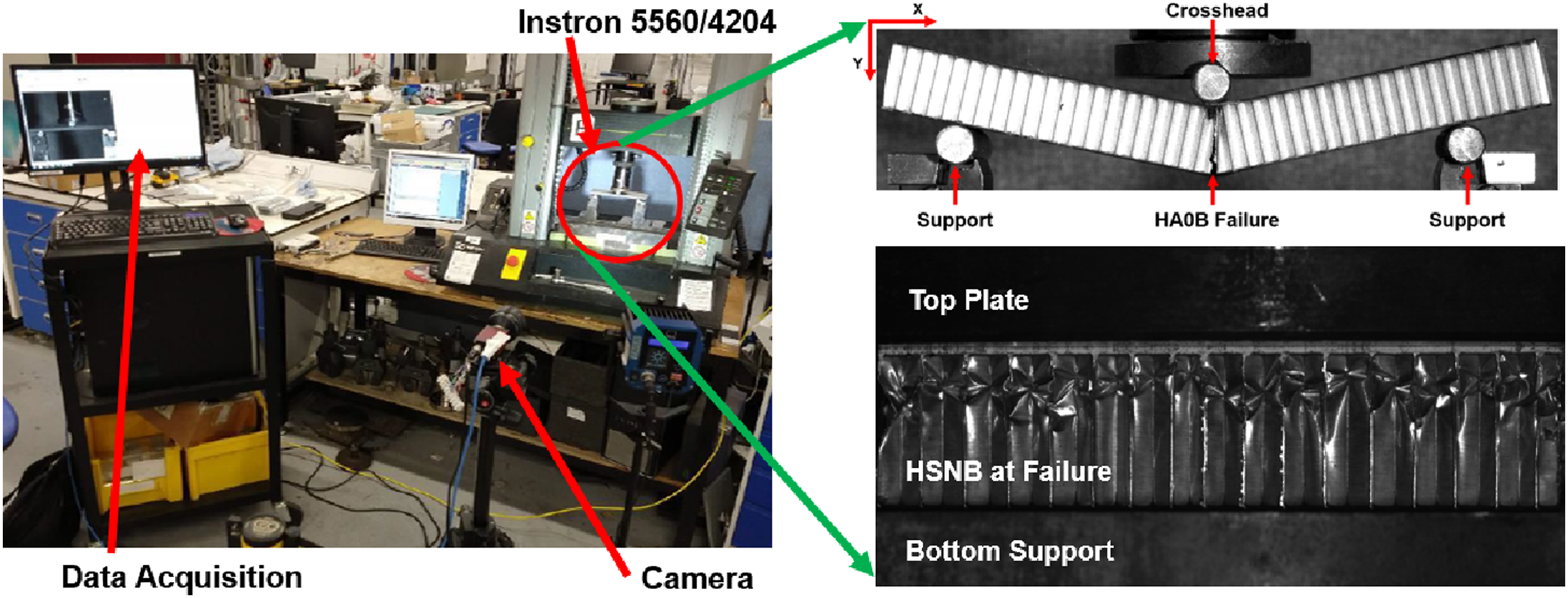
In 3PB, the ASTM C393-11 test standard was followed, which recommends a sample size of 200 mm by 75 mm in plane, with a free span of 150 mm and a facesheet thickness at least 10 times smaller than the core depth. The honeycomb sandwich panels were produced to this precise standard as they have a 150 mm free span. The corrugated samples maintained the length to width ratio recommended by the ASTM standard, but their length was reduced due to cost and printing bed size constraints. As a result, the corrugated bending samples have a free span of 133 mm, while still being in line with the ASTM standard. For the 3PB experiments, the roll pins that apply the load and support the samples have a 12 mm diameter and are free to roll.
In compression, the ASTM C365 standard was followed, which for a honeycomb cell size of 4.7625 mm recommends a minimum test sample dimension of 50 mm by 50 mm in plane, which was complied with.
For all structural experiments, the failure load was reported from the INSTRON load cells in the test machines (INSTRON 5560 for 3PB and INSTRON 4204 for compression) with sampling every 0.1 s. Displacement is captured using image tracking in ImageJ with a frame every 0.2 - 1 s depending on the specific sample and loading case. The loading rate was 6 mm/min for 3PB (as per ASTM C393-11) and 0.5 mm/min for compression (as per ASTM C365). The displacement reported by INSTRON can be inaccurate because it includes the displacement of the machine itself, while point tracking isolates the sample displacement. However, due to the lower sampling rate, the imaging data may miss the true load peaks, whereas the INSTRON provides this data at a higher sampling rate.
Two key sources of error are accounted for in the presented data. The first is due to the variation in load or displacement for similar samples undergoing the same loading scenario. The second is from the displacement variation between several points tracked on the same sample. The latter is used to confirm that point tracking was performed at reliable and robust locations such as the crosshead and the supports where virtually no body displacements occur.
Experimental results
Three point bending
For all samples, the region of interest is the behaviour before failure together with the overall stiffness and strength information obtained from the force-displacement curve. Figure 7 shows the average curve of the experimental force-displacement data for the baseline honeycomb core (HSNB) and the standard printed core (HA0B) in bending together with data for each individual sample. Force displacement curves for HSNB and HA0B under 3PB. Average curves in bold and dotted lines for each individual sample.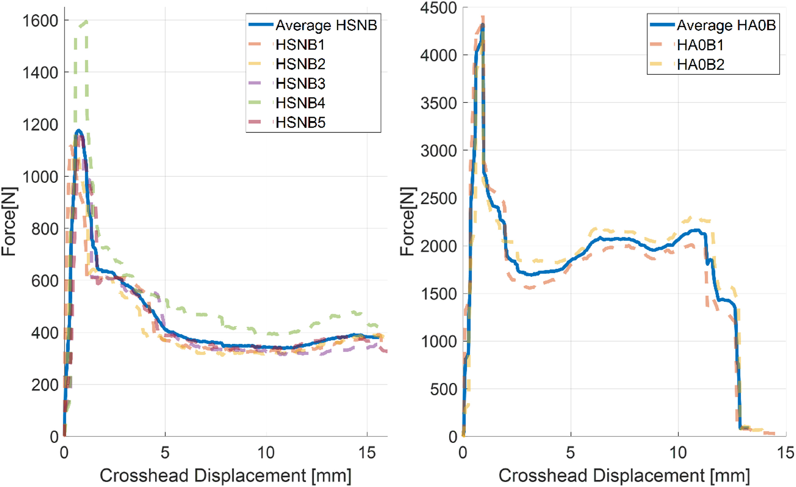
Looking at the initial loading of the two sample types, HSNB has a smoother curve compared to that of HA0B showing a linear elastic behaviour before failure. The printed cores exhibit displacement step jumps during loading, which given the sample defects can lead to the conclusion that HA0B fails sequentially as crack propagate and release energy through a rearrangement of the microstructure within the material, while HSNB has a single energy release at failure. Both HA0B samples and the HA1B - HA3B samples exhibit these step jumps, as shown in Figure 8, demonstrating consistency in terms of the failure mechanism. Force displacement curves for HA1B, HA2B and HA3B under 3PB.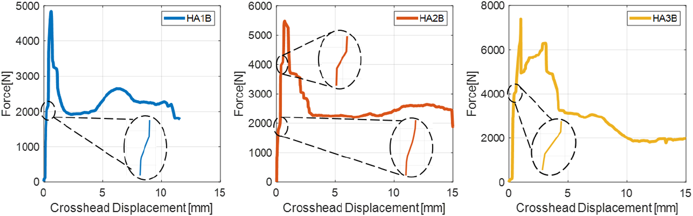
When investigating the failure modes of the baseline and the printed panels, a clear distinction between the two panel types can be observed. Looking at Figure 9, all HSNB samples fail through through buckling of the core under the crosshead. For all five samples the core fails before the top CFRP facesheet and the stress is more localised than in the case of the printed cores. For the printed honeycomb samples, the top CFRP facesheet fails before the core elements. There is no sign of buckling of the core walls, which fail through shear loads applied across the printing direction. In the case of the printed samples, the core is almost over-designed for the facesheets, while for the baseline panel the opposite occurs. Honeycomb samples after failure under 3PB. The difference in failure modes between the baseline panels and the printed panels can be observed.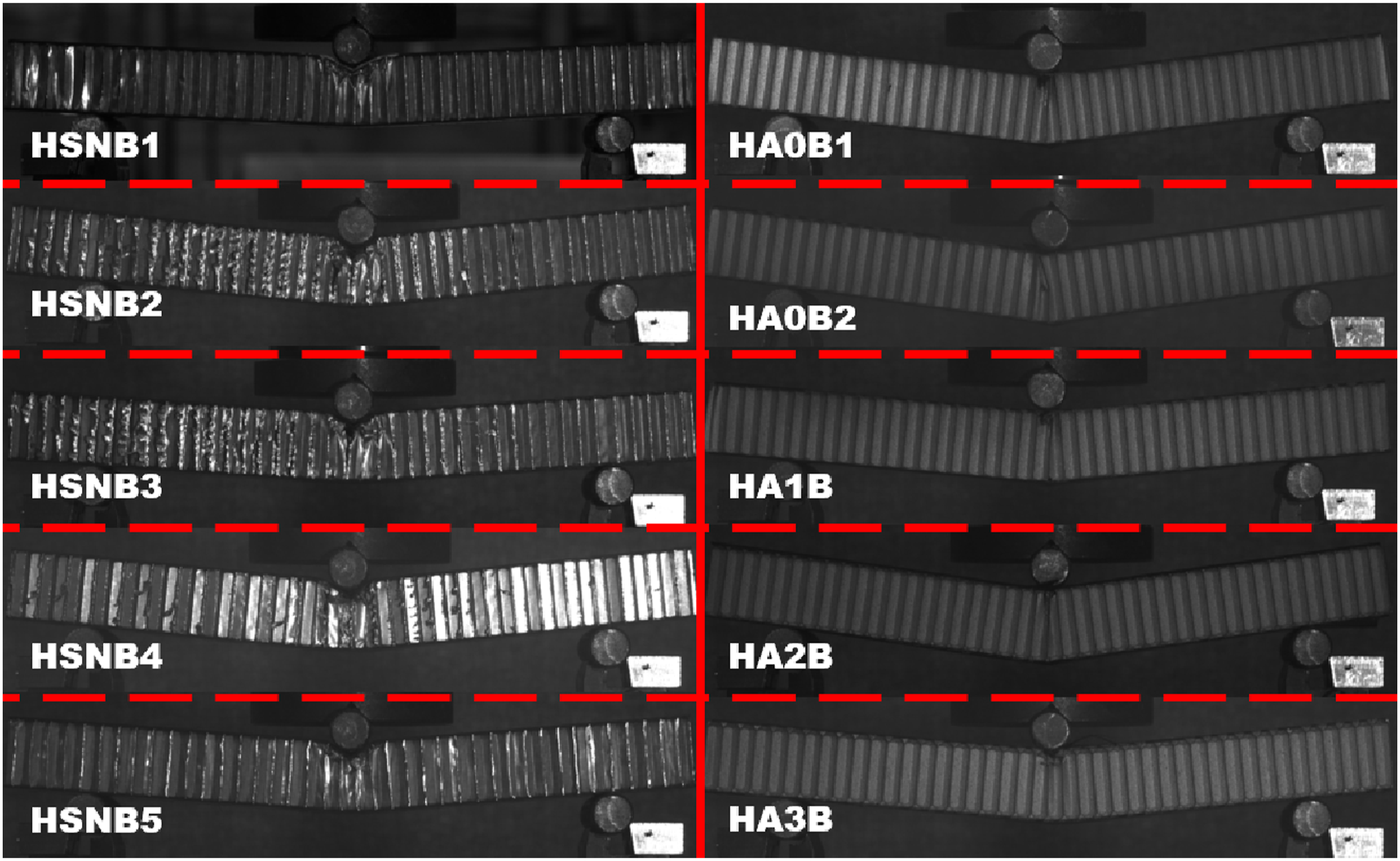
Analysis of the sample failure modes also reveals why HSNB4 is an outlier in terms of the failure load, as observed in Figure 7. For four out of the five baseline panels a single central honeycomb wall buckles and determines the failure of the sample, while for HSNB4 buckling occurs at two honeycomb walls simultaneously leading to an increased failure load.
For the corrugations, the elastic part of the curve is close to linear and does not exhibit the step jumps showed by the printed honeycomb core, as shown in Figure 10. S2B strays the most away from the expected bending force-displacement curve and to better understand its behaviour, this sample type is discussed below. Force displacement curves for the three corrugated geometries under 3PB. Average curves in bold and dotted lines for each individual sample.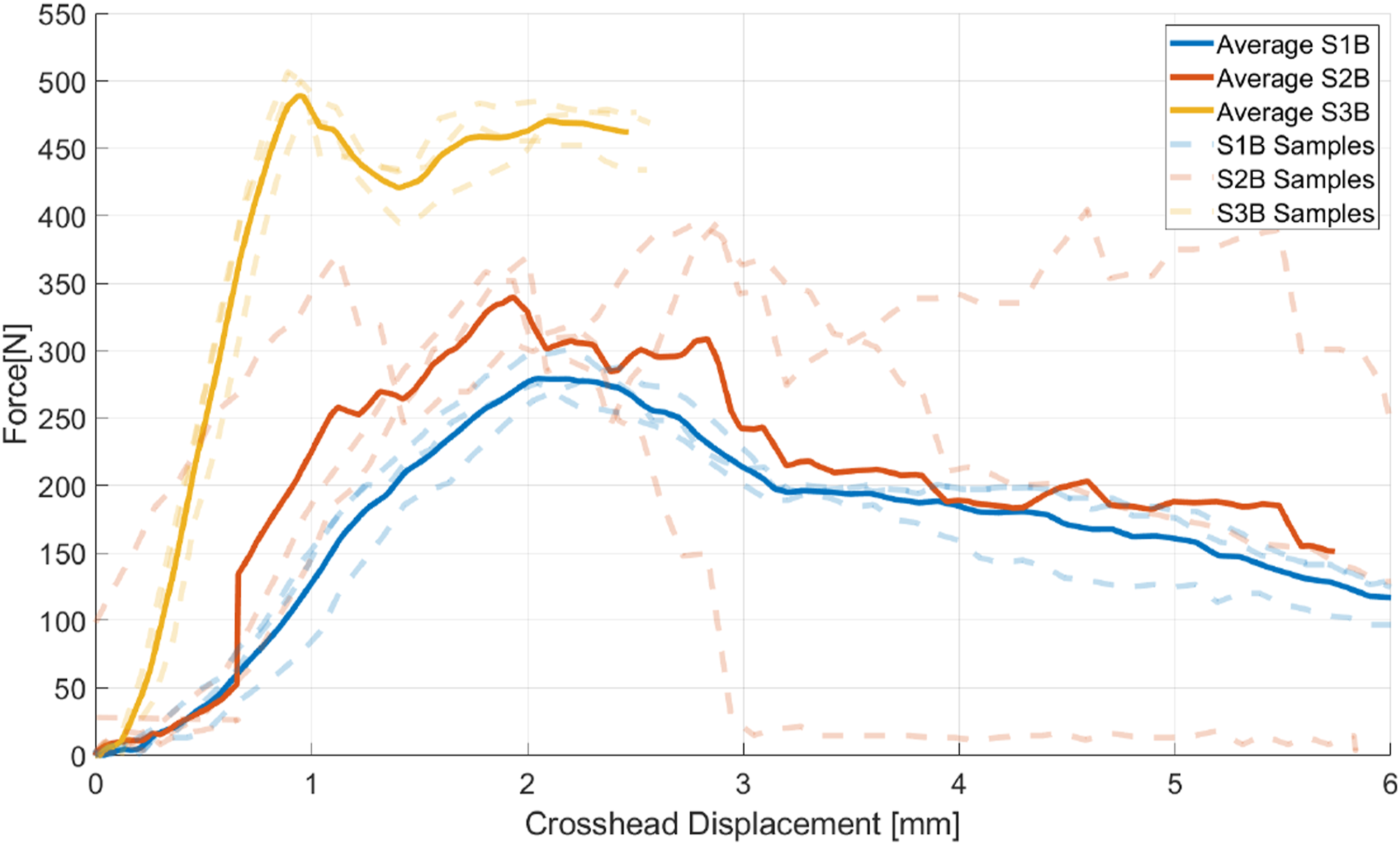
Samples two and three of S2B have several increasing load peaks, while specimen one follows the expected 3PB behaviour with only one definite load peak. Looking at the experimental image sequence in Figure 11, the differences between the three samples can be explained. For S2B2, corrugation walls first fail above one support, then above the other and then the sample fractures close to its centerline. This gives rise to three individual peaks as densification takes place repeatedly. Similarly, for S2B3, corrugation walls first fail close to one support and then the sample fractures along the centerline. Finally, S2B1 fails along the center and thus has a single load peak. Local defects and sample position with respect to the supports change the force - displacement curve significantly and S2B1 is the only specimen which fails only under the crosshead as expected. The failure stages of Specimen two of the corrugation type S2B.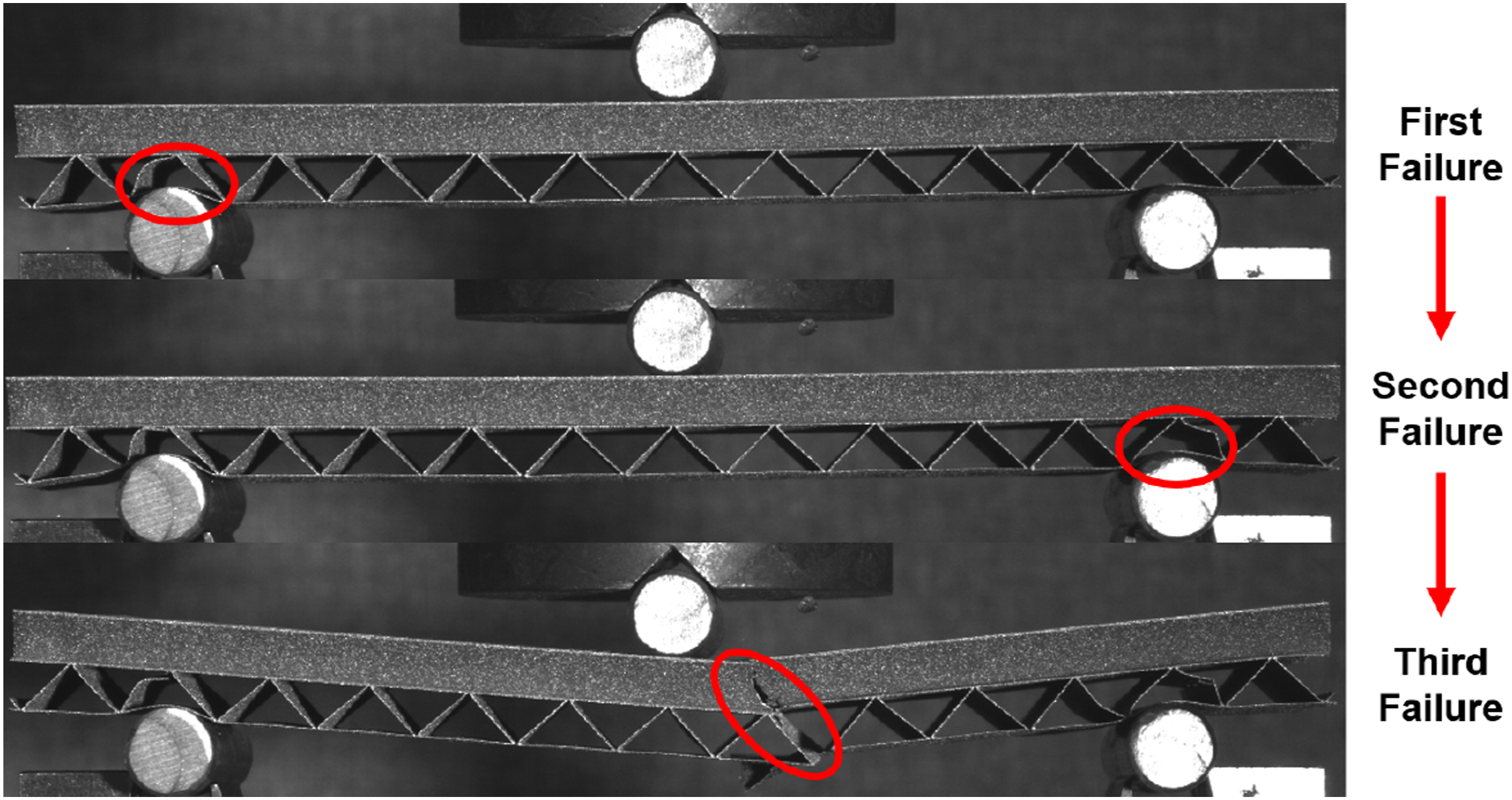
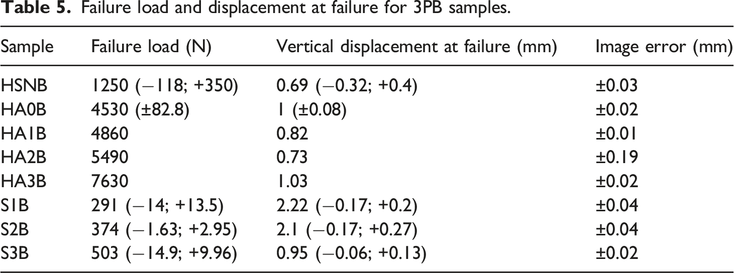
Failure load and displacement at failure for 3PB samples.
Specific strength and specific stiffness for 3PB samples.
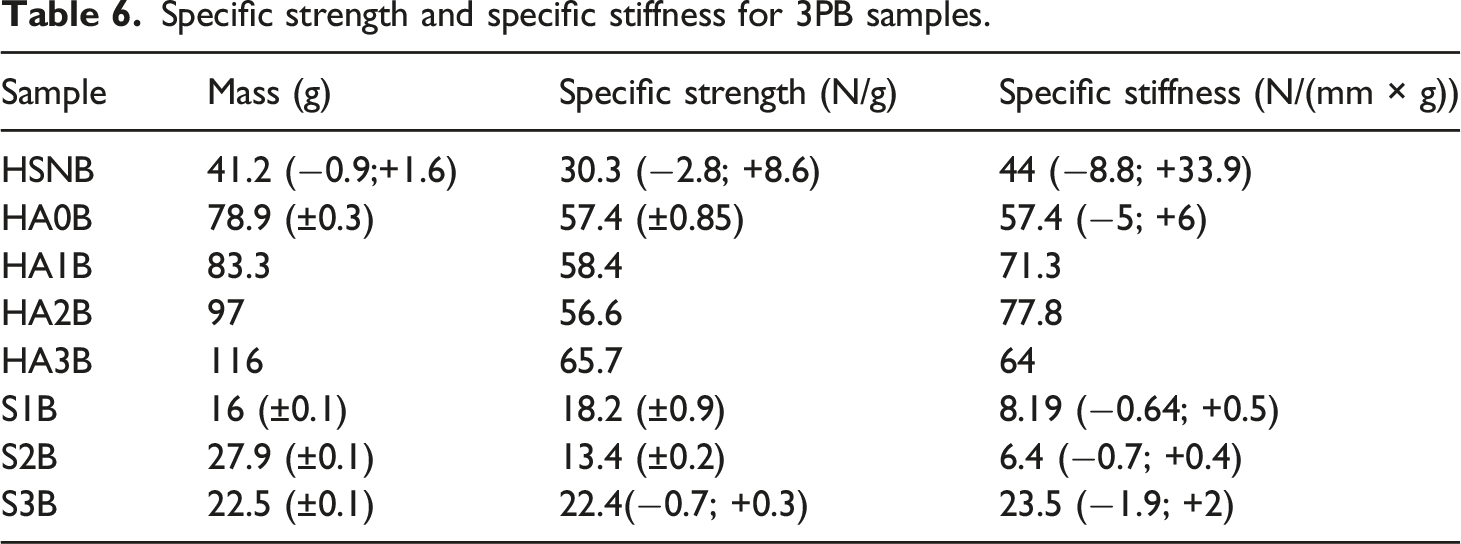
The standard printed sample, HA0B, has a superior specific strength and stiffness compared to the baseline panel, HSNB. In the case of HSNB, the experimental outlier HSNB4 pushes the upper range of the specific strength and stiffness values beyond the expected behaviour for this sample type. When varying the adhesive contact area, both strength and stiffness are improved compared with the standard printed sample, with HA2B being the stiffest and HA3B taking the most load per unit mass. This set of results demonstrates the potential of printing in the context of honeycomb structures with further gains obtained by taking advantage of the manufacturing technique through simple geometry changes.
Among the corrugated panels, the diamond (S3B) outperforms the other two geometries both in terms of strength and stiffness. S2B is the weakest sample mostly because of the transverse loading on the bottom half of the samples which acts in line with the corrugation, rather than across the geometry. The loading on the bottom half of S2B can be compared with loading a unidirectional carbon fiber layup 90° to the fibre direction. Clearly the orientation of the corrugations relative to the loading direction in the panel is essential to the structural performance, but if combined with the honeycomb geometry, the corrugations could be very effective in transmitting loads and supporting the honeycomb walls.
Compression
Similar to the bending tests, the focus of the compression experiments was on the sample behaviour before failure. The relative movement of the support affected the vertical displacement results for both the honeycomb cores and the corrugations. This is reflected in Figures 12 and 13 where the crosshead displacement registered by the Instron load cell produces a smooth curve, whereas the imaging data which subtracts the relative movement of the support is erratic. In the case of the honeycombs, the stiffness of the samples was significant relative to the experimental setup, so they even exhibited negative displacement as seen in the case of HSNC. The force-displacement curves of the corrugations look similar to those of the honeycombs due to similar sources of experimental error.
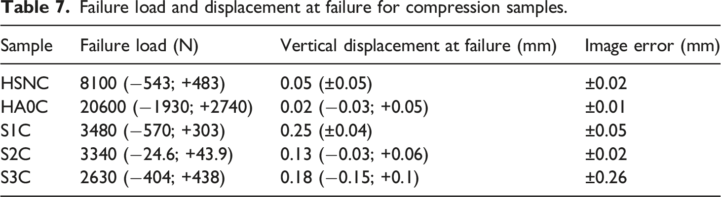
Experimental results are reported in Tables 7 and 8. While the failure load variation is relatively small among samples of the same type (at most 13.27% for honeycombs and 16.61% for corrugations), the vertical displacement variation is significant and this has an effect on evaluating sample stiffness. However, the relative performance between the baseline honeycomb and the printed honeycomb can still be obtained reliably based on a few factors. Firstly, an 80 mm × 80 mm printed honeycomb sample could not be crushed in compression by the 50 kN Instron machine, while the standard honeycomb fails at around 8 kN on average. Consequently, the printed sample size was reduced to 50 mm × 50 mm and in this case HA0C is shown to carry four times the load per unit mass compared to HSNC before failing, as seen in Table 8. Moreover, the sample specific stiffness difference between the two honeycomb samples types is around one order of magnitude in favour of the printed honeycomb core. The large difference in wall thickness makes HA0C perform better in compression that the baseline core. Force displacement curves for HSNC samples. Image displacement on the left and Instron displacement on the right. Force displacement curves for the three corrugation types: S1C (left), S2C (middle), S3C (right). Imaging data only. Failure load and displacement at failure for compression samples. Specific strength and specific stiffness for compression samples.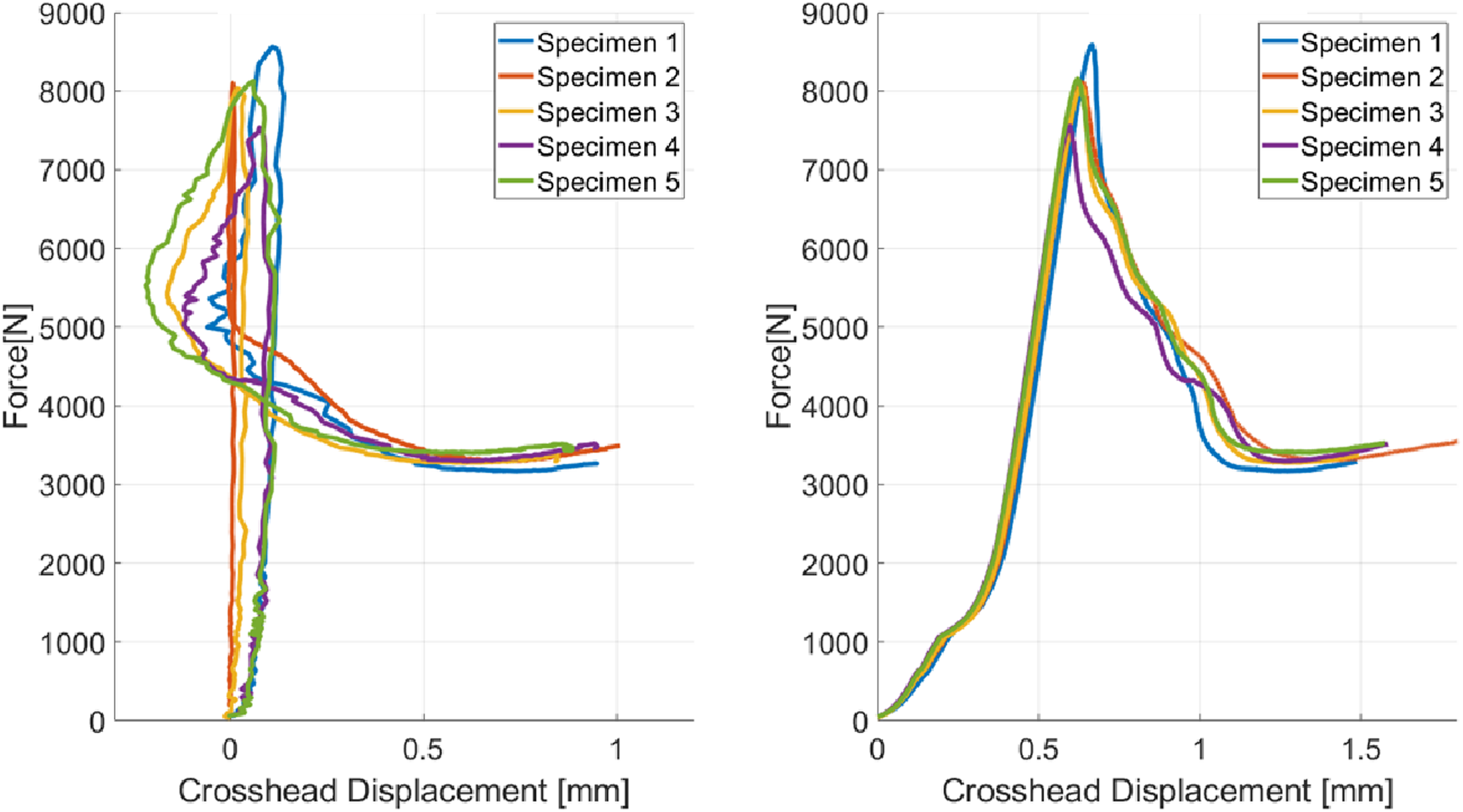
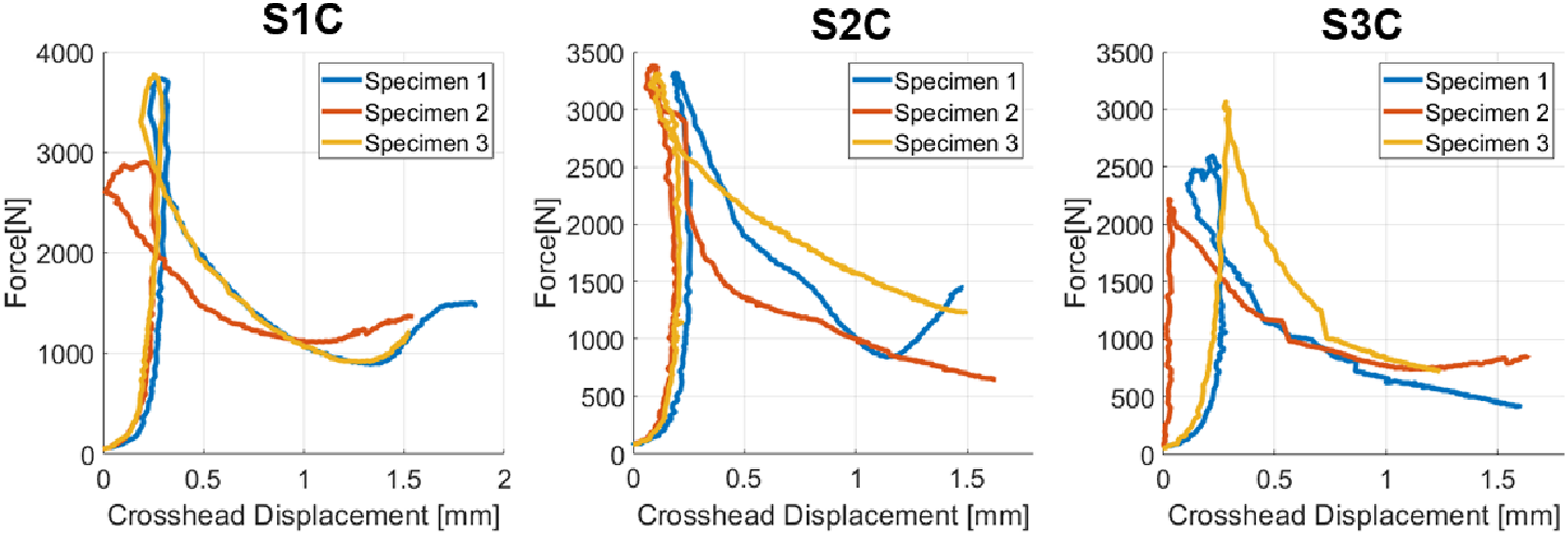
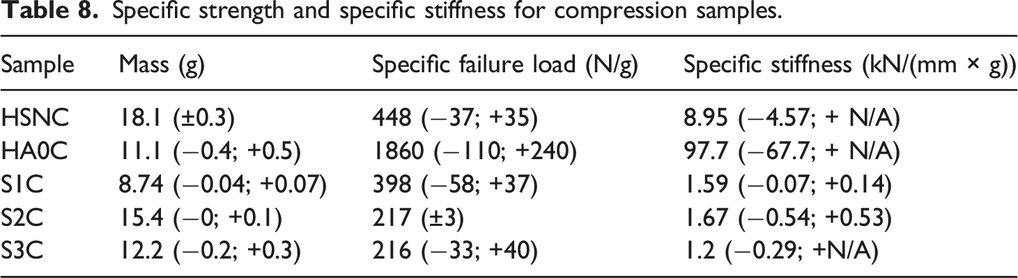
Among the corrugated samples, S1C has the highest specific failure load due to having half the sample height compared to the other corrugation types. This sample is close to matching the standard honeycomb in terms of load carried per unit mass showing the efficiency of the corrugated geometry under compression. The specific stiffness is similar between the three corrugated geometries. In compression, the 3D printed honeycomb demonstrates that it can outperform the baseline honeycombs currently in use, while the relative performance of the corrugated geometry is dictated by the height of the sample.
Conclusion
The paper provides valuable insight into the fundamental structural performance of AM sandwich panel cores with the goal to improve on the current baseline core design through 3D printing. It was determined that in bending the printed honeycomb samples all fail through top facesheet buckling, while the baseline panels fail through core buckling. In the case of the printed samples, the core is over-designed for the facesheets and the samples fail sequentially as cracks propagate and release energy producing several step jumps in the force-displacement curve.
When compared against the baseline CFRP-AL panels, the 3D printed honeycomb cores carry up to twice as much load per unit mass in bending and four times as much in compression, while also being stiffer. In addition, simply increasing the core contact area with the facesheets in the printed bending samples further increases their performance. As a result, printing sandwich panel cores can lead to improvements in the structural performance as a result of the geometric freedom of the manufacturing method. The limitation of the printed samples lies in the fact that they are heavier compared with the current baseline, and although they can perform better per unit mass, the minimum print thickness must be reduced to enable their integration in satellite cores.
The paper also assesses the structural performance of corrugated panels with a view to include this geometry in future hybrid core designs for improved impact shielding. These fully printed panels carry less load per unit mass and are less stiff than the honeycomb samples, but together with the honeycomb geometry they may present a promising avenue for developing hybrid multifunctional cores.
Footnotes
Declaration of conflicting interests
The author(s) declared no potential conflicts of interest with respect to the research, authorship, and/or publication of this article.
Funding
The author(s) disclosed receipt of the following financial support for the research, authorship, and/or publication of this article: The structural testing work reported was funded through the European Commission Horizon 2020, Framework Programme for Research and Innovation (2014-2020), under the ReDSHIFT project (grant agreement n. 687500).