
Abstract
In recent years, glass fiber-reinforced polymer (GFRP) composite materials have become a viable alternative material for different engineering applications due to their superior/excellent properties. The strength of the composite is positively related to the orientation of the fiber material. However, the machinability is still a problem when components are manufactured using the GFRP composites due to their anisotropic properties. The aim of this analytical research paper is to investigate the influence of fiber orientation on the strength and machinability in slot milling of GFRP fabricated using the vacuum infusion method. The fiber orientations of 0°/90° and ±45° are used for the fabrication of GFRP composite laminates. The experiments were conducted using an orthogonal array. Analysis of variance was employed to determine the influence of milling parameters such as cutting speed, transverse feed rate, and axial depth of cut (A.D.O.C.) for the surface finish (Ra), cutting force, and Machinability index (MI). The MI is calculated based on specific cutting pressure. The influence of fiber orientation on the cutting force and surface topography was analyzed. It was concluded that the cutting forces were significantly influenced by the fiber orientation and not affected by the machining parameters. The results revealed that the transverse feed rate was the primary influencing parameter responsible for the increase in MI (40 to 56%). The A.D.O.C. was accountable for the increase in cutting force (55 to 94%). Similarly, the cutting speed influenced Ra, which increased from 17 to 37%.
Introduction
Fiber-reinforced polymer (F.R.P.) composite materials are considered to be an excellent economical alternative to other engineering materials. They are used extensively in highly corrosive environment applications such as automobile, aerospace, sea-vehicles, robots, and wind turbines (nacelles). Among the F.R.P. composites, the Glass fiber-reinforced polymer (GFRP) possesses enhanced specific strength and specific stiffness. They also have good corrosive resistance, lower thermal expansion, comparative creep/yield strengths, high specific weight ratios, etc. 1 The increase in GFRP applications demands an increase in the requirement for different machining processes. This is needed to facilitate various features by cutting off the materials using drilling, milling, turning, etc. Among the various machining processes, milling is the most preferred process for making grooves, slots, keyways, etc. in GFRP laminates.2-4
Achieving an excellent outside surface finish with conventional methods of machining is very difficult due to the anisotropic and non-homogeneous nature of composites. The practical experience and theoretical knowledge available for the machining of conventional materials cannot be directly applied to this newly developed polymer-composite material. This is due to extensive variation in fiber strength, fiber orientation, and the resultant properties of matrix materials. Few drawbacks were encountered during the drilling process of the GFRP composites. They included delamination, fiber-detachment, localized burning, fizzing, and low surface roughness (Ra) of the machined component. 5 The fiber thickness, orientation, type of bonding, and machining parameters play an essential role in delamination failures. In the drilling process, different types of delamination failures occur, including strip-out and push-out. Mostly, these failures happen because of the interplay layer failure and machining parameters like extensive feed rate, depth of cut, and cutting speed.6,7 Even in the drilling operation, the tool size affects the cutting forces, which influence the laminated composite structures. In order to overcome this, the cutting edge radius is varied to induce the chip removal rate and specific cutting forces. Moreover, a simplified geometry is developed to estimate the runout that influences the micro-milling machining process.8,9 Among the various composite machining processes, milling is an essential process for cutting high-quality slots and keyways. Milling of composites is materially different from the machining of homogeneous metal materials due to the adapted cutting mechanism.
When the milling process is performed on the GFRP laminates, many undesirable stress problems come into existence. The mechanism of material removal is completely varied at different fiber orientations in the GFRP milling process. This may be the reason for various cutting forces in the GFRP machining process. This also causes low production quality in the laminate layer, which leads to manufactured defects. Recent research studies have focused on finding the exact relationship between the process operating parameters and the achieved machining quality. The relationship is expected to increase the milling efficiency of composite with reduced product damages.10-12 Several researchers have investigated different laminates with different fiber orientations and their workability under various machining conditions during the milling process. The investigations done on the cutting tool and material revealed the influence of fiber orientation on the surface roughness. The researchers concluded that the optimal cutting parameter combinations would give enhanced surface finish.13-15 Time optimization techniques and numeric simulations like Taguchi, ANOVA, and the Genetic algorithm method are used for minimizing the material and energy wastage. They are also used for optimizing the machining process by reducing the machining time and simultaneously ensuring the surface quality of the machined workpiece. Researchers have determined the optimized machining process parameters such as cutting speed, feed rate, point angle, and chisel edge width in the drilling operation of different composite laminates like CFRP and GFRP using these methods.16,17 From these techniques and simulations, it was found that the feed rate is the most significant parameter influencing the cutting force (thrust force) and the resultant surface finish. Machinability index (MI) is an essential factor that is used to define the material property of newly developed materials. MI defines the ability of the material in the fabrication of the component using the material removal process. If the MI is more, the material is easy to machine. If the MI is less, the material is hard to machine. In such cases, evaluating the machinability of the composite material is difficult, as it mainly depends on the original Ra and cutting pressure. Considering these factors, a new machinability index method was developed for different composites.18-23 The selected combination of two polymer composites, layup sequence, and the method of fabrication also influenced the machining parameters.
From the literature, it is evident that most of the researchers have not given a clear report on the influence of combined fiber orientations in machining by analyzing the cutting force, Ra, and machinability index (MI). The present research work outlined in this paper explains the influence of fiber orientation on the end milling of 0°/90° and ±45°on the GFRP composites manufactured using the vacuum infusion method.
Specimen fabrication and mechanical properties evaluation
The GFRP laminates having dimensions of 100 mm × 100 mm cross-sectional area were fabricated using the Vacuum infusion method. Among the various methods of fabrication, this method was selected because it produced higher fiber volume fractions, lower void contents, and higher strength when compared to the hand lay-up method. For the fabrication of GFRP laminates, the resin of Araldite LY556 epoxy was used with a curing hardener of HY 951 grade. To make the laminate thickness of 10 mm, each layer of the E-glass woven fabric was kept at 0.3 mm thickness. Also, 60% of fiber volume fraction was used. The 50 plies of fiber were stacked in sequence with the orientation of 0°/90° and ±45° and placed alternatively. In the Vacuum infusion method, the mould required for the first stage was placed on the table, and a thin layer of resin was applied on the lower surface of the mould. The pre-impregnated glass fiber was placed on the mould to ensure that the fiber orientation met the required orientation. The vacuum pump was used to squeeze the excess resin. Then, the resin was applied over the first layer, and the second layer was placed on the first layer. This procedure was repeated until the required thickness of 10 mm was obtained. After the vacuum infusion, it was cured at a pressure of 1 bar for 2 hours. The same procedure was repeated for fiber orientations of 0°/90° and ±45°.
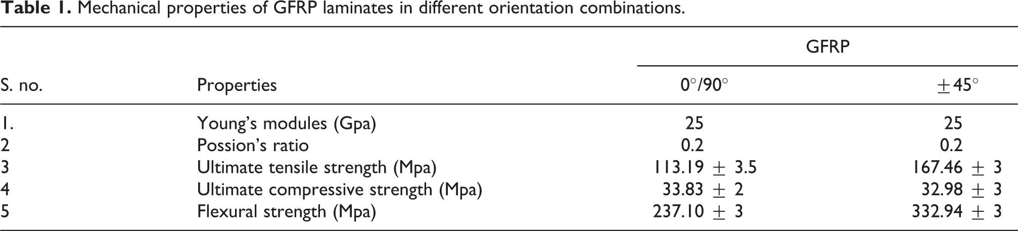
For the evaluation of mechanical properties by tensile, compressive, and flexural tests, samples were cut as per the ASTM D3039, ASTM 695, and ASTM 790 standards test methods using the water jet cutting machine. The mechanical properties were studied using the universal testing machine model TUC-CN 200 as per the ASTM standard. The mechanical properties are shown in Table 1.
Mechanical properties of GFRP laminates in different orientation combinations.
Experimental work
Methodology
The experiments were carried out on different orientations of GFRP laminates of thickness 10 mm with four fluted H.S.S. end mill with a 10 mm diameter. The tool was selected as per the literature survey.
For slot machining, a C.N.C. vertical machining center model “LV45” having specifications of 15kva power, table size 600 × 350 mm, and cutting speed in the range of 80 – 8000 rpm was used, as shown in Figure 1(b). For the measurement of machining forces in three directions (along with the feed (Fx), thrust (Fy), and axial (Fz)), a milling tool dynamometer was used. The dynamometer used three digital indicators with a maximum range of 50 kgf, which is shown in Figure 1(c).
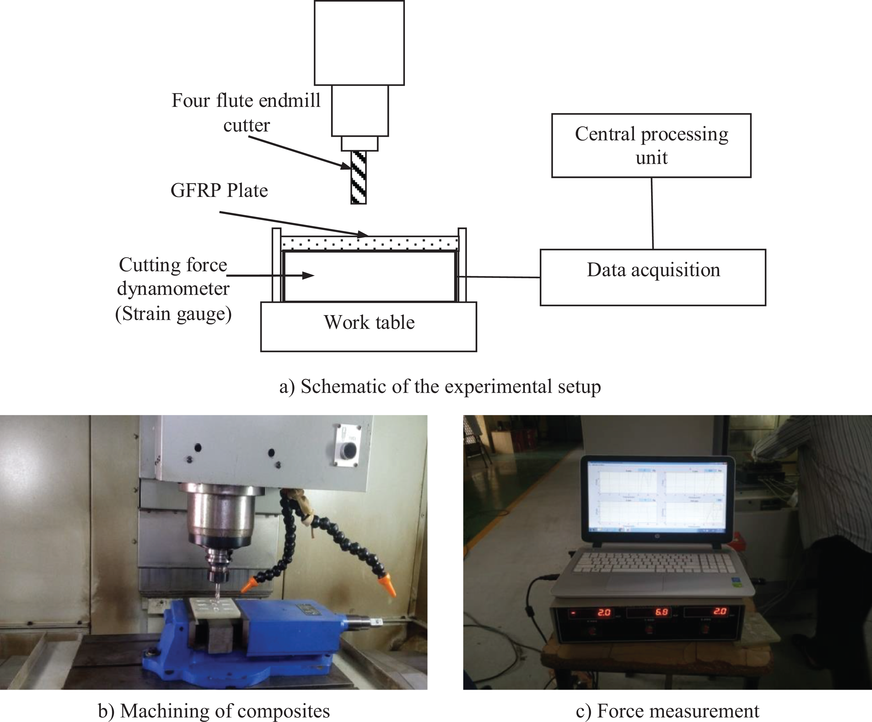
Experimental setup.
The machining arrangement of the fabricated GFRP laminate with cutting force measurement and its schematic diagrams are shown in Figure 1(a). The slot milling of 20 mm length was machined on each GFRP laminate. The cutting forces were recorded and analyzed for each slot by considering different parameters such as transverse feed rate, cutting speed, and axial depth of cut (A.D.O.C.). The milled GFRP laminates of 0°/90° and ±45° fiber orientation are shown in Figure 2.
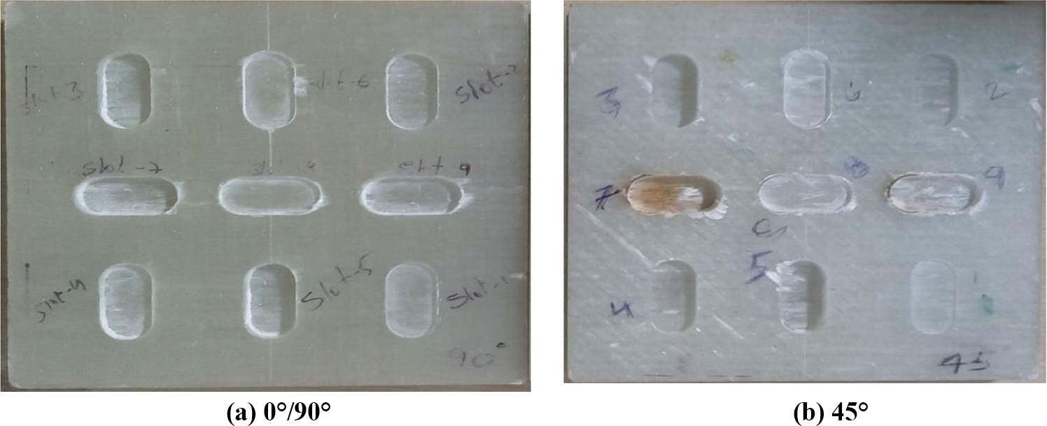
Specimens after machining GFRP 3 (a) 0°/90° and 3 (b) ±45° laminates.

Orthogonal cutting forces of three directions.
Selection of machining parameters and levels
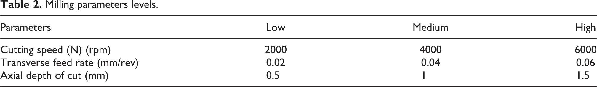
The machining parameters such as cutting speed, transverse feed rate, and the A.D.O.C. levels (low, medium, and high) are given in Table 2. The sample orthogonal cutting forces of three directions are shown in Figure 3. The three levels were selected based on the design of experiments L9 Orthogonal Array. The responses of output parameters, i.e. surface roughness (Ra), cutting force, and the machinability index (MI), were analyzed using ANOVA. The parameters were selected based on a comprehensive study of the C.N.C. vertical milling of metallic materials by considering the computation of the orthogonal cutting forces. By analyzing these parameters, the optimum parameters of cutting forces with good Ra and MI of the GFRP workpiece were obtained. The surface roughness (Ra) was measured on the machined surface of the workpiece at three different locations (beginning, middle, and end of the cut) along the length of the slot in the feed direction. The measurement was done using a non-contact surface roughness measurement equipment (Model: CCI Lite, Make: Taylor Hobson, UK) with 0.96 mm cut of length and 333 mm traverse length.
Milling parameters levels.
Results and discussion
In this investigation, the machinability of two types of GFRP composite fiber orientation laminates (manufactured using the Vacuum infusion method) was evaluated using the end milling process, which involved a four flute H.S.S. end mill tool. The slot length of 20 mm was selected for machining. The machinability was evaluated by analyzing the cutting force in the workpiece (F). The resultant cutting force value was determined using Equation 1. The cutting pressure and MI for this material were calculated from the resultant cutting force using Equations 2 and 3.5,10


where Ks is the specific cutting pressure (N/mm2), F is the cutting force (N), f the transverse feed rate (mm/rev), d the A.D.O.C. (mm), Ra (mm), α and β the parameter weight constants. The values of α and β were obtained to provide a similar contribution for Ks and Ra in MI. The relation between the average Ks and the average Ra helped in calculating α = 130 and β = 1, to obtain the results of this investigation. 5
The results of the targeted experimental responses to the cutting force were fed into the Minitab 17, and Taguchi analysis was done to find the effect of the parameters on the cutting force. The average value of each measurement was taken for subsequent analysis. The results for the cutting force, Ra, cutting pressure, and MI of different laminates are shown in Table 3.
Experimental results.

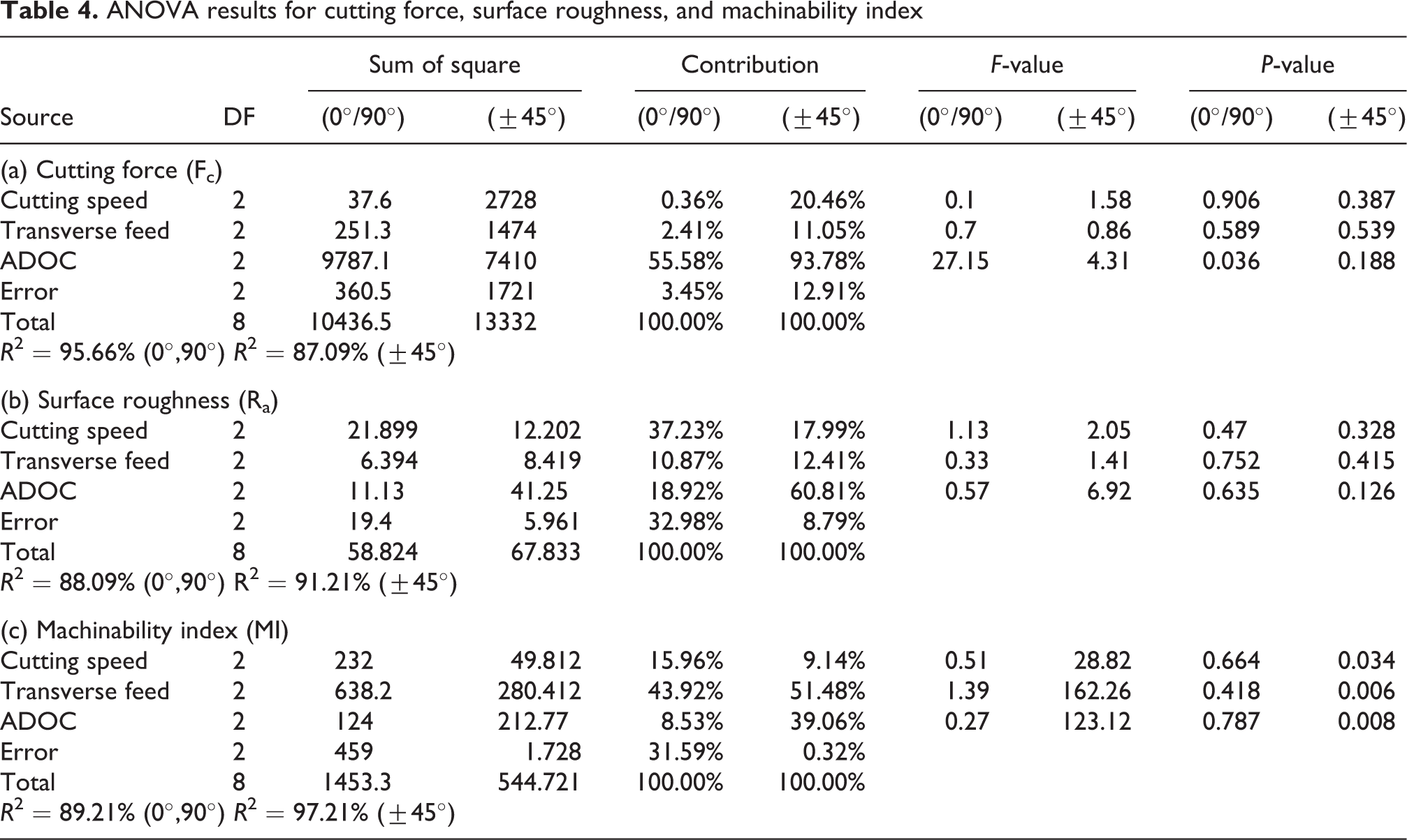
ANOVA analysis was carried out for a 5% level of significance (confidence level significance is 95%). The ANOVA results with cutting force (Fc) during the milling of GFRP laminates are shown in Table 4(a).
From the analysis, it was found that the A.D.O.C. and feed had significant contributions both physically and statistically on the cutting force obtained. The effect of the parameter cutting speed was found to be insignificant. It was also evident that the A.D.O.C. had more influence on the resultant cutting force for the fiber orientation of ±45° fiber orientation (93.78%) than the 0°/90° (55.58%).
Table 4(b) shows the ANOVA results with Ra. From Table 4(b), it was observed that the A.D.O.C. had more influence on the Ra in both fiber orientations. It was also evident that Ra was more influenced by the cutting speed of around 37.23% of contribution than the A.D.O.C. for the fiber orientation of 0°/90°. However, in the case of ±45° fiber orientation, the A.D.O.C. had more influence (60.81%) than the cutting speed (17.99%).
Table 4(c) shows the assessment of MI as a function of the cutting speed, transverse feed rate, and A.D.O.C. for different combinations of fiber orientations. It was evident that the MI was influenced more by the feed rate when compared with the A.D.O.C. and cutting speed. This was attributed to an increase in feed rate, which increased the length of contact between the tool and the workpiece. This eventually increased the MI. It was also theoretically proved from Equation 3, 5 where MI was influenced purely by machining parameters such as transverse feed rate and axial depth of cut irrespective of the fiber orientation or properties of the workpiece material. But, for the fiber orientation of ±45°, the A.D.O.C. was found to be more influenced by Ra (51.48%). Also, the cutting speed was an influencing factor for the fiber orientation of 0°/90° (43.92%).
Figure 4 shows the response graph Ra as a function of machining parameters. When the parameters were increased, the Ra also increased irrespective of the fiber orientation. However, a decreasing trend was observed when the cutting speed and transverse feed were increased. The A.D.O.C. and cutting speed were the most influencing parameters. However, A.D.O.C. influenced the maximum amount of Ra. This was observed in the case of ±45° fiber orientation due to the increased fiber pull-out in the machined direction. Cutting speed also influenced the highest amount of Ra, which was observed in the case of 0°/90°. The S.E.M. and 3D surface topography analysis of machined surface revealed a higher Rat a moderate cutting speed of 4000 rpm, a moderate transverse feed rate of 0.04 mm/sec, and a high A.D.O.C. of 1.5 mm (Figure 5).
ANOVA results for cutting force, surface roughness, and machinability index

Response graph for surface roughness with machining parameters.
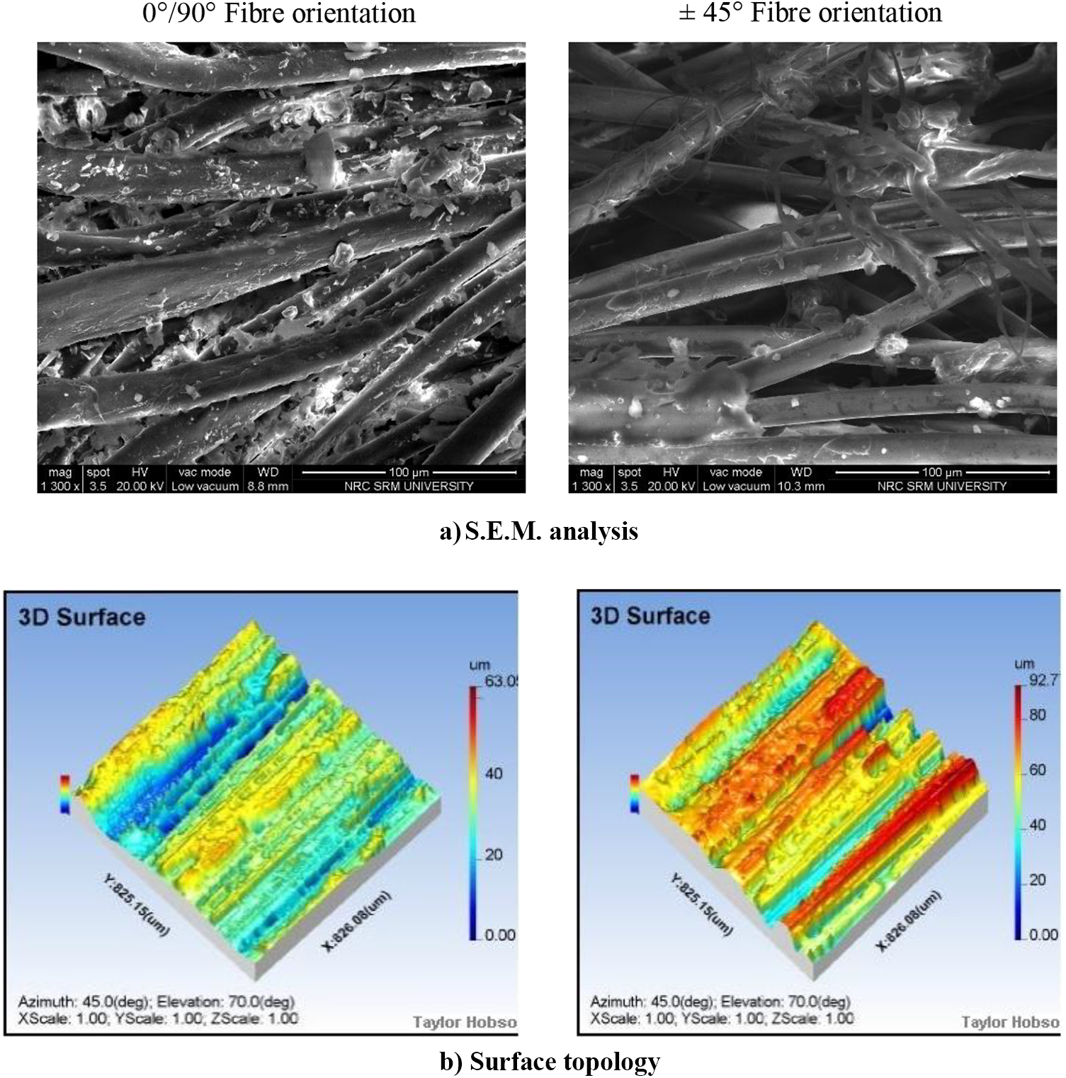
Surface roughness analysis on the machined surface.
Figure 6 shows the assessment of the resultant cutting force as a function of cutting speed, transverse feed rate, and A.D.O.C. It was evident that the A.D.O.C. was the most influencing parameter responsible for the increase in the mean cutting force. For 0°/90° fiber orientation, a small variation was observed under increased cutting speed and transverse feed rate. A large deviation was seen in the case of ±45° orientation. This was due to the large number of contact points along and against the direction of fiber orientation in ±45°. But for 0°/90° orientation, there were only parallel and vertical contact points.
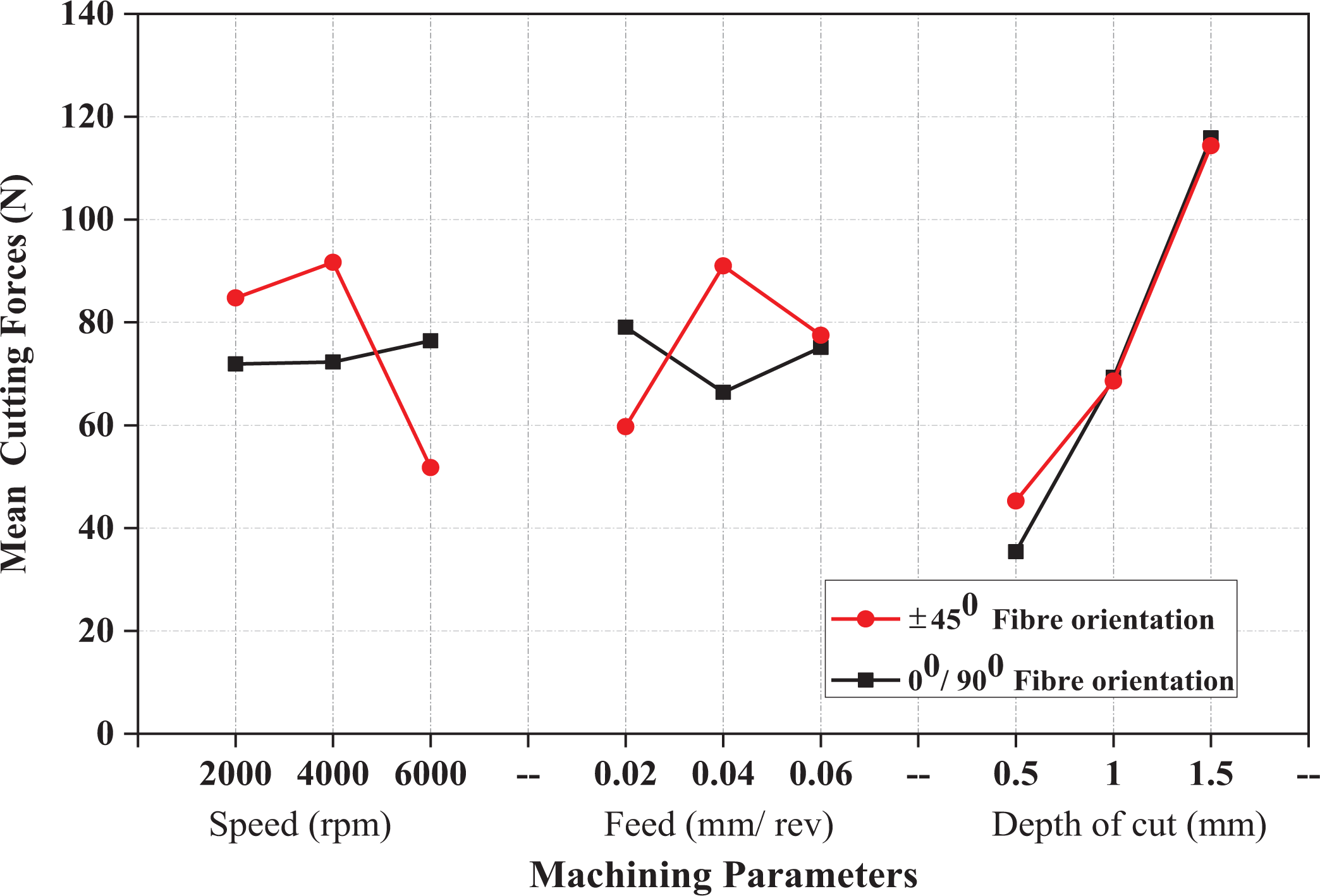
Response graph for cutting forces with machining parameters.
Figure 6 indicates that the tool (or) transverse table feed at an orthogonal angle cutting configuration to the fiber orientation resulted in lower cutting force during milling. Even though the end mill was fed orthogonal to the fiber orientation, the actual material removal (chip formation) happened only after the engagement of the cutting flute into the workpiece. It was noticeable that the highest chip loading occurred at the center of the cutting. Figure 7 depicts the results of the magnitude of the cutting forces observed earlier. For 0°/90° fiber orientations, bending, and buckling failures of the fibers was observed 24 as the cutting flutes slide along the fiber shown in Figure 7(a). This was the reason for the lower magnitude of cutting forces. In the case of ±45° orientations, the GFRP tool feed direction was along the fiber orientation in milling, as shown in Figure 7(b). In the case of crushing-dominated fiber, the failure was more pronounced. This may be the reason for the higher magnitude of cutting force. 25 However, during milling, the direct contact of the flank face of the cutting tool on the fiber resulted in the higher friction and wear of the end mill. Due to this, the cutting forces increased considerably. 26
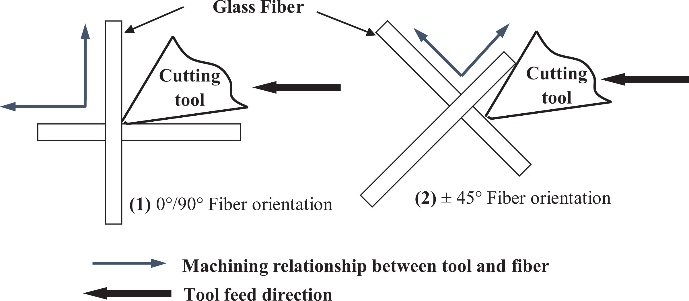
Machining relationship in GFRP milling (a) parallel and vertical relation and (b) along and against the fiber direction.
In 0°/90° orientation, the fibers were fractured, and pull-outs were visible, as revealed from Figures 6 and 8. In ±45° orientation, the fibers were purely fractured and devoid of pull-outs, in spite of the high cutting force. The MI graph shown in Figure 9 reveals the proportionate increase of the feed rate with the MI. Figure 10 shows the percentage contribution of milling parameters, which influenced the output variables like cutting force, Ra, and MI. From Figure 10, it was evident that the feed rate was the most influencing parameter responsible for the increase of MI (40 to 56%). The A.D.O.C. was the most influencing factor responsible for the increase of cutting force (55 to 94%). For Ra, the cutting speed was influenced around 17 to 37%.

Schematic diagrams of different fiber orientations.

Response graph for machinability index with machining parameters.

Percentage contribution of machining parameters on output variables.
Conclusions
This research paper presents the surface roughness (Ra), cutting forces, and machinability index (MI) for different combinations of fiber orientations in the finished GFRP. The obtained results are summarized as follows. The fiber orientation of ±45° exhibited an enhanced ultimate tensile strength and flexural strength when compared with the 0°/90° combination. The Ra measurement, influenced by the cutting speed in 0°/90° fiber orientations and axial depth of cut in ±45° fiber orientations, was 37% and 61%, respectively. The influence of transverse feed rate was found to be inconsequential. The overall effect on Ra in different fiber orientations may be due to the divergent mechanisms of material removal (chip formation) at various machining conditions. An essential factor to consider is that the Ra value alone is not sufficient to establish the surface properties of the machined surface of F.R.P. composites due to fiber protrusion. It must be used along with S.E.M. images for verification to determine the status of surface integrity and morphology of the machined laminates. The resultant cutting force was significantly affected by the A.D.O.C. and feed rate. The A.D.O.C. had a higher contribution of around 56% and 93% for 0°/90° and ±45° fiber orientations, respectively. This was because the A.D.O.C. and feed rate controlled the dimensions of the undeformed chip. The cutting speed was observed to have only a marginal effect on the cutting force. The results precisely established that the feed rate was the most influencing parameter responsible for the increase of MI for both the fiber orientation combinations.
Footnotes
Declaration of conflicting interests
The author(s) declared no potential conflicts of interest with respect to the research, authorship, and/or publication of this article.
Funding
The author(s) received no financial support for the research, authorship, and/or publication of this article.