
Abstract
Magnesium oxide-reinforced wood fiber composites (MgO/WF) are a new type of multifunctional material, which can be used in different occasions, such as shopping malls, hotels, and residential buildings. Referring to the relevant literature, there is no research on the milling performance of MgO/WF. In order to better understand the relevant knowledge of the processability of MgO/WF, three cutters with different helix angles were used in this experiment to carry out the cutting of MgO/WF, and the variation trend of its cutting force, tool wear, and surface roughness was measured. The results are as follows: First, under the same cutting parameters, the resultant force decreases with the increase of helix angle. Second, with the increase of helix angle, the tool wear was slightly improved. Third, the surface roughness (Ra) showed an increasing trend with the decrease of helix angle. In the end, when milling MgO/WF, better machined surface quality and less tool wear can be obtained by selecting the tool with larger helix angle.
Introduction
With the progress of science and technology, various new materials have been prepared, 1 –3 of which magnesium oxide-reinforced wood fiber composites (MgO/WF) are a recent new type of decorative material. It has a wide range of applications due to its high temperature resistance, flame retardant, and good mechanical properties. 4,5
MgO/WF use magnesium oxide, wood chips, and silicon dioxide as the main materials, its hardness is relatively high. With the addition of MgO, the mechanical properties were improved. However, it leads to increased tool wear and lower cutting quality. 6 The general tools cannot meet the processing quality requirements of MgO/WF. In order to meet the processing requirements of MgO/WF, the best choice is diamond cutter. 7 Diamond tools have extremely high hardness, high elastic modulus, low coefficient of friction, high thermal conductivity, and so on, 8 –10 so diamond tools can be qualified for processing MgO/WF.
According to the relevant literature, cutting force, 11 tool wear, 12 and surface roughness 13 are one of the research focuses of cutting, and they are directly related to the quality of products. 14 Cutting forces and surface roughness can be affected by chip thickness, tool angle, and cutting speed. 15,16 Chen et al. 17 used polycrystalline cubic boron nitride (PCBN) tools to turn the new alloy AD 730™ and found that the cutting speed and feed speed had a great impact on the cutting force. On the one hand, as the cutting speed increases, the cutting force gradually decreases, and on the other hand, the increase of the feed speed always led to a higher cutting force. Zhu et al. 18 investigated the relationship between cutting force and helix angle, cutting speed, and depth of cut when milling Luxury Vinyl Tiles. The results show that as the helix angle and cutting speed decrease, the cutting force increases, but as the depth of cut decreases, the cutting force also decreases. The cutting force of glass magnesium board under the milling of diamond tools with different taper angles was explored by Cao et al. 19 The research implied that the cutting force was positively related to the taper angle of the tool. The effect of machining parameters on the surface roughness of medium density fibreboard (MDF) was studied by Sutcu and Karagoz. 20 They found that the surface roughness decreases with the increase of the spindle speed, but increases with the increase of the feed speed and depth of cut. Additionally, Bayraktar and Turgut found the maximum cutting speed, minimum feed rate, and drill point angle reduced delamination to the greatest extent when machining carbon fiber-reinforced carbon matrix composites/Al 6013-T651 stacks. 21 In addition, Davim et al. 22 also found that the spindle speed has an important effect on the surface roughness in the test of milling MDF.
In order to achieve the final required size and surface roughness of products, the MgO/WF need to undergo secondary processing. Drilling, sawing, and milling are widely used in secondary processing, in which milling is used most. 23 Because milling is the rotation movement of cutter teeth, allowing higher cutting speed can greatly improve the production efficiency. Meanwhile, milling is also a research focus in the field of material processing. 24 Compared with a straight-tooth cylindrical milling cutter, using a helical-tooth milling cutter 18,25,26 to mill the workpiece is not only stable, less vibration, but also improves the processing quality and reduces noise.
Although helical milling has been applied in various material fields, 27 there is no research report on the cutting performance of helical milling MgO/WF. At the same time, MgO/WF as a new type of engineering material, how to scientifically choose the tool geometry is an urgent problem to be solved.
In this article, the cutting performance of milling MgO/WF with diamond helical cutter was studied. The purpose of this study is to investigate the changes in cutting force and surface roughness in terms of helix angle, analyze tool wear, and surface morphology after cutting. The results discussed in this article could add some knowledge of the machinability of helical milling MgO/WF.
Materials and methods
Testing material
MgO/WF were adopted as the machining object. The mechanical properties of the workpiece were tested before the experiment, and the properties of the materials were listed in Table 1. The composition of the material was analyzed by X-ray fluorescence spectrometer (ARL9800XP+, Thermo Fisher Scientific, China). It was found that the main oxide components were MgO, Cl, SiO2, and CaO. The content of MgO is the most, accounting for 38.32%. Figure 1 is a material image taken under a digital microscope (ZW-H1600, Zhongwei Co., Ltd, Shenzhen, China). MgO/WF were milled by helical diamond cutting tools. The main chemical components of the helical polycrystalline cemented diamond (PCD) cutters are carbon, cobalt, and tungsten carbide, and it was made of diamond powder sintered by metal binder. Its geometries and properties were listed in Table 2. The tool geometric parameters were determined by literature research and factory investigation of the factory for processing MgO/WF.
Mechanical properties of MgO-reinforced wood fiber composites.

MgO/WF: magnesium oxide-reinforced wood fiber composites.
Mechanical properties and geometry of PCD tools.

PCD: polycrystalline cemented diamond.
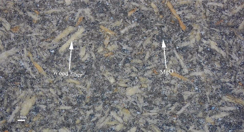
Micrograph of workpiece.
Experimental methods
In this experiment, helical milling was used for the experimental study.
As shown in Figure 2(a), the PCD cutter was clamped in a commercial computerized numerical control (CNC) machining center (MGK01, Nanxing Machinery Co., Ltd, Guangzhou, China), and the MgO/WF were carried out on the CNC machining center by means of up milling. MgO/WF were placed on a dynamometer (Kistler 9257B, Switzerland) that collected date on cutting force. The dynamometer was then connected to a charge amplifier, through which date was transmitted to a computer and analyzed by DynoWare software (Version 3.2.0.0, Kistler Group). The data sampling frequency was set at 7100 Hz. As shown in Figure 3, during helical milling, three cutting forces were generated, named Fx, Fy, and Fz, and their resultant forces were defined as Fr, the expression of Fr was shown in equation (1):

where Fx is parallel to the feeding direction, Fy is perpendicular to the feeding direction, and Fz is parallel to the cutter axis.

Experimental setup.

Diagram of cutting forces.
As displayed in Figure 2 (b), the surface roughness of the specimen after helical milling was measured by a surface profiler (S-NEX001SD-12, Tokyo Seimitsu Co., Ltd., Tokyo, Japan) and the results were calculated by ACCTee software (ACCRETECH, Tokyo Seimitsu Co., Ltd., Japan). Ra is used as the index to evaluate the surface roughness. 28 The cutoff and sampling length were determined as 0.8 and 10 mm.
The selection range of cutting force from DynoWare software (Version 3.2.0.0, Kistler Group) is shown in Figure 4, and the cutting force between t1 and t2 is in a stable state. Select a small section from this interval, select 10 reasonable maximum points after filtering by Matlab2016 (Version 9.1.0.441655), take the average value, and then calculate the resultant force by equation (1). There are five groups in total, and the average value is taken as the resultant force under the cutting condition. The surface roughness is measured at the position of approximately 1, 6, and 11 mm in the direction of the length of the processed surface of 13 mm. The average of the three measured values is taken as the surface roughness.
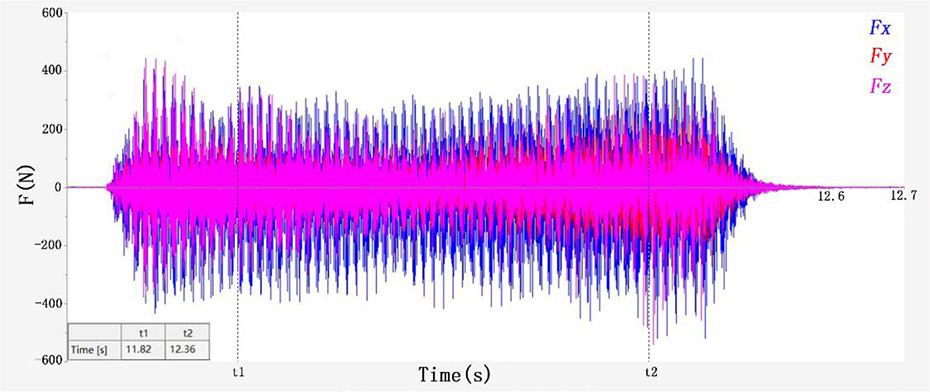
Selection of cutting force.
Results and discussion
Experimental scheme and results
The test mainly studies the effect of the change of tool helical angle on cutting force and surface roughness (Ra) under the condition of the same cutting speed and depth of cut. The experimental design scheme and results are shown in Table 3 below. The feed rate (vf) of this study is 67 mm/s.
Results of resultant force and surface roughness (Ra).

Analysis of cutting force
The influence of cutting parameters on cutting results is important.
29
The resultant cutting force of different helical angle tools at the same cutting parameters is shown in Figure 5. It can be seen from the figure that with the increase of the helical angle, the cutting force of the three kinds of cutting speeds decreased. The maximum cutting force appeared at the cutting speed v = 35 m/s. This is because feed per tooth (equation (2)) increased with the decreased of spindle speed (cutting speed is positively associated with spindle speed), and the feed per tooth increased, which led to more chips need to be removed. Therefore, when the cutting speed decreased, the feed per tooth increased, which enhanced the cutting force. At the cutting speed v = 35 m/s, the resultant force of the tool with 70° helix angles decreased by 14.8% and 8.7%, compared with the tool with 54° and 62° helix angles. At the cutting speed v = 40 m/s, the resultant force of the tool with 70° helix angles decreased by 20.8% and 11.5%, compared with the tool with 54° and 62° helix angles. At the cutting speed v = 45 m/s, the resultant force of the tool with 70° helix angles decreased by 20.3% and 8.2%, compared with the tool with 54° and 62° helix angles. Specifically, at higher cutting speeds (v = 40 and 45 m/s), the increase of helix angle has more significant effect on reducing cutting force. In general, the resultant cutting force decreases with the increase of helical angle. The changing trend of cutting force is similar to the results of milling Luxury Vinyl Tiles with helical cutter by Zhu et al.
18
Effect of helix angle and cutting speed on cutting force.

where vf is the feed rate, fz is the feed per tooth, n is the spindle speed (The test spindle speed is 4777, 5460, and 6142 r min−1), and Zn is the number of teeth (there were six teeth in this work).
In helical milling, the chip width of helical PCD cutter varies with the position of the tooth. Helical teeth are gradually cut into and out of the workpiece during cutting. Theoretically, at the beginning of cutting, each tooth is just a point on the cutting edge that is in contact with the MgO/WF, chip width is very small. With the milling of the tool (the position of the tooth changes), the chip width increases gradually, after reaching a certain value, the chip width decreases gradually with the milling of the tool. See Figure 6 for details.
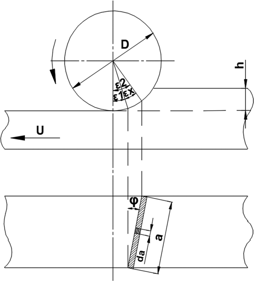
Helical milling process.
For a cutter tooth, the relationship between chip width and rotation angle and helix angle is expressed by equations (3) and (4).

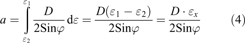
where a is the chip width,
Helical milling cutter can make the cutter teeth gradually cut into and out of the workpiece. As the helix angle increases, the process of cutting in and out becomes slower. At the same time, the increase of the helix angle also increases the number of simultaneous working teeth and makes the cutting process stable. During the milling process, the rake of the tool directly acts on the workpiece being cut, and the chips are discharged along the rake surface. The rake angle of the tool facilitates the deformation and discharge of chips, the larger the rake angle, the smaller the cutting resistance. 30,31 Increasing the helix angle makes the actual rake angle larger, the cutting edge becomes sharper, the cutting edge is easier to bit into the workpiece, and the chips will be more easily discharged from the cutting layer, so the cutting will be smoother and the cutting force will be smaller.
Analysis of tool wear
When cutting MgO/WF, the tool was squeezed and rubbed by MgO/WF and chips, resulting in tool wear. Tool wear will increase cutting resistance, lower cutting quality, and lower efficiency, which is a serious problem. 32 In order to study the effect of helix angle on tool wear mechanism in milling MgO / WF. After cutting tests, tool wear analyses were performed to measure some tool wear parameters. The flank wear parameter VB (the width of wear band on the flank) was used as the evaluation index. 33 In this experiment, macroscopic wear view of flank wear was obtained with digital microscope (ZW-H1600, Zhongwei Co., Ltd, Shenzhen, China). The morphology of flank wear was collected after milling length of 1000 m. Figure 7 shows the flank wear parameter VB of the tool with 54°, 62°, and 70° helix angles. It can be clearly seen that with the increase of helix angle, the VB value gradually decreases, which may be related to larger helix angle tools were subjected to less cutting force. Therefore, it can be considered that the tool with larger helix angle has better wear resistance.
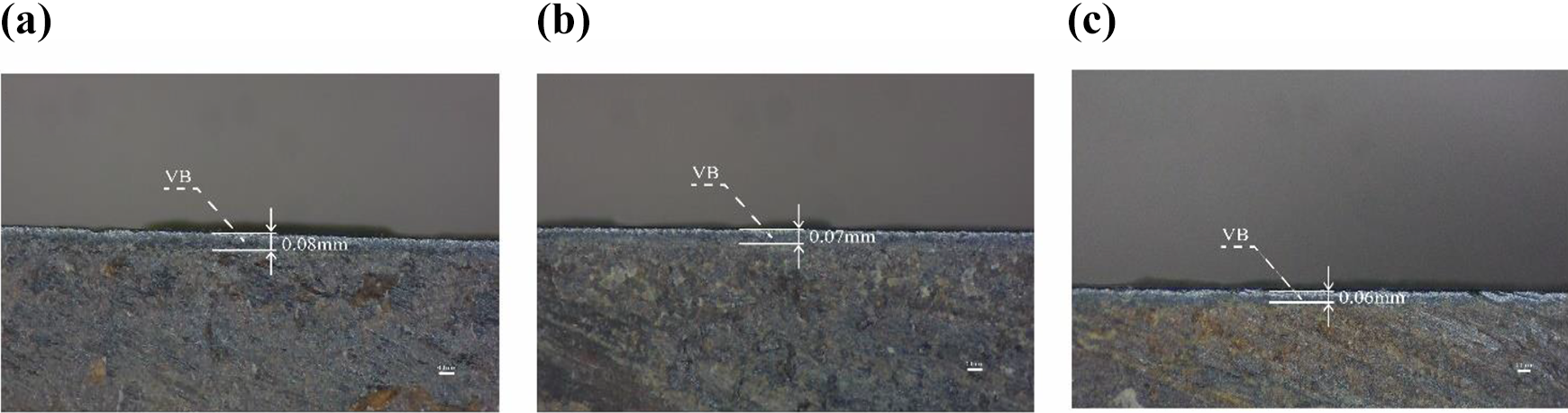
Morphology of flank wear for different helix angle cutters with the same milling length (cutting speed 45 m/s, feed rate 67 mm/s, and depth of cut 1.5 mm).
Analysis of surface roughness
Depending on the constant cutting speed and depth of cut, the surface roughness created during the milling of the MgO/WF with the three kinds of helical angle cutting tools is given in Figure 8.

Effect of helix angle and cutting speed on surface roughness.
As can be seen from the figure, the surface roughness of MgO/WF material gradually decreases with the increase of helix angle. At the cutting speed v = 35 m/s, the Ra of the tool with 70° helix angles decreased by 17.0% and 11.8%, compared with the tool with 54° and 62° helix angles. At the cutting speed v = 40 m/s, the Ra of the tool with 70° helix angles decreased by 20.9% and 8.7%, compared with the tool with 54° and 62° helix angles. At the cutting speed v = 45 m/s, the Ra of the tool with 70° helix angles decreased by 17.3% and 2.3%, compared with the tool with 54° and 62° helix angles. Tools with larger helical angle have better surface quality. When the helix angle is 70°, the roughness values of cutting speed 40 and 45 m/s came out to be very close to each other.
The damage morphology of the MgO/WF surface machined in different cutting conditions was shown in Figure 9. Burrs were observed on the machined surface for a 54° helix angle, 35 m/s cutting speed and 1.5 mm depth of cut, and for a 62° helix angle, 35 m/s cutting speed and 1.5 mm depth of cut. Ripples could be seen on the machined surface when the helix angle was 62°, cutting speed was 40 m/s, and the depth of cut was 1.5 mm. Pits were found on the machined surface when the helix angle was 62°, cutting speed was 45 m/s, and the depth of cut was 1.5 mm. Meanwhile, no obvious damage was found on the surface of MgO/WF machined with 70° helix angle tool. Under the same conditions, the main reason for this change is that the increase of the helix angle reduces the cutting resultant force, the cutting process becomes more stable, the vibration amplitude generated is smaller, and the cutting stability of the milling is improved. As a result, the surface roughness becomes better, that is, the Ra value gradually decreases. When the cutting speed increases, the surface quality of the workpiece becomes better. The expression between the cutting speed and the feed per tooth is shown in equation (4). When other conditions are the same, with the increase of speed, the feed per tooth decreases, the length of wavy stripe becomes smaller, and the material to be removed is less each time the cutter tooth cuts the workpiece, so the surface roughness becomes lower.
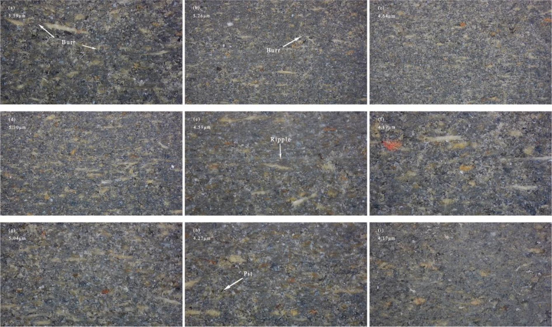
Surface pictures after cutting (the cutting conditions of (a) to (i) are consistent with the No. 1 to 9 in Table 3).
Conclusions
Based on single-factor experiments, the cutting force, tool wear, and surface roughness (Ra) were mainly studied from the tool geometry, when MgO/WF were milled by diamond helical milling cutters. The specific conclusions can be drawn as follows: Under the same cutting parameters, the resultant force decreases with the increase of helix angle. In particular, the degree to which the resultant force decreases with increasing helix angle at higher cutting speeds has a greater effect than at lower cutting speeds. With the increase of helix angle, the tool wear was slightly improved. The surface roughness (Ra) showed an increasing trend with the decrease of helix angle. When the helix angle is 70°, the roughness values of cutting speed 40 and 45 m/s came out to be very close to each other. When milling MgO/WF, better machined surface quality and less tool wear can be obtained by selecting the tool with larger helix angle.
Footnotes
Declaration of conflicting interests
The author(s) declared no potential conflicts of interest with respect to the research, authorship, and/or publication of this article.
Funding
The author(s) disclosed receipt of the following financial support for the research, authorship, and/or publication of this article: This research was funded by the National Natural Science Foundation of China, grant number 31971594.