
Abstract
In this study, the effect of adding nanosize additive to glass fiber reinforced composite plates on mechanical properties and surface milling was investigated. In the light of the investigations, with the addition of MWCNTs additive in the composite production, the strength of the material has been changed and the more durable composite materials have been obtained. Slots were opened with different cutting speed and feed rate parameters to the composite layers. Surface roughness of the composite layers and slot size were examined and also abrasions of cutting tools used in cutting process were determined. It was observed that the addition of nanoparticles to the laminated glass fiber composite materials played an effective role in the strength of the material and caused cutting tool wear.
Introduction
Composite material offer high strength and stiffness-to-weight ratio, low density, long fatigue life, high corrosion and wear resistances, which make them one of the most general-purpose materials used in many industries, such as aircraft applications, sporting goods, space equipments, marine, automotive, electrical and industrial systems, orthopedic parts, and constructions industry.1-10 Composite materials can be further strengthened by the contribution of carbon nanotubes (CNTs). 11 The superlative mechanical properties of multi-walled carbon nanotubes (MWCNTs) make them the filler material of choice for composite reinforcement.12,13 MWCNTs consist of an array of such cylinders formed concentrically and separated by 0.35 nm, similar to the basal plane separation in graphite. 14 Along with dispersion, aspect ratio, length on CNTs and alignment of CNTs into the matrix also changes the different properties of composites.15-19 The variation of many parameters, such as CNTs type, growth method, chemical pre-treatment as well as polymer type and processing strategy have given some results in fabricating relatively strong CNT–polymer composites. 20 In addition to its effect on the mechanical properties of composite structures, the MWCNTs additive also has positive and negative effects on the machinability. Studies in the literature are insufficient in the proper processing of nanocomposites. Li 21 explorationied effect of MWCNTs on the properties of high impact polystyrene (HIPS). The effects of the content of MWCNTs on the mechanical properties, flow performance and flame retardancy of the composites were investigated. Song et al. 22 fabricated the PP/graphene nanocomposites with well-dispersed exfoliated graphene nanosheets using an eco-friendly method, namely, first using latex technique and then via melt-blending technique. They achieved that considerable enhancement of the mechanical properties of PP was achieved by incorporating very low loading of graphene. Ma et al. 23 investigated the surface, interfacial and dispersion properties of carbon nanotubes (CNTs) and the mechanical properties of the CNT/epoxy composites affected by CNT functionalization. The effects of CNT functionalization on the dispersion, surface energy, wettability, re-agglomeration behavior, mechanical and thermomechanical properties of CNT/epoxy nanocomposites were analyzed. Mahmoodi et al. 24 examined the aligment of CNTs through the injection molding of dog-bone test specimens using polycarbonate reinforced with 5 wt.% MWCNTs. They studied the machinability of CNT nanocomposite through micro milling tests of aligned and cross-aligned CNT nanocomposites. They found that the machinability of CNT nanocomposites is better than that of pure polymer. Ghafarizadeh et al. 9 in their research, a finite element model was used to investigate the cutting forces, chip formation mechanism, and machining damage present during the flat end milling of unidirectional CFRP. Rahman et al. 25 aimed to develop feasible techniques for machining Carbon Fiber Reinforced Composites (CFRP) and investigated the processing parameters used during the cutting of short (discontinuous) and long (continuous) fiber carbon epoxy composites besides tool wear due to machining parameters. Azmi et al. 26 have presented and discussed the end milling machinability results for GFRP composites using Taguchi’s design of experiment method. They aimed to elucidate the end milling machinability of glass fiber reinforced polymer composites with respect to tool life, surface roughness and machining forces. Deshpande et al. 27 investigated the effect of cutting parameters and tool nose radius on the main cutting force in the turning of vinyl ester and woven fabric-based GFRP composites manufactured by hand lay-up process. They emphasized that the cutting force increases as feed speed and depth of cut respectively increase. Karataş and Gökkaya 28 conducted a literature survey on the machinability properties and related approaches for carbon fiber reinforced polymer (CFRP) and glass fiber reinforced polymer (GFRP) composite materials. They reported that the average surface roughness decreased with high cutting speed and low feed rate. Morisada et al. 29 investigated disperse of multi-walled carbon nanotubes (MWCNTs) into a magnesium alloy (AZ31) using friction stir processing (FSP). They reported that both the grain refinement of the AZ31 matrix and the reinforcement by the MWCNTs increased the microhardness of the surface composites.
There are many studies in the literature on the machinability of composite structures made of different matrix and fiber materials. Studies on the machinability of materials with a continuously increasing use of carbon nanotube additives are not at the desired level. In this study, surfaces of composite layers with and without MWCNTs are milled with different processing parameters; surface qualities and cutting edges were also examined. The wear on the forehead and corner surfaces of the milling knife used in the milling process were determined.
Materials and methods
GFRP and MWCNTs doped GFRP laminates manufacturing
Pure and MWCNTs doped GFRP composite laminates for this study were manufactured using vacuum infusion method (VIM), resulting in high laminate quality, i.e. higher volume fraction and less number of voids. The laminates consisted of eight layers E-glass fiber (0/90° fiber orientation angle) with epoxy resin as the matrix material. Addition of the material MWCNTs into the resin at a ratio of 0.1% was done by mechanical mixing. The mechanical properties of the reinforcement and matrix are given in Table 1. The mixture of epoxy resin and hardener, (Hexion MGS LR160 and MGS LH160, respectively), at the ratio of 4:1, was then infused into the dry fabrics under a vacuum pressure of approximately 500 mmHg. Those infused panels were left over night for curing and were post cured in a laboratory at 23°C for 24 h. 300 × 300 mm glass fiber reinforced composite layers which are with and without additives of 0.1% MWCNTs (by wt. of epoxy) were produced by using VIM and then the laminates were cut into plates with a size of 50 × 50 mm using UMF RUHLA saw for the subsequent machining experiments.
Mechanical properties of reinforcement and matrix.

Tensile tests
Tensile stress and elastic modulus values of glass fiber reinforced polymeric composite materials are determined by the interaction of fiber phase and matrix in their structure. Tensile tests were carried out during the mechanical characterization of the produced composite plates. Five tensile test specimens each 250 × 25 mm were prepared from composite sheets using a jigsaw. The uniaxial tensile tests were performed in each material of the composite individually using Universal Mechanical Test Machine, Epsilon Extensometer (Model: 3542-050M-100-ST), Nikon SMZ 745T stereo microscope with Clemex Captiva software according to ASTM D3039/D3039M. As a result of the tensile test, images were taken and examined with an optical microscope at small magnification in the surface characterization of broken or damaged parts.
Burn off and density tests
Fiber/matrix volume fraction is one of the most important parameters affecting the mechanical and physical properties and quality of composite materials. In the study, firstly, density and fiber/matrix material component volume fractions of the composite plates produced were determined. In order to determine the density and volume fractions of composite structures, four 25 × 25 mm samples from each layer were prepared with the help of a jigsaw and burned in a heat treatment furnace. After the manufacturing processes, the laminates fiber volume fraction, resin volume fraction and void content measurements were performed according to ASTM D3171. Test specimens were prepared and epoxy in the material was burned in a muffle furnace. Every sample was weighed by HZK-110FA Series 0.0001 g (0.1 mg accuracy) before and after burn. The densities of the samples were determined according to ASTM D792 test standard with archimedes principle. True weight and apparent weight (weight of object in water) were used for calculate density.
Barcoll tests
The hardness mechanical property expresses the resistance of a material to a permanent deformation. Surface hardness of polymer composites material is determined through the use of a Barcol Impressor. The Barcol test method evaluates the hardness through the penetration of a steel ball point forced by a spring against the surface to be analyzed. 30 Average values were determined by taking a total of 22 measurements from different parts of each composite layer separately and their surface hardness was determined by barcol impressor 934-1 according to ASTM D2583.
Surface milling of the composite plates
ARION GEVS 500A NC milling machine were used to open slots on composite materials as well as aluminum apparatus and Mitutoyo clamp were used to fix the test samples and prevent delamination as shown in Figure 1. 600, 1800, 3000, 3600 rpm spindle revolution and 1500, 1800, 2000, 2500 mm/min feed rate machining parameters were selected according to the milling cutter used for the most appropriate milling of composite materials. Ø6 mm end milling cutters that had six cutting edges were used. Slots of 1 mm depth were opened by removing 0.25 mm shavings on each pass.

Machining of the composite test specimens.
Results and discussions
Mechanical properties—tensile tests
Tensile result of the samples was shown in (Figure 2). Damage and fiber structure of the test specimens in the rupture areas after the tensile test were obtained with a stereo microscope at 7.5 times magnification. Fiber pull out and breakage of pure composite are more than doped composite. Doped composite had regular breaking, as a matter of fact fiber pull out was low. The MWCNTs addition tended to retain epoxy and fibers together. In addition, the carbon nanotube additive in the matrix structure created a barrier effect against crack formation and this effect enabled the matrix material to carry the external load even after crack formation.

Fiber pull out and breakage (a) pure composite (b) doped composite.
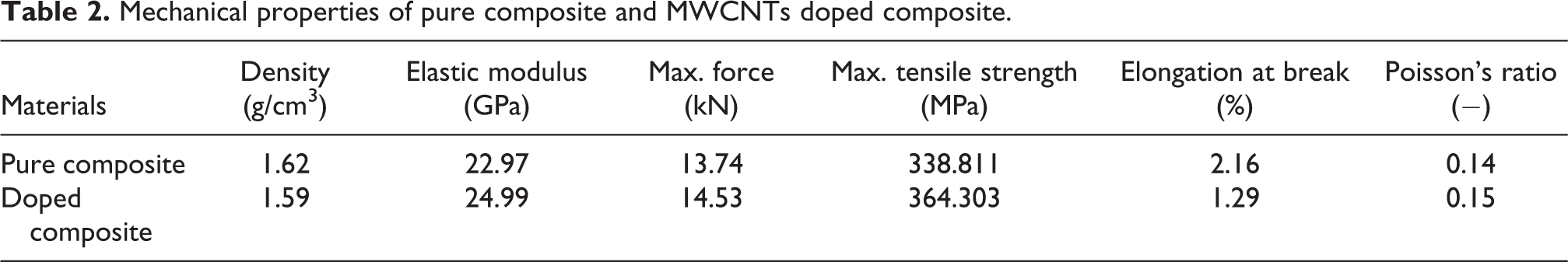
0° fibers were broken off and 90° fibers were squirmed out of according to tensile direction. Also, mechanical properties of pure composite and MWCNTs doped composite were given in Table 2. Mechanical properties of doped composite were better than pure composites. 31 Due to the transformation of the energy applied with carbon nanotube modification to extra energies such as separation of carbon nanotubes from the epoxy matrix structure, carbon nanotube breakage and crack propagation, improvements in mechanical properties occurred. The high elastic modulus and tensile strength of MWCNTs have contributed to the composite structure.
Mechanical properties of pure composite and MWCNTs doped composite.
It is emphasized in the literature that it can be added to the polymer matrix in the form of fillers to use the superior properties of CNTs.15,32-34
Burn off, density and barcoll tests
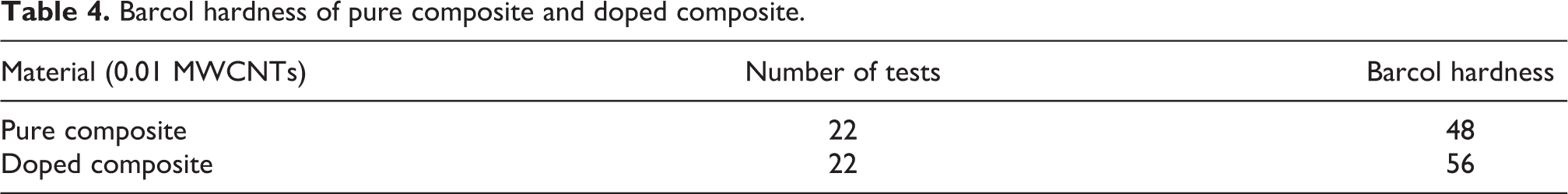
Tables 3 and 4 show the effects of MWCNTs reinforced. Fiber volume fraction, void volume fraction and surface hardness of the composite plates increased at the same time matrix volume fraction and density decreased.
Volume fractions of the pure composite and doped composite.

Barcol hardness of pure composite and doped composite.
Test parameters and results
Table 5 shows the experimental data of machinability and material removal results. The mean response refers to the average value of the performance characteristic for each parameter at different levels. Surface roughness obtained after surface milling of pure and doped composite laminates were measured with Mitutoyo Surftest SJ-310 Series portable surface roughness tester. In the measurements, Ra, Rq, Rz roughness parameters were taken into consideration and each surface was found to have different roughness.
Test data summary for machinability values and material removal results.

From the experimental results it is clear that the surface roughness increases as the feed rate increases. 35 In addition, the surface roughness decreases as the spindle revolution increases. No hardness change has seen around slots (racetrack) after material removal. Low spindle revolution and high feed rate values showed high burring. The feed of the cutting tool without enough chip removal causes burring. As seen in Table 5, delamination and splintering problems were not encountered.
Figure 3 shows that the diameter of the slots are approximately equal to the milling cutter diameter. Doped composite considerably more stable than pure composite, because slots diameters of the doped composite almost equal to end mill diameter of 6 mm. Additive MWCNTs improved the chip removal by preventing the cutting blade from flexing the material during feed. Both spindle revolution and feed rate change affected the slot diameters.
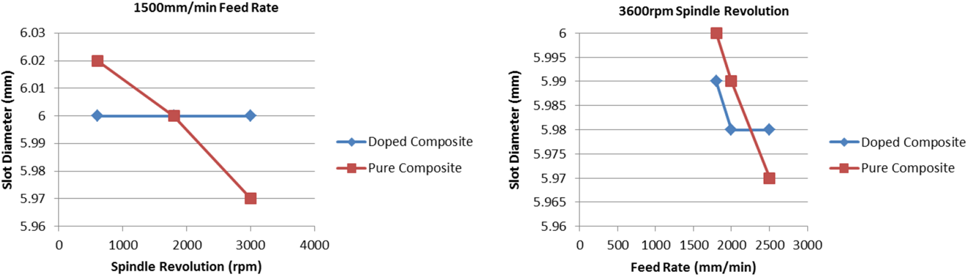
Variation of slot diameter according to spindle revolution and feed rate.
Figure 4 shows that the surface roughness is affected by spindle revolution and feed rate. 36 Many studies have made the same decision in the literature; Azmi et al. 26 reported that feed rate has the most dominant role in influencing the surface roughness, Ra, followed by spindle speed with each factor contributing 67% and 19%, respectively. The effect of depth of cut has been found to be negligible. In this study, it was found that MWCNTs additive to GFRP reduces surface roughness.
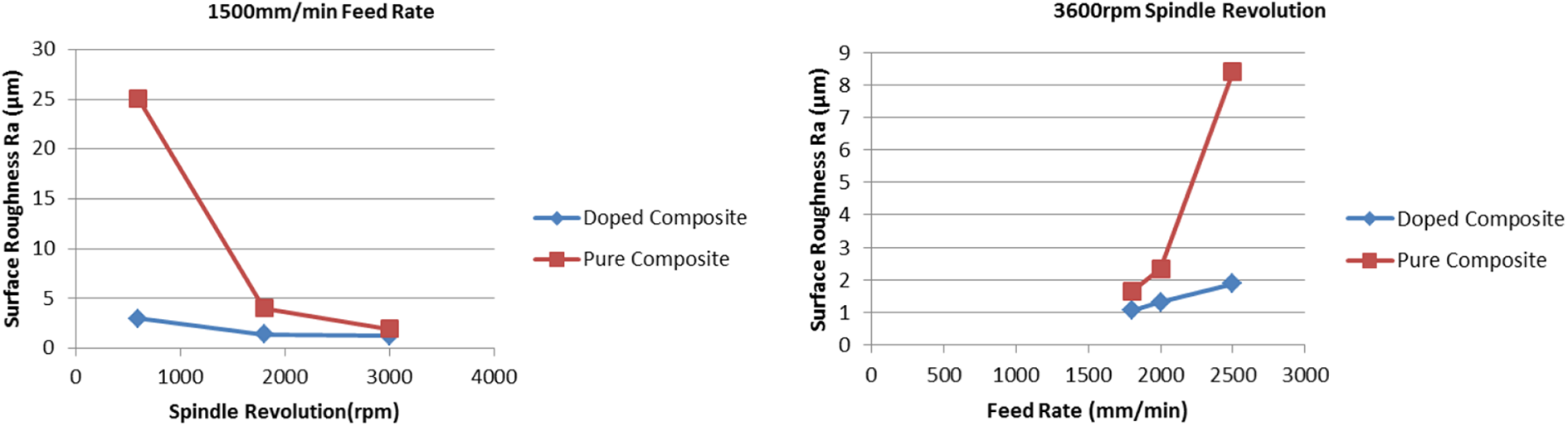
Surface roughness according to spindle revolution and feed rate.
Surface inspection by Olympus fluorescence microscope
Pure and doped composite plates were analyzed by Olympus microscope after surface milling. The Olympus BX-53 PHAKO is a stereo microscope suitable for fluorescence microscopy equipped with an Olympus XC-10 digital camera system. Burring, epoxy aggregation, fiber deflection were seen on inspected composite parts. Cooling water and air were not used to cool the cutters during face milling. Fiber deflection is thought to occur during the vacuum infusion step or during milling.
Figure 5 shows burring, epoxy aggregation and material stacking after surface milling of the pure composites layer. High spindle revolution and feed rate values are thought to cause these damages. Figure 6 shows a smooth and burr-free cut composite surface with MWCNTs doped. The MWCNTs additive has added stability to the composite structure and has prevented material accumulation and dispersion during the material removal process. Carbon nanotubes (CNTs) have high potential for the modification of glass fiber reinforced polymer (GFRP) composite laminates. 37

Surface milled pure composite layer.

Surface milled doped composite layer.
Tool wear visual examination by Zoller Genius 3s
Zoller Genius 3s is the universal measuring machine for metal cutting tools. All edges of the end mills have been inspected by Zoller Genius after surface milling. Damaged cutting edges and milling cutters were detected and analyzed. Figure 7 shows the wear in the side cutting edges of the end mill used to slot into the pure composite material. Wear was found near the cutting surface and at the end of the cutting knives.

Lateral face wear of tool cutting edge (pure composite cut).
Lateral face wear of tool cutting edge that used for doped composite cut are illustrated in Figure 8. It can be interpreted that abrasions grow from the surface to the edges. Block-shaped abrasions from the end sections of the milling knife to the body were also detected. The MWCNTs additive increased wear on the edges of the cutting tool due to carbon nanotubes are hard materials which are one of the allotropes of carbon such as diamond, graphite, fullerene. There was no breakage or cracking at the cutting edge.

Lateral face wear of tool cutting edge (doped composite cut).
Frontal plane and edge wear of the cutting tool were illustrated in Figures 9 and 10. It is obvious that epoxy, glass fiber and MWCNTs materials cause abrasion in the milling cutters.

Frontal plane and edge wear of the cutting tool (pure composite cut).

Frontal plane and edge wear of the cutting tool (doped composite cut).
Small abrasions were detected at the end parts of the milling knife which cut only the glass fiber and epoxy mixture, while larger and wide surface abrasions were found in the cutting of MWCNTs additive composite materials.
It was determined that the milling knife used in cutting of MWCNTs doped composite material had significant wear on the corners and front faces. Figure 10 shows that the wear increases with the MWCNTs additive.
Conclusion
This paper has presented and discussed the effect of nanoparticle additive on surface milling in glass fiber reinforced composite structures. The following conclusions can be drawn based on the results of the present work;
It was determined that the composite materials produced with 0.1% MWCNTs additive were stronger than the pure samples. Low density, high elastic modulus and tensile strength were obtained with nanoparticles.
Surface hardness with nanoparticle supplementation increased by 16.66%, fiber volume fraction was 1.16%, void volume fraction increased by 3.67%. On the other hand, the matrix volume fraction was 4.84%, the density was 1.85%, the composite layer thickness decreased by 6.25%.
The 0.1% MWCNTs additive reduced the surface roughness of composite structures. The surface of the test specimens with carbon nanotubes was found to be smoother and regularer than the surface of the pure composite samples. In the measurements, Ra, Rq, Rz values were decreased with nanoparticle additive.
The surface roughness is reduced as the spindle revolution increases with 1500 mm/min constant feed rate.
The surface roughness is increased as the feed rate increases with 3600 rpm constant spindle revolution.
It was observed that the milling surfaces of the MWCNTs reinforced composite layers were more burr-free than the pure composite layers and had smooth cutting edges.
Wear on the side and front cutting surfaces of the milling cutters used in the surface milling of composite materials were determined. It was determined that the milling knife opening the MWCNTs reinforced composite sheets had more wear on the pure composite layers than the cutting tool operating.
After surface milling of composite layers with and without MWCNTs, surface hardness was not changed in slot circles.
Footnotes
Declaration of conflicting interests
The author(s) declared no potential conflicts of interest with respect to the research, authorship, and/or publication of this article.
Funding
The author(s) received no financial support for the research, authorship, and/or publication of this article.