
Abstract
A growing application of polycarbonates is in the microfluidic disks and DNA detection devices, where surface finish of the micro-channels plays an important role. This study intends to investigate the tool wear and surface finish generated during micro slot milling of polycarbonate using uncoated, TiN-coated, and TiAlN-coated tungsten carbide tools. The effects of tool coating and the machining parameters on the possible reduction of tool wear and improvement of surface finish were investigated. It was found that with careful selection of cutting parameters and tool coating, micro-channels with smoother surface finish, minimum burrs around the edges, and controlled tool wear can be obtained using micro-milling. A combination of medium range of depth of cut and feed rate was found to improve the surface finish in polycarbonates, as well as minimize the tool wear. The TiAlN tool coating was found to only be effective in reducing tool wear without much effect on the machined surface. The adhesion was found to be the most dominating tool wear mechanism in uncoated carbide tool, followed by cutting edge chipping and tool nose’s plastic failure. The adhesion wear was found to be reduced in coated tools, especially in TiAlN-coated tools, although delamination wear started to dominate in the coated tools when higher feed rate and depth of cut were used. Both lower and higher of depths of cut were found to generate higher tool wear and leave traces of tool marks on the machined surface.
Introduction
Polycarbonates are a group of thermoplastic polymers used widely for optical applications due to their high optical transparency, outstanding impact resistance, high strength, and high toughness. 1 However, the applications of polycarbonates are not limited to optical applications only. Another growing application of polycarbonates is in the microfluidic disks and DNA detection devices because of their optical transparency and high strength.2–4 During the application in microfluidics, high quality micro-channels are fabricated on the surface of polycarbonate glass. 5 To ensure the smooth flow of the drug and any other fluids used, the surface finish of the micro-channels is the most important requirement in microfluidics device. 6 Micro injection molding is one of the most widely used manufacturing processes for fabricating micro parts and components in polymers including polycarbonates. 7 Micro additive manufacturing or 3D printing is another popular option for creating micro molds and other complex parts using polymers. 8 Currently, there are various techniques for fabricating the micro-channels on the microfluidic disks and devices, such as photolithography and etching. 9 However, the lithography-based microfabrication processes are slow, expensive, and involve hazardous chemicals, and thus, not suitable for mass production of microfluidic disks.1,4 In order to find the alternative solutions for making polycarbonate microfluidic disks with high quality micro-channels, researchers have investigated the feasibility of applying various non-conventional and conventional machining processes to manufacture micro-channels on polycarbonates. Among the non-conventional machining processes, laser machining10–16 and abrasive water jet machining (AWJM)17–19 are two common processes used to machine polycarbonate glass by the previous researchers. However, both processes impose some challenges and limitations when being used to machine polycarbonates. The laser machining results in heat-affected zone (HAZ) around and underneath the machined features. On the contrary, AWJM has limitations to miniaturization, as the size of the micro-channels or part is limited by nozzle size, which must be bigger than the abrasive particle size.
In order to find alternative processes of machining polycarbonates, conventional mechanical micromachining processes are being approached. Bolat 1 carried out the machinability study of polycarbonate in single-point diamond turning (SPDT) process by assessing the effect of machining parameters and vibration on the surface finish of the polycarbonate for optical applications. With the optimal machining parameters, average surface roughness as low as 2.7 nm was obtained in polycarbonate, making the optimized process suitable for the fabrication of optical lenses. Khatri et al. 20 experimentally optimized the machining conditions in SPDT of polycarbonate with a goal of achieving nano-level surface finish and high profile accuracy. They reported that tool feed rate was the most dominant parameter, followed by spindle speed that influenced the surface finish, whereas the profile accuracy was substantially influenced by the depth of cut. Saini et al. 21 carried out optimization of machining parameters during ultra-precision SPDT of polycarbonate with a focus of obtaining improved surface finish and developed an empirical formula relating the surface finish to the machining parameters, such as spindle speed, depth of cut, and feed rate. Gindy 22 carried out SPDT of polycarbonate and nylon and developed an empirical shear angle relationship by applying the minimum energy criterion for yielding of polymer. Singh et al. 23 carried out SPDT of polycarbonate and investigated how the surface roughness and waviness of the machined profile varied with machining time and length of cut. It was found that the tool wear dominantly increased surface roughness and waviness over time and length of machining. Barwasser 24 developed a turning tool to machine the edges of the polycarbonate lenses and connected the tool co-axially with a grinding wheel, which provided the rough grinding, fine grinding, and beveling. The turning tool was used to minimize the material from the edge of the lenses to achieve accurate dimensions of the lenses. Rafaelli 25 developed a process and equipment to machine the edge of the polycarbonate lenses as well as for polishing the surface with a diamond wheel. The proposed innovative process allowed completing the fabrication of lenses in a single machine with both polishing and edging to the accurate dimensions. Langlois and Lecerf 26 developed a grinding tool to machine and bevel polycarbonate glass lenses. The proposed tool was able to minimize the clogging at the cutting tool than traditional machining of polycarbonate experiences and was able to obtain comparatively smoother surface finish than traditional machining. Srinivasan et al. 27 assessed the effect of machining parameters and cutting forces on the delamination of fibers in drilling glass fiber–reinforced polycarbonate composite. It was found that the feed rate influenced the delamination the most and that delamination could also be controlled by proper monitoring of the cutting forces generated in the drilling process. Kuram 28 investigated the machinability of glass fiber–reinforced and regular polypropylene using the micro-milling process. It was reported that both the cutting forces and tool wear were higher for machining-reinforced polymer compared to that of unreinforced polymer. They concluded that unreinforced polymer provides better micro-machinability compared to glass fiber–reinforced polymers.
In recent years, a few research studies have focused on machining of micro-channels on polycarbonate using the micro-milling process. Chen et al. 29 experimentally evaluated how machining parameters influenced the surface roughness of machined micro-channels in micro-milling polycarbonate. They were able to obtain average surface roughness of 127 nm when using the spindle speed of 20,000 r/min in conjunction with feed rate of 300 mm/min and depth of cut of 10 µm. Samuel et al. 30 conducted a comprehensive experimental investigation into the machinability of carbon nanotube (CNT)-reinforced polycarbonate nanocomposite using micro-milling and compared against those with plain polycarbonate and a carbon fiber–reinforced composite. It was reported that among these three materials, machining CNT-reinforced polycarbonate nanocomposite resulted in the smoothest surface, which was mainly due to the relatively high thermal conductivity of the CNT. In another study by Dikshit et al., 31 a continuum-based model was developed to simulate the microstructure for CNT-reinforced polycarbonate nanocomposite at different loadings of CNT. They conducted compression tests with varied strain rates to validate the model for machining-induced microstructure changes. It turned out that the model could predict the yield behavior of the nanocomposite within 10% accuracy. Singh and Kumar 32 carried out modeling and experimental investigation on the machining performance of CNT-reinforced epoxy/glass fabric polymer composite in drilling process. It was found that both surface roughness and delamination reduce with the increase of CNT content in the matrix, with lowest value of surface roughness obtained at 1.5 wt% multi-walled carbon nanotube (MWCNT)-embedded epoxy/glass fabric polymer composite. In addition to machining of polycarbonate, polypropylene, and epoxy matrix composites with various reinforcements, there have been several recent studies on machinability of carbon fiber–reinforced polymer (CFRP) composites. Majority of the research studies have focused on investigating the drilling performance of CFRPs,33–36 while few studies have focused on milling machinability of CFRPs.37,38
Although there have been several studies on the SPDT and grinding of polycarbonates, the focused application area was optical lenses. There have been very few studies focusing on another promising application of polycarbonate, which is in microfluidics. For microfluidic disks and device fabrications, obtaining high quality micro-channels is important to maintain smooth flow of the fluids and drugs. Although there have been several research studies on micro-milling of other polymers and their composites, very few studies focused on micro-milling performance of polycarbonates. This research aims to investigate two important aspects of the micro-milling of polycarbonate, that is, tool wear and surface quality.
Experimental setup and method
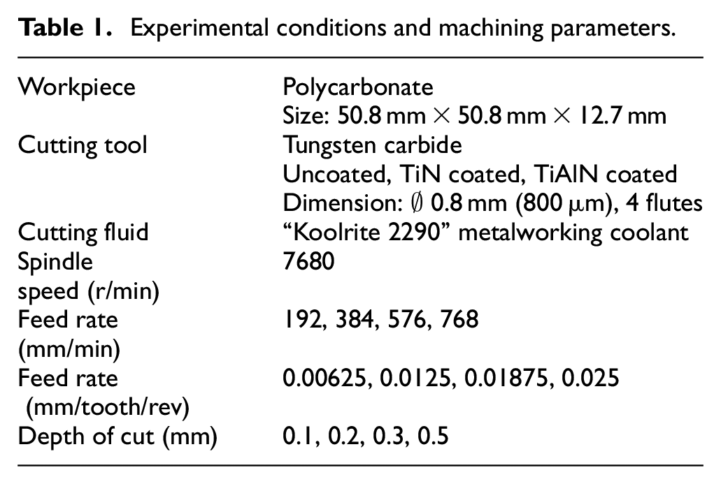
The experimental trials on micro-milling of polycarbonate were conducted using a HAAS CNC mini-milling machine using uncoated, TiN-coated, and TiAlN-coated carbide tools. The nominal diameter of the cutting tool is 0.8 mm. The specifications for the workpiece and end mills, as well as machining conditions, are given in Table 1. The spindle speed was kept constant at 7680 r/min throughout the study, as this is near the maximum capacity of the spindle. The depth of cut was varied for 0.1, 0.2, 0.3, and 0.5 mm, and the feed rate was varied for 192, 384, 576, and 768 mm/min (0.00625, 0.0125, 0.01875, and 0.025 mm/tooth/rev, respectively). For each combination of cutting speed, feed rate, and depth of cut, three slots of 25.4 mm length were machined. After machining, all the slots were analyzed under optical microscope, and some selected slots were analyzed using atomic force microscope (AFM). Olympus SZX-12 optical microscope equipped with fluorescence stereoscope system was used to take images of the machined slots, focusing on surface topography and burrs at the edges separately. The images of cutting tools were analyzed using scanning electron microscope (SEM) for the identification of tool wear mechanisms. The energy-dispersive X-ray spectroscopy (EDS) was used to retrieve elemental information on the cutting tool edges and flank faces to explain the tool wear mechanisms.
Experimental conditions and machining parameters.
Results and discussions
Tool wear analysis
During the micro-milling of polycarbonate, the dominating tool wear mechanisms are found to be different from those usually seen in metal machining. Unlike the gradual abrasion wear found in traditional metal micromachining, there has been a combination of various tool wear mechanisms found on the same tool. The common tool wear mechanisms that dominate micro-milling were found to be adhesion, chipping, plastic deformation, and catastrophic failure. Although flood coolant machining was used to run all the experiments on micromachining of polycarbonate, a significant amount of adhesion on the cutting tool was still observed. The adhesion of chips was observed both at the cutting edges and on flank and rake faces. Figure 1 presents the SEM images of cutting edges near the tool nose of uncoated carbide tools at 0.1 and 0.5 mm depth of cut. Other parameters were kept constant at spindle speed of 7680 r/min and feed rate of 192 mm/min. It was found that for both cases, there were adhesions of re-solidified chips of polycarbonates on the cutting edges. This may be due to comparatively lower glass transition temperature of the polycarbonate, which is about 147°C. 1 The polycarbonate starts softening above this temperature and comes into flow region at and above 155°C. 1 Higher depths of cut usually result in higher tool temperatures, which are above the glass transition temperature of the polycarbonate, thus resulting in melting and re-solidification of chips on the cutting edges and tool flank faces.
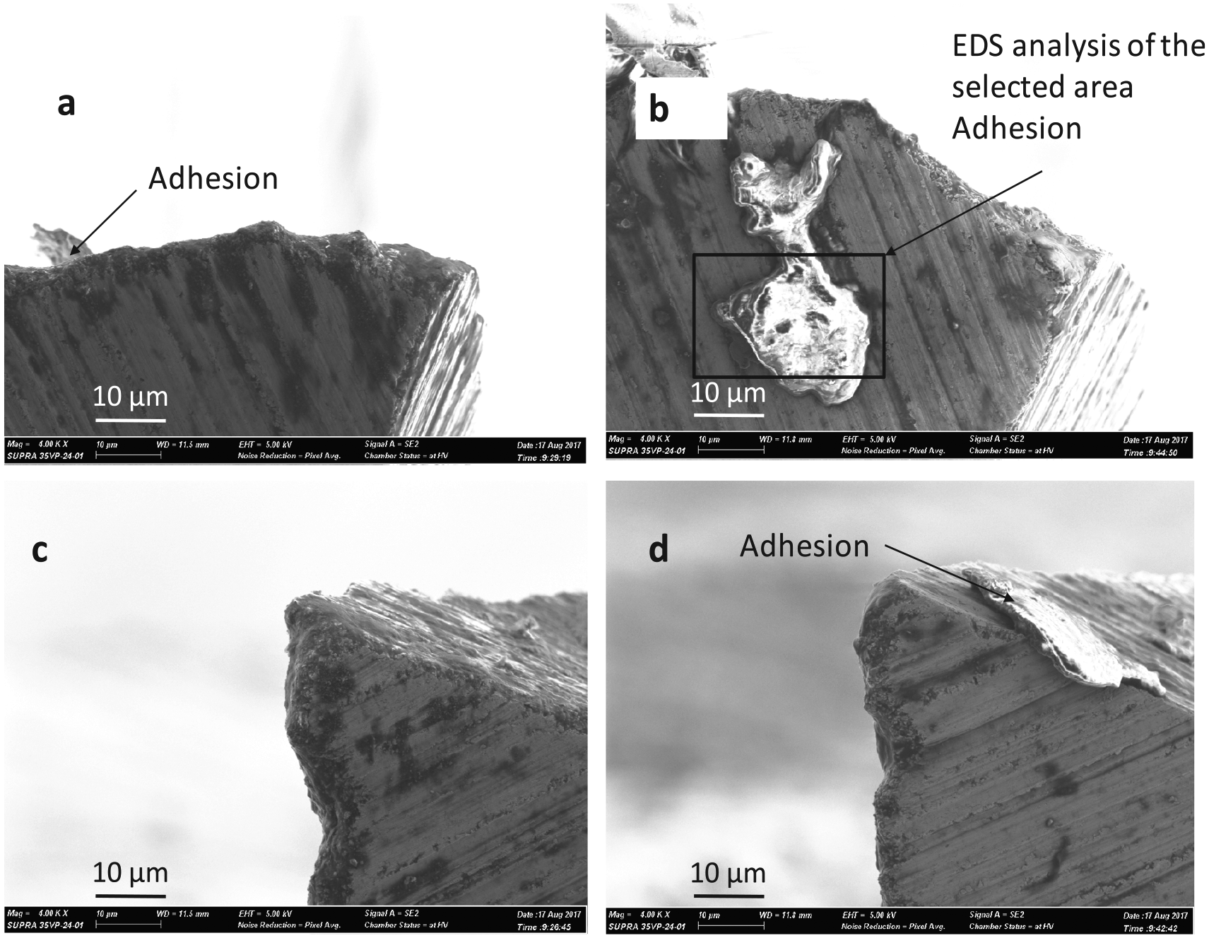
SEM images of cutting edge and nose of the uncoated carbide tools after machining: (a) and (c) 0.1 mm depth of cut and (b) and (d) 0.5 mm depth of cut (constant parameters: uncoated carbide tool, feed rate of 192 mm/min, and spindle speed of 7680 r/min).
EDS analysis was conducted to investigate the constituents of the adhesion (the deposited debris) on the cutting tool. Figure 2 shows the EDS spectrum analysis of the adhered debris shown in Figure 1(b). The EDS analysis reveals tungsten (W) and cobalt (Co) as the major constituents in addition to some minor elements. The mass percentages of W and Co from the spectrum analysis were found to be 90.84% and 8%, respectively. All other constituents combined made 1% of the total mass considered in the analysis. This may be due to the fact that the polycarbonate chips are electrically non-conductive, and hence was charged when imaged and analyzed under electron beam. The white color of debris in Figure 1(b) indicates the charging of the debris during the SEM imaging. As a result, only electrically conductive elements were found in the EDS analysis. W and Co reveal the composition of the cutting tool, and the other elements such as Na, Ca, Cr, and Al may indicate small amount of impurities in the cutting tool or in the polycarbonate, as some of those impurities are known to exist in the traditional glass materials.
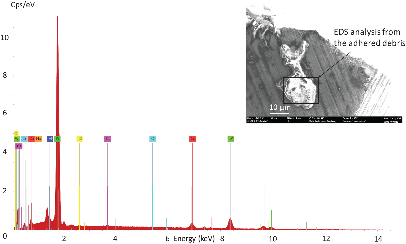
EDS spectrum analysis of the adhered debris attached to the cutting tool, as shown in Figure 1(b).
One interesting observation in the polycarbonate machining is that once the polycarbonate comes in the flow region, the higher feed rates were found to be more effective in reducing cutting force and minimizing the tool wear. This might be due to the fact that it requires higher tool speed to cut through the polymeric materials when it is in the flow region, which also minimizes localized heat accumulation that could further increase the fluidity of the polycarbonate. Figure 3(a)–(c) illustrates the effect of feed rate on the tool wear for uncoated carbide tools at a fixed depth of cut of 0.5 mm and 7680 r/min of tool spindle speed. It is manifest that when machining at higher depth of cut, the adhesion decreased as the feed rate increased for uncoated carbide tools. This finding of polycarbonate machining is different from that of traditional metal machining process, where usually the adhesion increases significantly with the increase of feed rate. Figure 3(d)–(e) presents the images of cutting tools after machining at different feed rates at low depth of cut of 0.1 mm. It was found that for all feed rates, the adhesion of chips to the cutting edges and flank faces of the tools is lower at depth of cut 0.1 mm than the tools used at depth of cut of 0.5 mm.
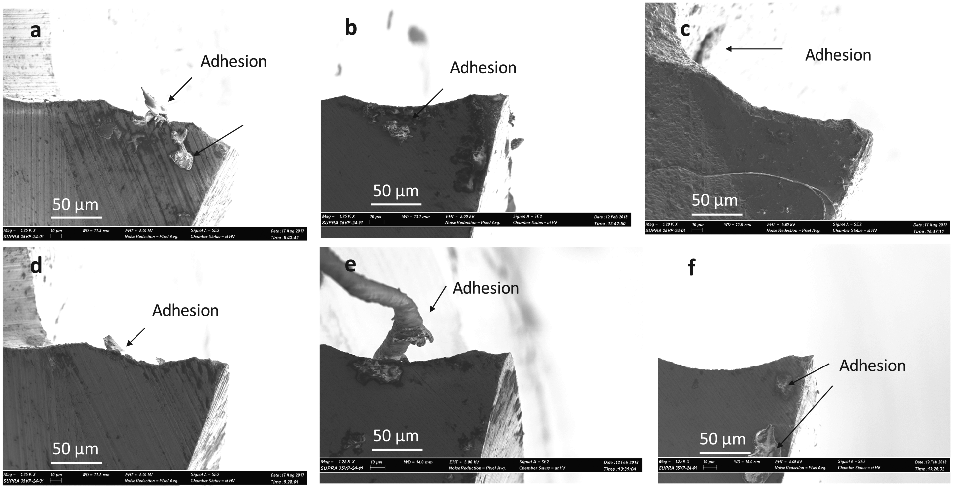
Effect of feed rate on the adhesion wear on the uncoated carbide tool: (a) f = 192 mm/min, (b) f = 384 mm/min, (c) f = 786 mm/min (constant parameters for (a)–(c): depth of cut = 0.5 mm, spindle speed = 7680 r/min), (d) 192 mm/min, (e) 384 mm/min, and (f) 786 mm/min (constant parameters for (d)–(f): depth of cut = 0.1 mm, spindle speed = 7680 r/min).
To investigate the effectiveness of tool coatings on the reduction of adhesion wear on the cutting tool, TiN- and TiAlN-coated tools after machining with the same machining conditions were analyzed. Figure 4 illustrates the comparison of the adhesion tool wear for uncoated, TiN-coated, and TiAlN-coated carbide tools for two different depths of cut (0.1 and 0.5 mm) at a constant feed rate and r/min. It is manifest that for both depths of cut, the adhesion was higher at the cutting edges and flank faces of the uncoated carbide tools. Both TiN- and TiAlN-coated tools were found to have lesser adhesion to the cutting tools, indicating the effectiveness of tool coating in reducing adhesion wear. The improvement of adhesion wear with the coated tools may be associated with the reduced frictional coefficient of the TiN- and TiAlN-coated tools compared to traditional uncoated tungsten carbide (WC) tools. 39 The lower friction coefficient generates comparatively lower amount of heat due to friction at the tool–chip and tool–workpiece interfaces, thus minimizing the tool temperature and amount of adhesion to the cutting tool.
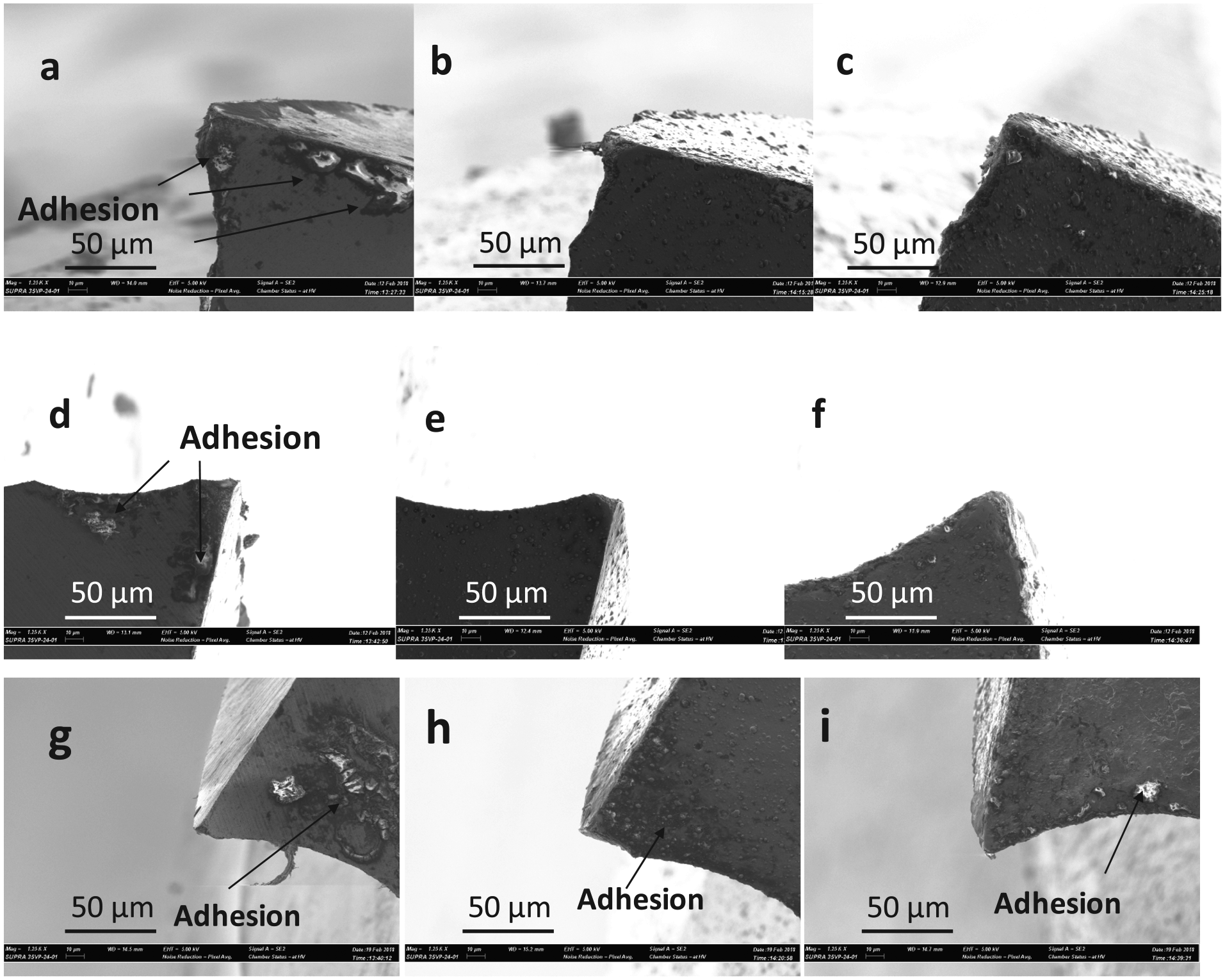
Comparison of the adhesion tool wear between uncoated ((a),(d),(g)), TiN-coated ((b),(e),(h)), and TiAlN-coated ((c),(f),(i)) carbide tools at different settings; (a)–(c) feed rate of 384 mm/min and depth of cut of 0.1 mm, (d)–(f) feed rate of 384 mm/min and depth of cut of 0.5 mm, and (g)–(i) feed rate of 576 mm/min and depth of cut of 0.5 mm (fixed parameter: spindle speed of 7680 r/min).
Figure 4 illustrates the comparisons of the adhesion wear among uncoated, TiN-coated, and TiAlN-coated carbide tools for two different feed rates, 384 and 576 mm/min. The depth of cut and tool rotational speed were kept constant at 0.5 mm and 7680 r/min, respectively. For both feed rates, uncoated carbide tools resulted in higher adhesion of chips to the cutting edge and tool faces. Although there was deposition of very small fractions of chips on the flank face of the cutting tool, no significant adhesion was observed in either TiN- or TiAlN-coated carbide tools. Among two coatings, TiAlN coating was found to be more effective in reducing adhesion to the cutting edges, as well as minimizing wear at the tool cutting edge and tool nose.
Abrasion wear is one of the most commonly seen forms of tool wear in all types of machining. However, it was difficult to label abrasion wear during machining of polycarbonate, as most of the abrasion wears were found to be associated with the chipping wear. The abrasion wear results from the friction between the cutting edge and the workpiece during machining processes. The abrasion is typically a gradual wear that results in rounding of the cutting edges, thus leading to more severe forms of tool wear, such as chipping and catastrophic failure. 40 Figure 5(a)–(c) illustrates the abrasion wear on cutting edges for various depths of cut and feed rates for uncoated carbide tools. It was found that the abrasion and minor chipping occurred simultaneously on the cutting edges for various depths of cut and feed rates. Due to abrasion and chipping, the cutting edges become rounded and lose their sharpness, resulting in higher cutting forces and plastic deformation or more catastrophic failure. In addition, there is a specific trend of chipping from edges making the surface irregular in the form of periodic chipping. This may induce chatter and vibration, resulting in chipping of a bigger portion of cutting edge or tool nose, especially when machining at higher depth of cut and feed rate, as can be seen in Figure 5(d)–(f). It has been found that for machining at higher feed rates and depths of cut, complete chipping of tool nose may occur for uncoated carbide tools and eventually result in catastrophic failure of the tool from the shank. Figure 5(d) and (e) shows the chipping off of tool nose during machining at 384 and 576 mm/min feed rates at depth of cut of 0.1 mm. The chipping wear of tool nose at low depth of cut of 0.1 mm may be associated with the dragging action of the cutting tool that results in plowing action rather than cutting, thus increasing the cutting forces significantly and resulting in chipping of tool nose. In addition, at the higher depth of cut, due to more materials to be removed the cutting tool, severe form of plastic deformation along with chipping was observed, as revealed in Figure 5(f).
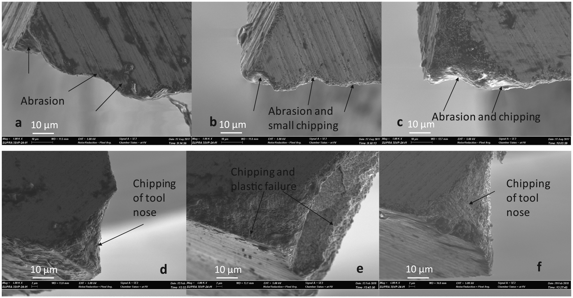
Abrasion ((a)–(c)) and chipping ((d)–(f)) wear in the cutting edges of uncoated carbide tools at different depths of cut and feed rates: (a) f = 192 mm/min and d.o.c. = 0.1 mm, (b) f = 192 mm/min and d.o.c. = 0.5 mm, and (c) f = 768 mm/min and d.o.c. = 0.5 mm; (d) f = 384 mm/min and d.o.c. = 0.1 mm, (e) f = 384 mm/min and d.o.c. = 0.5 mm, and (f) f = 576 mm/min and d.o.c. = 0.1 mm (fixed parameter: spindle speed of 7680 r/min).
Figure 6 illustrates the comparison of tool wear between the uncoated and coated carbide tools. It was found that although chipping was reduced slightly, there are signs of plastic deformation and delamination of tool coatings on the coated carbide tools. Among the three types of tools, TiN tool coating was found to be more effective in reducing chipping wear, however, at the expense of plastic deformation of the cutting edges. One important observation from Figure 6(f) is the delamination of TiAlN tool coating from the cutting tool nose when machining at a feed rate of 768 mm/min and depth of cut of 0.1 mm. Upon the removal of tool coating, the cutting tool also suffered from chipping. For both cases shown in Figure 6, at the cutting edge near the tool nose, TiAlN-coated tools showed some signs of chipping.
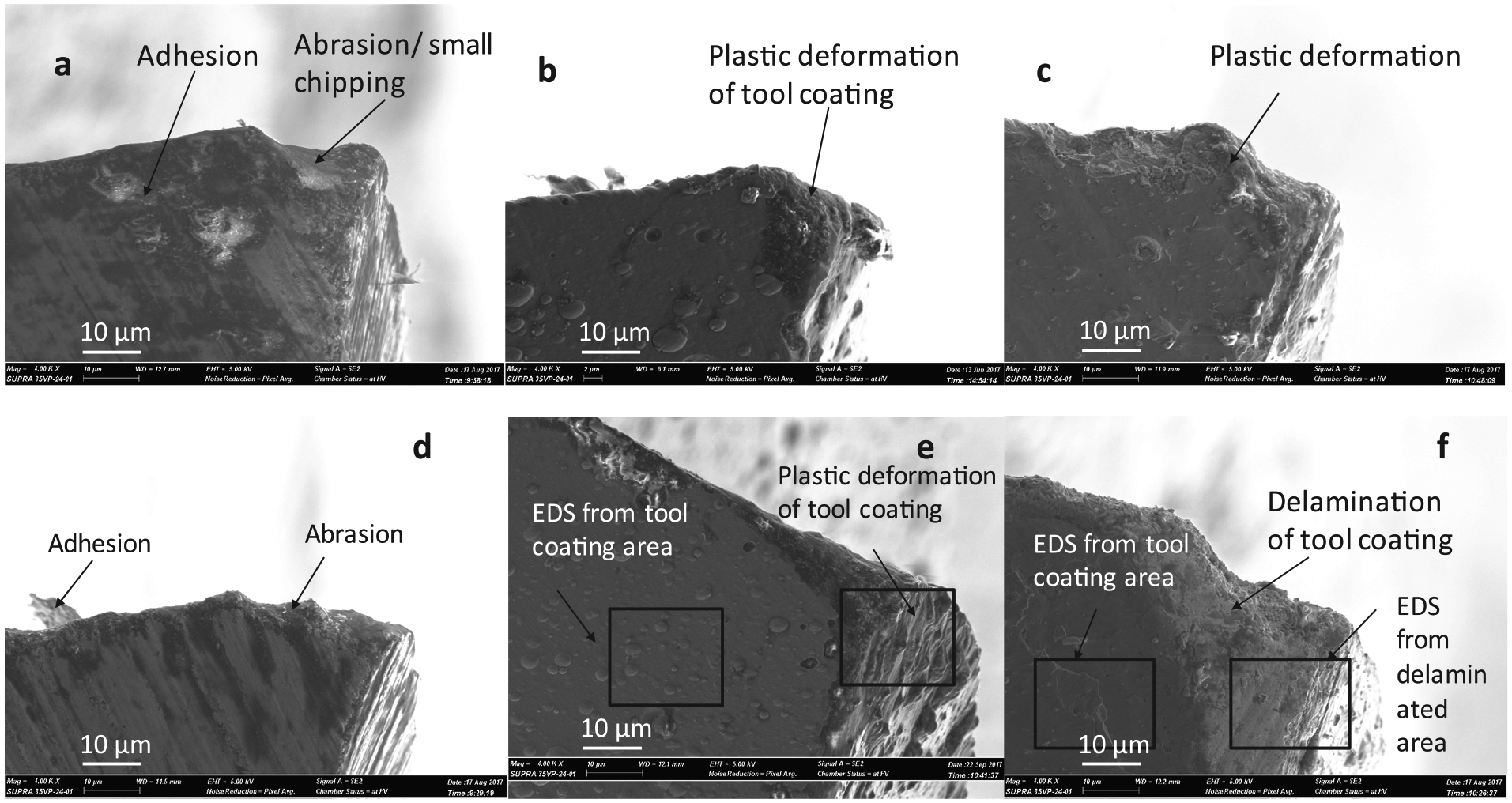
Comparison of the tool wear for uncoated ((a) and (c)), TiN-coated ((b) and (d)), and TiAlN-coated ((c) and (f)) carbide tools at various settings; (a)–(c) feed rate of 768 mm/min and d.o.c. of 0.5 mm and (d)–(f) feed rate of 192 mm/min and d.o.c. of 0.1 mm (constant parameter: spindle speed of 7680 r/min).
Figure 7 illustrates the EDS analysis results of the TiN-coated tool shown in Figure 6(e). The EDS analysis was conducted on these two selected regions of the tool. The EDS analysis results from the unaffected zone of the tool, as shown in Figure 7(a), indicate the presence of coating materials, which are mainly titanium (Ti) and nitrogen (N). There are some minor amounts of W, which confirms the presence of W beneath the TiN coating. On the contrary, the EDS analysis results of the plastically deformed zone, as shown in Figure 7(b), indicate the presence of comparatively higher percentage of W along with Co and other elements, which may migrate from the chips and/or cutting fluids. In addition, the elements of the coating material are also confirmed to be present via the EDS analysis. The elemental constituents found in the EDS analysis results of plastically deformed surface suggest melting and re-deposition of the tool coating along with chips, tool materials, and foreign substances migrated from the cutting fluid.
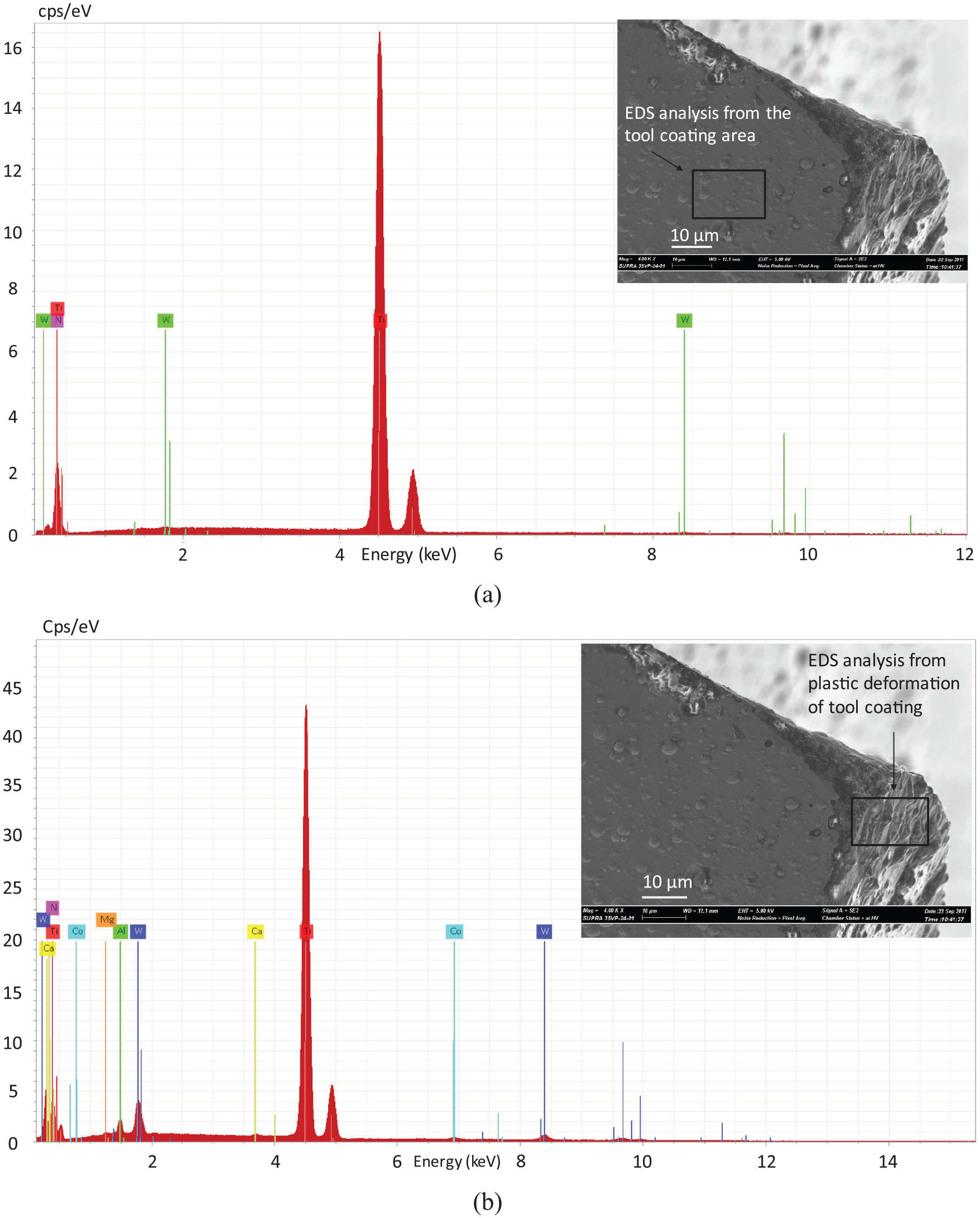
EDS analysis results of the TiN-coated tool shown in Figure 6(e) from two regions; (a) unaffected zone (tool coating) and (b) affected plastically deformed zone, as indicated by the selected boxes in Figure 6(e) (machining parameters: spindle speed of 7680 r/min, feed rate of 192 mm/min, d.o.c. of 0.1 mm, TiN-coated tool).
Figure 8(b) illustrates the EDS spectrum image obtained for the delaminated portion of the TiAlN-coated tools shown in Figure 6(f). The EDS spectrum analysis results confirm that the tool surface has rich amount of W (75.62%) along with Co (13.90%). Besides, there are minor amounts of the coating materials, such as titanium, aluminum, and chromium (all of the constituents together make only 0.74%). On the contrary, the EDS analysis results for the inside of the same tool, as seen in Figure 8(a), reveal a different composition of elements on the surface. The EDS analysis results on the unaffected tool surface confirm the presence of TiAlN coating rather than the base WC material inside. The elemental analysis shows 60.93% of titanium (Ti) and 21.23% of aluminum (Al), which are the two major constituents of the tool coating. Only a small percentage of W (1.15%) was found on the coated tool surface, which indicates the presence of base WC material.
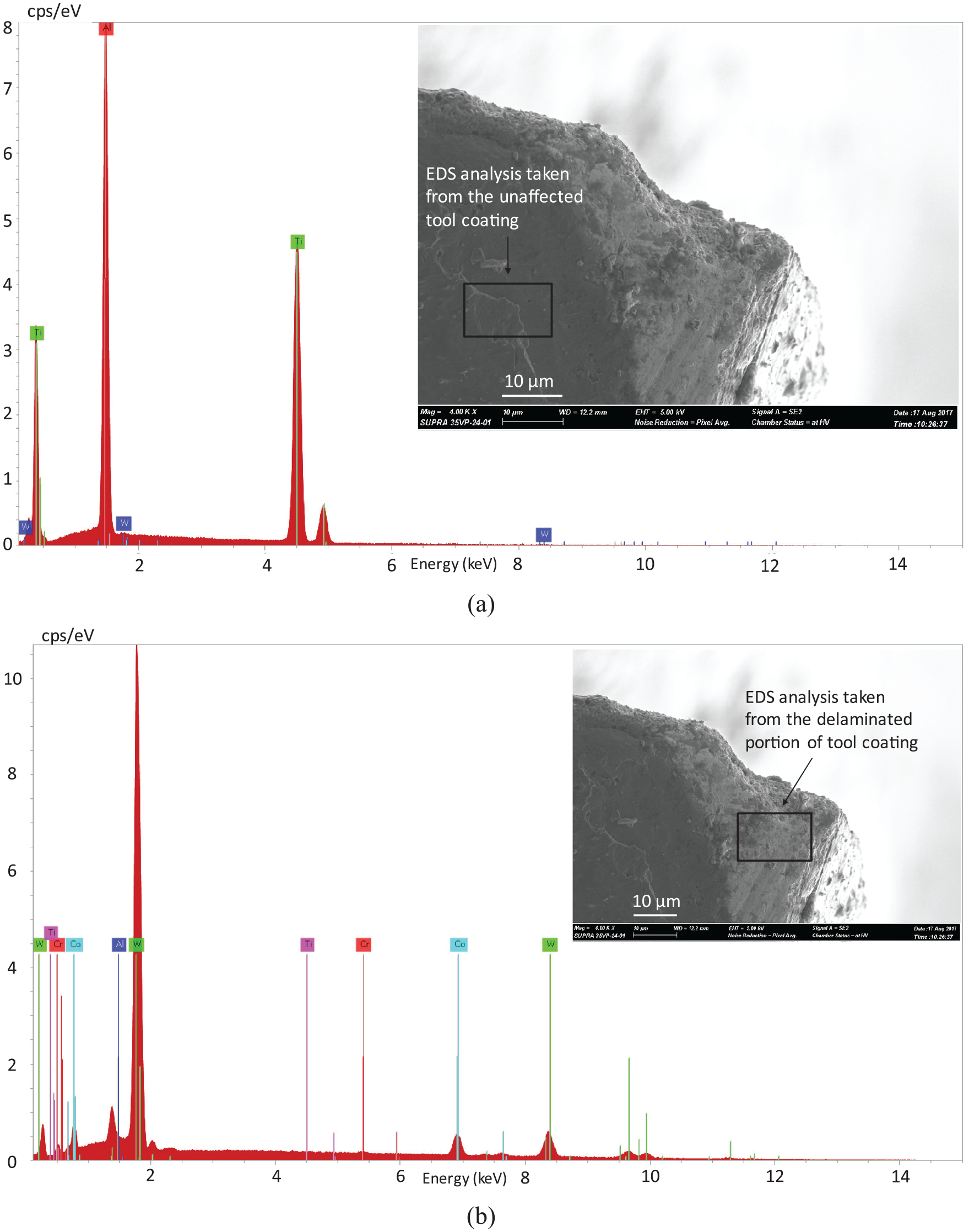
EDS spectrum analysis results of the TiAlN-coated tools from two regions; (a) unaffected tool surface (tool coating) and (b) delaminated tool surface, as indicated by the selected boxes in Figure 6(f) (machining parameters: spindle speed of 7680 r/min, feed rate of 192 mm/min, d.o.c. of 0.1 mm, TiAlN-coated tool).
Analysis of surface finish
Achieving high quality surface finish in polycarbonate glass was found to be challenging. Like traditional glass materials, machining of polycarbonate glass resulted in brittle fractures on the machined surface. In addition, the burrs and traces of tool marks on the machined surface were found to be very common features of polycarbonate machining. Figure 9 illustrates how the depth of cut and feed rate influence the surface topography during micro-milling of polycarbonate using uncoated carbide tools. It was found that for all the depths of cut and feed rates, the signs of feed mark and evidence of brittle fracture were observed on the machined surface. Interestingly, the surface became slightly smoother with fewer burrs at comparatively higher depths of cut, as observed from Figure 9(a)–(d). This is due to the fact that at lower depth of cut, there may be some dragging action of the tool face with the machined surface. The dragging of tool results in plowing action of material removal from the bottom of the cutting tool, rather than removing the material from the cutting edges. However, there was very minimal difference on the surface finish for various depths of cut. Figure 9(e)–(h) illustrates how the feed rate influences the surface quality. An obvious finding is that as the feed rate increases, the surface becomes rougher due to the increased tool marks. However, the minimum amount of burrs and signs of less brittle fracture were observed at the feed rate of 384 mm/min, as shown in Figure 9(e)–(h). This also proves the finding from the tool wear section that lowest settings of depth of cut and feed rate may not provide the best surface finish and reduced tool wear, unlike traditional machining of metallic materials. Rather, slightly higher settings than the lowest available setting promotes more ductile mode machining, thus resulting in improved surface finish and lower tool wear in micro-milling of polycarbonate glass.
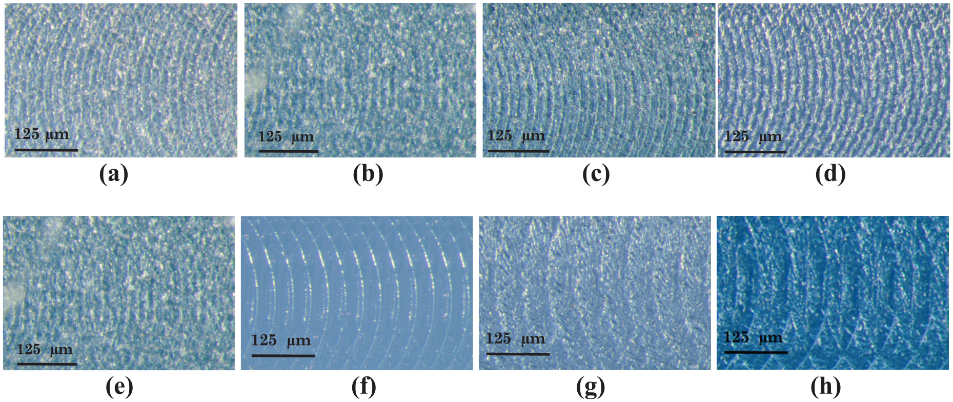
Optical images of the machined surface obtained using uncoated carbide tool at various depths of cut (a)–(d) and feed rate (e)–(h); (a) 0.1 mm, (b) 0.2 mm, (c) 0.3 mm, and (d) 0.5 mm (constant parameters for (a)–(d): spindle speed = 7680 r/min, f = 192 mm/min); (e) 192 mm/min, (f) 384 mm/min, (g) 576 mm/min, and (h) 768 mm/min (constant parameters for (e)–(h): spindle speed = 7680 r/min, d.o.c. = 0.2 mm).
To investigate the effectiveness of tool coatings on the improvement of surface finish, the surface finish obtained using TiN- and TiAlN-coated carbide tools at different parametric combinations are illustrated Figure 10. It was found that both TiN and TiAlN coating were effective in reducing brittle fracture and the traces of the cutting tool on the machined surface. The improvement of surface finish was mainly associated with the reduction of brittle fracture and burrs on the machined surfaces. The improvement of surface finish for TiN-coated tools was mostly significant at depth of cut of 0.5 mm. However, the improvement was very obvious for TiAlN-coated tools for all depths of cut, especially at depths of cut of 0.1 and 0.3 mm. It can be seen from Figure 10 that TiN-coated tools provided surface with minimal burrs and tool marks at 0.5 mm depth of cut. On the contrary, TiAlN provided best machined surface at 0.3 mm depth of cut. The findings from Figure 10 go on to prove that the tool coating may be more effective at comparatively higher depth of cut while machining polycarbonate glass.
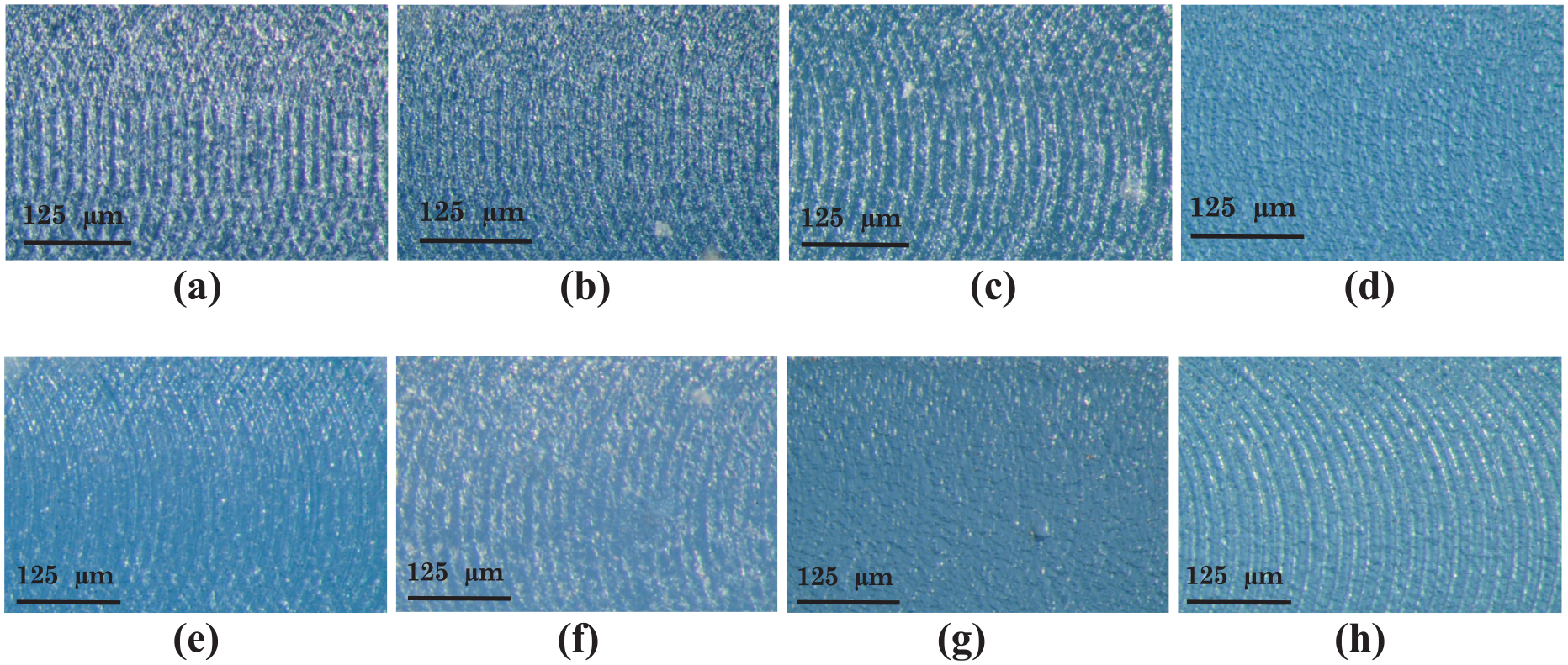
Optical images of the machined surface obtained using TiN-coated carbide tools ((a)–(d)) and TiAlN-coated carbide tools ((e)–(h)) at various depths of cut; (a) and (e) 0.1 mm, (b) and (f) 0.2 mm, (c) and (g) 0.3 mm, and (d) and (h) 0.5 mm (constant parameters: spindle speed = 7680 r/min, f = 192 mm/min).
Figure 11 illustrates the side-by-side comparisons of the machined surface finish obtained by uncoated, TiN–coated, and TiAlN-coated carbide tools at two different combinations of machining parameters. It was found that for both settings of parameters, the coated carbide tools generated smoother surface finish with fewer marks of brittle fractures than uncoated carbide tools. It was also found that for both cases, TiN-coated tools resulted in smoother surface finish followed by TiAlN-coated tools. The average surface roughness value (Ra) was not measured for the machined slots, as the existing stylus of the Mitutoyo surface roughness tester could not reach the bottom of the slot due to smaller width and higher depth of the micro-channels. The non-contact surface roughness measurement devices, such as white light interferometer, could be an option, but, currently, the accessibility to this device is lacking. However, a few AFM images on the machined surface were presented to provide an idea about the surface roughness. Figure 12(a) illustrates the AFM image taken from the machined surface obtained using TiAlN tool at a parameters combination of spindle speed of 7680 r/min, feed rate of 384 mm/min, and depth of cut of 0.2 mm. In order to get line surface roughness, a line was drawn from left to right along which the line profile was presented, as indicated in Figure 12(b). The average surface roughness along the line was found to be 3.31 nm, with a standard deviation of 0.5 nm.
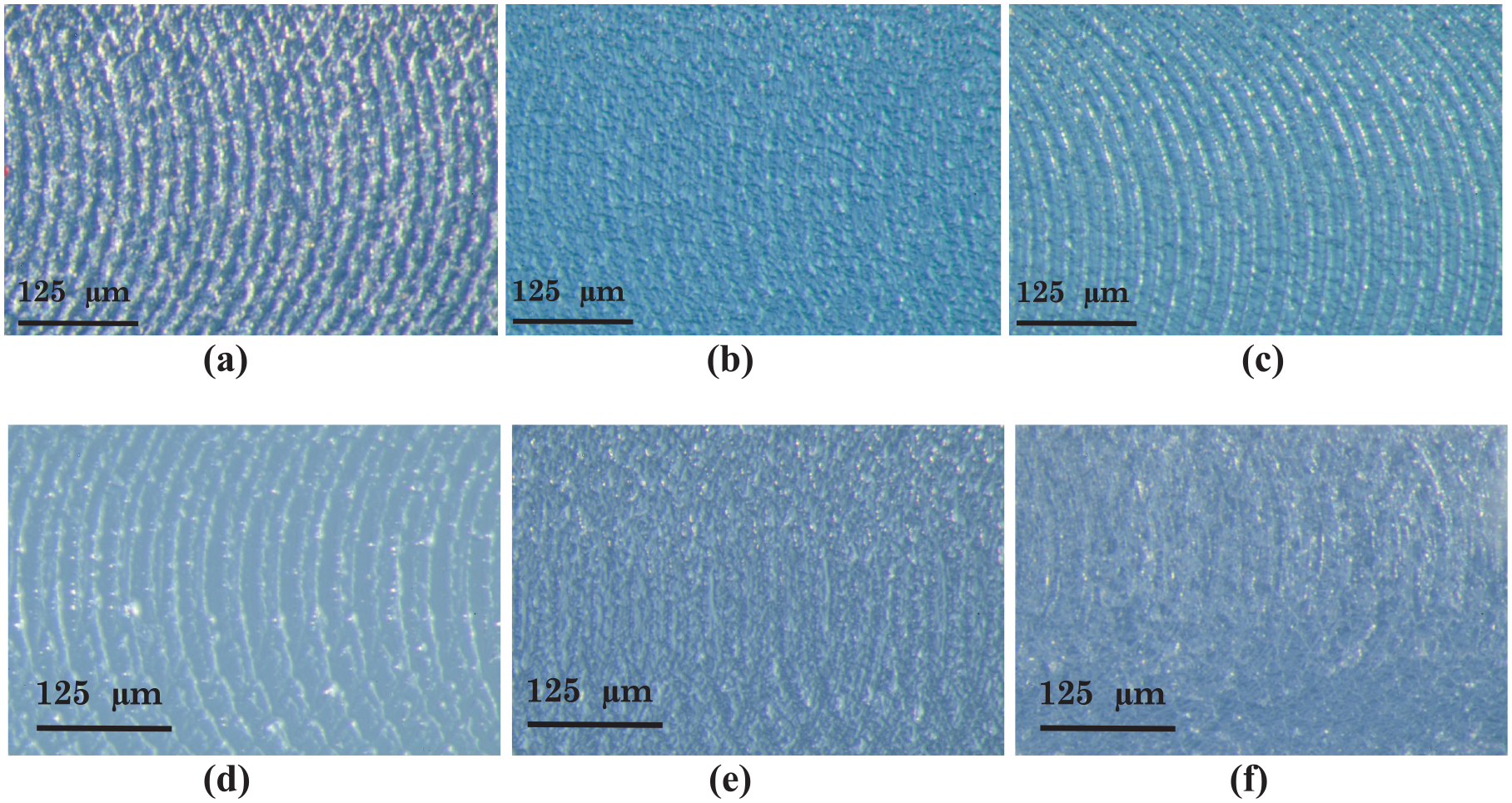
Comparison of surface finish generated by uncoated ((a) and (c)), TiN-coated ((b) and (d)), and TiAlN-coated ((c) and (f)) carbide tools at different parametric combinations; (a)–(c) f = 192 mm/min, d.o.c. 0.5 mm and (d)–(f) f = 384 mm/min, d.o.c. 0.2 mm (constant parameters: spindle speed of 7680 r/min).
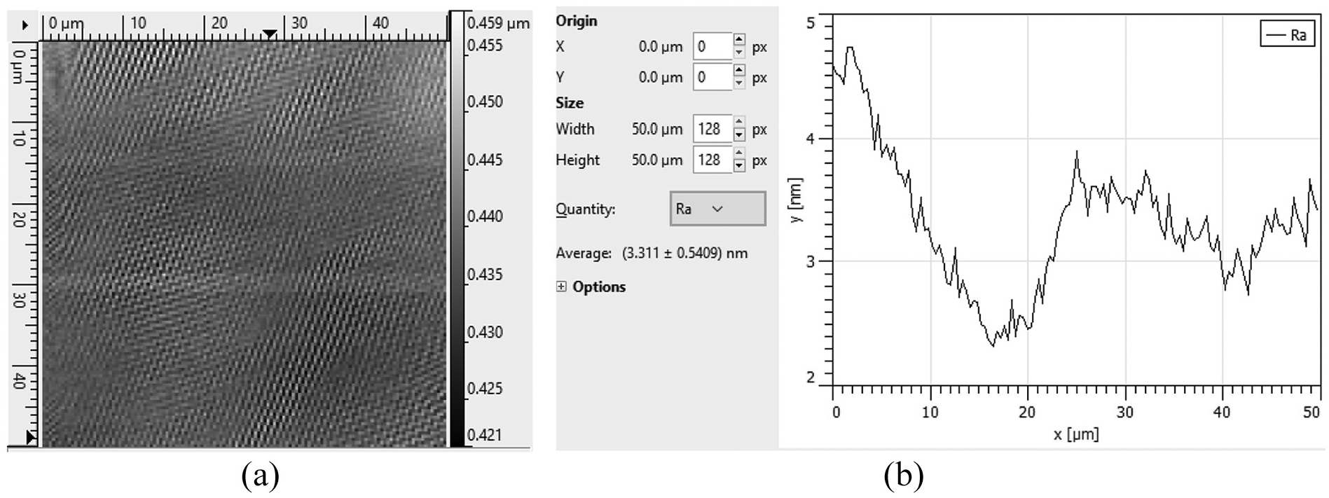
(a) AFM image of machined surface over an area of 50 µm × 50 µm and (b) Line scan from the imaged area showing the profile of a single line and average surface roughness Ra along that line (machining parameters: TiAlN-coated carbide tool, spindle speed of 7680 r/min, feed rate of 384 mm/min, and depth of cut of 0.2 mm).
Conclusion
An experimental study on the tool wear mechanisms and resulting surface finish during micro slot-milling of polycarbonate glass has been presented. The effects of machining parameters (i.e. depth of cut and feed rate) and the effectiveness of tool coatings (i.e. TiN and TiAlN coatings) on the tool wear and surface quality were investigated. The conclusions that can be drawn from this study are as follows:
The tool wear mechanism in polycarbonate machining was found to be dominated by adhesion wear, followed by chipping, plastic deformation, and catastrophic failure of the tool nose. Adhesion was the dominating tool wear mechanism in micro-milling of polycarbonate, which is probably associated with the lower glass transition temperature of polycarbonates than the tool temperature generated during machining. Instead of gradual abrasion wear, chipping of the cutting edges and plastic failure were observed more frequently, with increased occurrences at the lowest and highest settings of depth of cut.
Uncoated carbide tools were found to suffer more from adhesion wear, whereas TiAlN-coated tools were found to suffer from least amounts of adhesion wear. Both TiN and TiAlN coatings were found to be effective in minimizing adhesion wear. Although adhesion and chipping wear were reduced in coated tools, there were signs of plastic deformation and delamination of tool coatings on the coated carbide tools. However, the overall tool wear was found to be lower in the coated tools compared to uncoated tools.
In case of surface finish, the increase of feed rate resulted in rougher surface due to the increased tool marks. On the contrary, the surface finish was found to improve first and then become rougher as the depth of cut increases. The surface finish was found to depend mostly on the feed rate, with depth of cut having minimal effect. Both TiN and TiAlN coatings were found to be effective in reducing brittle fracture and the traces of the cutting tool on the surface, thus producing comparatively smoother surface finish.
Footnotes
Acknowledgements
M.J.P. and C.H. would like to acknowledge the support from the Miami University Center for Advanced Microscopy and Imaging (CAMI) for being allowed to use microscopy and materials characterization facilities.
Declaration of conflicting interests
The author(s) declared no potential conflicts of interest with respect to the research, authorship, and/or publication of this article.
Funding
The author(s) disclosed receipt of the following financial support for the research, authorship, and/or publication of this article: M.P.J. and G.K.A. gratefully acknowledge the financial support from Western Kentucky University Internal Grant RCAP 17-8057 for purchasing the materials and supplies for this study.