
Abstract
The present work focused on the investigation of hole quality characteristics in laser-drilled kenaf/high-density polyethylene (HDPE) composites. Microwave-assisted compression molding was used to fabricate kenaf/HDPE composite with 20 wt% of the kenaf fiber reinforcement. The two input parameters pertaining to the experimentation were laser power and cutting speed. Kerf taper angle, heat-affected zone (HAZ), and surface roughness were investigated to evaluate the surface quality and accuracy of the holes generated through laser drilling on composite specimens. The assessment of HAZ was performed qualitatively through image analysis on scanning electron micrographs. Additionally, the effect of composite thickness on laser drilling was also investigated for 3-, 6.7-, and 10-mm composite specimens. The central composite design was used to plan the experiments. The kenaf/HDPE composite drilled at power 120 W and speed 2 mm/s shows a minimum kerf taper angle and surface roughness of 0.056° and 3.83 ± 0.19 µm, respectively. Regression model was obtained for the establishment of relation between input variable parameters and responses. Experimental results and predicted model results exhibited good agreement with each other as they provide error less than 5.35%. The analysis of variance was carried out to obtain the significance of the model chosen for optimization of the output values, that is, surface roughness and kerf taper.
Introduction
Over the years, natural fiber polymer composites have been of growing interest and are used in various applications. Natural fiber polymer composites are extensively preferred for high-volume lightweight applications such as mechanical fastening in the automobile sector as well as manufacturing of aircraft parts. This is due to their outstanding tailored properties, fast processability, good thermal, and acoustic insulating properties. 1,2 The extensive use of these materials has strongly necessitated the need for the development of more efficient, time and cost-saving, and environmentally friendly manufacturing processes. 3 -6 Moreover, the strength of the natural fiber polymer composites depends not only on the compatibility between the polymer and the fiber but also on the fabrication process of the composites. Hence, improved mechanical properties also necessitate the investigation of an appropriate fabrication method.
Microwave-assisted compression molding (MACM) of polymer composites has emerged as a promising route for the fabrication of natural fiber-reinforced polymer composites. The MACM process involves microwave heating of the material by direct heat transfer through dielectric heating on a volumetric scale. Use of microwave energy to process a wide range of materials for various applications has been reported by several authors. 7 -19 The study reported that microwave-assisted heating of nonmetals (polymers) involves the phenomenon of dipolar and conduction loss associated with electric field effect.
To obtain near-net shape products, secondary processing in the form of machining is required on engineering components. 20,21 The machining process is also inevitable to produce holes for mechanical fastening and assembly of separately manufactured composite parts to each other or with other materials. Furthermore, the mechanical fastening efficiency majorly depends on the quality characteristics of the surface of the drilled hole. Hence, the assurance of integrity of the fasteners without compromising the strength of the composite imposes stringent demand for an efficient and effective method for quality hole production. Conventional drilling of polymer matrix composites poses several limitations such as pullout of fiber, cracking of matrix, delamination of matrix, and degradation due to frictional heat. 22 These limitations arise due to anisotropicity and inhomogeneity of the composites and these defects consequently result in countless rejected components. 23
The absence of vibrations or chatter, thrust force, and wear of tool in laser drilling provides an alternate option to conventional drilling. 22,24 However, laser drilling is a thermal process and comprises ablation of the workpiece due to laser interaction. The main challenge in the laser drilling of materials includes the minimization of thermal damage and defects produced to achieve better hole quality. Laser power and speed are the two most influential parameters affecting the surface integrity of the drilled hole. Improper selection of these parameters results in damaged drilled surface and consequently results in decreased mechanical strength. Hence, optimization of laser parameters is indispensable for achieving the desired hole quality. Previously, several investigations have been conducted to optimize the process parameters in drilling of different materials using various techniques. Li et al. investigated diode-pumped solid-state ultraviolet (UV) laser machining quality in carbon fiber-reinforced polymer (CFRP) composites of varying thickness. The study reported minimum heat-affected zone (HAZ) using a short-pulsed laser. 25 Shunmugesh and Panneerselvam performed micro-drilling on carbon fiber composites and optimized the process parameters using Taguchi and grey relational analysis. 26 Riveiro et al. investigated the CO2 laser cutting performance in the processing of 3-mm thick CFRP sheet. The study assessed the influence of process parameters in pulsed and continuous wave (CW) mode on the cut qualities such as kerf width, taper, and HAZ. 27 Choudhury and Chuan experimentally evaluated the laser cut quality of glass fiber-reinforced polymer (GFRP) composite and reported that material thickness and cutting speed positively affects the surface roughness. 28 Takahashi et al. investigated the growth mechanism of HAZ and kerf in carbon fiber-reinforced composite drilled with high power pulsed fiber laser. The study concluded the proper adjustment of scanning speed and hatching distance necessary for obtaining the desired cut quality and speed. 29 Rao et al. reported the effect of gas flow rate, cutting speed, and laser power and optimized the kerf width, HAZ, and taper percentage. 30 Solati et al. performed laser drilling on plastic-reinforced glass fiber composite and studied the consequence on HAZ, surface roughness, tensile strength, and taper angle. 31 The study concluded that optimum laser drilling parameters result in minimum surface roughness and higher tensile strength induced in laser drilling of plastic reinforced with glass fiber. Hernandez-Castaneda et al. analyzed the cutting efficiency of ytterbium fiber laser cutting of dry pine wood. 32 The study statistically established the optimum laser blind cutting parameters in single and dual gas jet conditions. Jani et al. fabricated hemp–kevlar hybrid composite with and without the addition of reinforcement with an objective to determine the machining quality of the hybrid composite through abrasive water jet (AWJ) machining. 33 The study concluded that transverse speed was the most influential factor behind kerf width, surface roughness, and material removal rate (MRR). Jagadish et al. in their study optimized the cutting parameters in AWJ machining of green composites using response surface methodology. 34 The authors employed a mathematical model to investigate the effects of pressure within the pumping system, standoff distance, and nozzle speed on surface roughness and processing time.
Conventional drilling of natural fiber-reinforced polymer composites is associated with the serious problem of fiber pullout which arises due to contact between the tool and the workpiece. Laser drilling is a noncontact process that eliminates the problem of fiber pullout. Also, the recast layer of the polymer due to laser intensity acts as a protective membrane to both the fiber and the matrix, thus eliminating fiber pullout and strengthening the outer peripheral bonding of kenaf fiber with high-density polyethylene (HDPE) matrix. Several studies have been conducted on conventional drilling as well as laser drilling of polymer composites and their optimization of process parameters was performed. Concluding the entire literature survey indicates that an ample amount of studies has been conducted on advanced machining of synthetic fiber-based composites and laser drilling of natural fiber-reinforced polymeric composites has been less investigated. Hence, the present study aims parametric optimization of CW laser drilling of kenaf/HDPE composite using central composite design (CCD) methodology. In the experimental study, laser power and cutting speed were taken as the input processing parameters and their influence on surface roughness, kerf taper, and HAZ were investigated using various techniques.
Materials and methods
Materials
Kenaf/HDPE composites were fabricated using MACM. Before the fabrication process, the kenaf fiber mat underwent treatment with a 10 wt% alkaline solution to remove the wax particles and enhance the surface roughness. 8 The fiber mats used in the experiment were of the plain weave pattern. The average diameter of the fiber and the strand was 0.5 mm and 0.02 mm, respectively. Kenaf is a naturally occurring fiber, which is economically viable, environmentally friendly and has finer sustainable and robust mechanical properties as compared to that of other organic fibers. The tensile strength of kenaf is 930 MPa which is higher as compared to that of other natural fibers such as sisal (700 MPa), hemp (690 MPa), and jute (800 MPa). 35 The HDPE is selected as a matrix in the fabrication of composite due to its versatility and appreciable physio-mechanical properties.
For the fabrication of kenaf/HDPE composite, alternate layers of kenaf fiber mat and HDPE matrix were placed into an alumina mold of size 150 × 67 × 19 mm3. The weight percentage of the kenaf fiber mat was taken as 20 wt%. The alumina mold containing stacked layers of kenaf fiber mat and HDPE was placed into a multimode industrial-grade microwave applicator (VB ceramics, Chennai, Tamil Nadu, India; Model:700 DEG °C Premium). The microwave power was at 720 W, and the processing time was 1200 s for the fabrication of the kenaf/HDPE composite. 8 During the fabrication of kenaf/HDPE composite, melting point and glass transition temperature of HDPE were primarily considered to avoid overheating of the composites. The size of the composites fabricated through MACM was 140 × 57 × 6.7 mm3.
Experimental methods
Laser drilling experiments
Holes were produced on 6.7-mm thick kenaf/HDPE composites using a computer numeric-controlled CO2 laser machining setup having laser power of 150 W (Mehta Cad Cam Systems Pvt. Ltd, Kathwada, Gujarat, India; Model: ELITA-43). Technical specifications of the laser drilling setup are mentioned in Table 1. A collimated, coherent, and monochromatic laser beam of 10.64 µm wavelength was continuously emitted by a laser source. The beam was focused using an F-theta scanning lens having an effective focal length of 50.8 mm and focusing a spot diameter of 0.25 mm on the surface of specimen. A coaxial flow of air at a pressure of 2 bar was used as assisting gas for removing the drilling residues. A standoff distance of 1.8 mm was maintained between the laser head and the workpiece. Cold water from the chiller unit cools the laser source and the laser head. The drilling operation was conducted in continuous mode where the laser source delivered a constant power.
Technical specifications of the CO2 laser system.

Holes of diameter 10 mm were drilled on a 6.7-mm thick composite specimen according to design of experiment (DoE), and their output results were recorded and analyzed (mentioned in Table 2). The diameter was selected per the specification based on industrial standards for the size of the fasteners. The schematic of the laser beam machining setup is illustrated in Figure 1. Additionally, to access the effect of thickness of the composite on the kerf taper and HAZ, laser drilling experiments were also conducted on 3- and 10-mm thick composite specimens.
Design of experiment and its corresponding output results.


Schematic of CO2 laser drilling setup.
Design of experiments
Laser drilling was performed using a computer-controlled CO2 laser to produce a hole of size 10 mm on kenaf/HDPE composites. The CCD was adopted to analyze the effect of input variable parameters (cutting speed and laser power) on the quality parameters of drilled holes (surface roughness, kerf taper angle, and HAZ). In the experimental design, two input variable parameters, laser power and cutting speed, and their three levels were considered for experimentation. Value of three different levels of input parameters, that is, laser power (P) and cutting speed (S) were 120, 127.5, and 135 W and 2, 3, and 4 mm/s, respectively. To obtain the appropriate working range of parameters, a preliminary experiment was conducted. In the preliminary experiment, drilling performed on the workpiece at the power and speed lesser than 120 W and 2 mm/s, respectively, resulted in inappropriate drilled surface of the hole due to insufficient penetration of laser beam throughout the depth of the workpiece. Similarly, an attempt to drill workpiece at the power and speed greater than 135 W and 4 mm/s, respectively, produced a cracked surface due to thermal shock generated abruptly due to high power. Hence, the higher and lower limit of the input parameters were restricted to the above-mentioned values for the investigation. Additionally, assisting gas pressure, laser frequency, hole diameter, and standoff distance were the constant parameters during the entire experimentation. The results obtained from experimentation along with their respective design are given in Table 2.
Measurement of surface roughness
Surface roughness was evaluated using surface roughness tester (Jenoptik, Jena, Germany; Model: W5) of 5 nm resolution with a stylus tip radius of 5 µm and the taper angle of 90°. For the quantification of hole surface quality, arithmetic mean deviation surface roughness was used to evaluate roughness of the surface with an assessment length of 4.8 mm and a cutoff length of 0.8 mm. An average of five measurements was recorded as the final value of surface roughness. The obtained value of surface roughness for each run is mentioned in Table 2.
Kerf taper angle measurement
Kerf taper angle (Ø) is defined as the deviation of the cut surface from the original surface and it denotes the geometrical accuracy of the finished part. In the present work, entrance and exit diameters were calculated using digital Vernier caliper (Mitutoyo, Kawasaki, Japan; Model: 500-196-30) having least count of 0.01 mm. Kerf taper angle (Ø) was calculated using the following equation: 22

where
Assessment of HAZ
The assessment of HAZ of the laser-drilled holes was done using ImageJ software tool (version: 1.8.0). Scanning electron micrographs were used for microstructural analysis and assessment of HAZ on the cross-section of the laser-drilled holes. The HAZ was investigated for analyzing the extent of damage incurred during laser drilling. The HAZ was qualified by the microstructural changes that occurred due to the incursion of the laser beam into the composite specimen.
Regression modeling for hole geometrical features
The responses were recorded and analyzed into the Design-Expert 10 software (Trial version, V10) (according to DoE Table 2). For each response, the regression equation/model was developed, followed by statistical testing for ensuring the adequacy of the prediction of responses. It was preceded by five confirmation experiments to validate the model with the best possible combination of laser input parameters. Statistical analysis (sum of squares of the errors, standard error of estimate, F statistics, and p value) for different parameters such as surface roughness and kerf taper angle of the laser-drilled kenaf/HDPE composite was carried out. To confirm the significant laser input variable parameters responsible for affecting the surface integrity of the drilled holes, the analysis of variance (ANOVA) test was accomplished on each of the experimental responses. The interpretation of the results of statistical analysis is discussed in detail.
Results and discussion
Analysis of machined surface
Laser drilling mechanism
Figure 2 shows the typical CO2 laser drilling and ablation mechanism through various stages. Stage I represents the schematic of the front view of kenaf/HDPE composite fabricated through MACM. In stage II, high-power laser beam in continuous mode was irradiated on the composite surface. Stage III depicts the penetration of the laser into the composite. The drilling of the composite takes place due to laser ablation. Laser ablation is the ionization mechanism wherein the ablation of mass from the solid surface takes place in the presence of intense laser beam irradiated on the surface. The molecules of the composite were desorbed and ionized with the help of laser pulse resulting in the formation of melting zone containing molten material. This molten material can further be removed from the machining zone by compressed air at 2 bars. Stages III, IV, and V depict heat transfer during laser drilling and formation of HAZ. Progressive stages of laser drilling in the kenaf/HDPE composites are shown through stages III to VI in Figure 2. The immediate effect of laser beam on composite can be seen in the form of the melting of HDPE matrix and the burning of kenaf fiber (Figure 2). It is interesting to note that during laser drilling, kenaf fibers were burnt at the vicinity of the periphery of the hole generated and the molten HDPE matrix was recasted on the drilled surface of the hole.

Schematic of CO2 laser drilling and ablation mechanism.
Kerf taper angle
ANOVA table for taper angle.
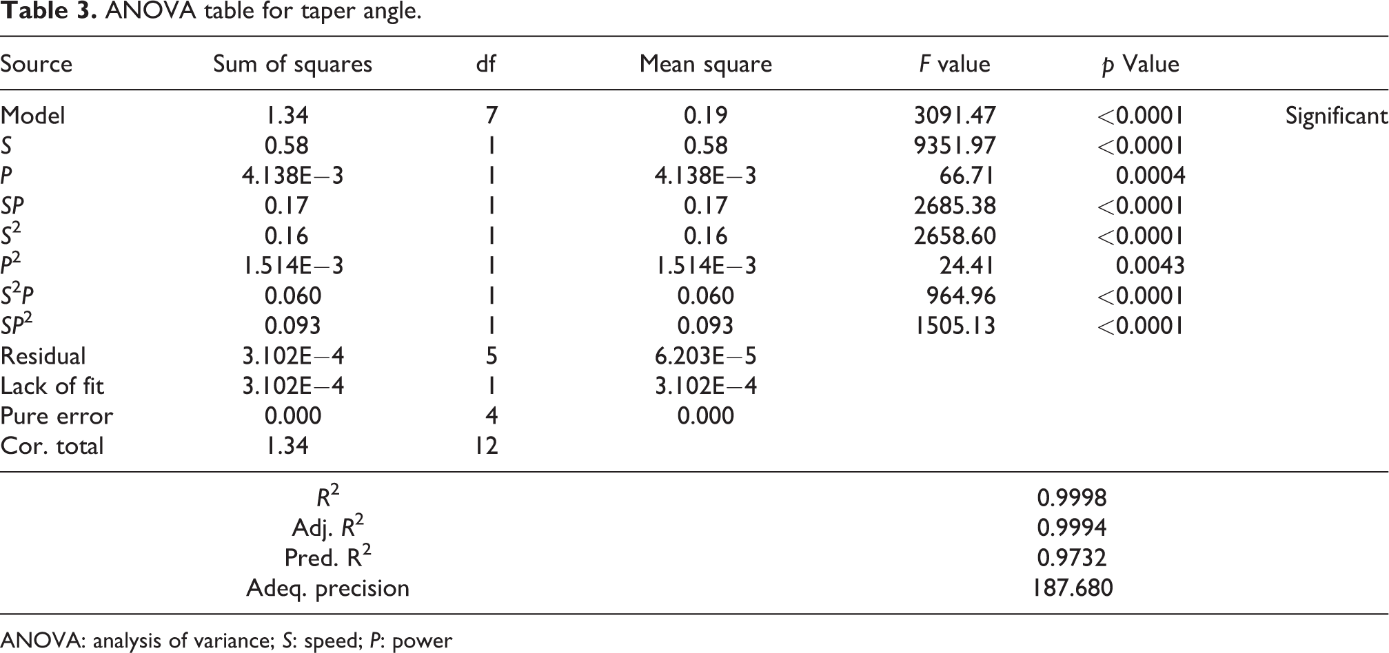
ANOVA: analysis of variance; S: speed; P: power

From the ANOVA (Table 3), it was observed that cutting speed and laser power are the two input parameters that significantly influence the taper angle. Figure 3 exhibits the predicted versus actual plots and combined effect plot. The predicted versus actual plot as shown in Figure 3(a) demonstrates that the predicted values and actual values are approaching each other. Figure 3(b) exhibits the combined effect of speed and power on the kerf taper angle. From the plots, it was observed that the kerf taper angle showed inverse proportionality with the cutting speed and direct proportionality with the laser power. As the cutting speed increases, the interaction time between the laser and the composite specimen decreases. Hence, the depletion of the material at the upper surface of composite specimen was minimum. Further penetration of laser beam through the entire material thickness leads to the diffusing of heat in different directions resulting in reduced energy intensity and consequently narrow kerf width at the bottom surface due to which taper angle decreases. 22,31,36 Increasing laser power leads to the absorption of more thermal energy emitted from the laser beam incident on the surface of the workpiece. As a result, excessive evaporation of material occurs from the top surface of the workpiece and because of the notable difference in kerf width at the top and bottom surface, kerf taper angle increases. Rao et al. reported similar dependence of kerf taper on laser power and cutting speed in fiber laser cutting of CFRP composites. 30 However, the result is contrary to the trend reported by Bharatish et al., wherein they observed a decrease in kerf taper as laser power increased during pulsed mode CO2 laser drilling of alumina ceramics. This was due to the increment in exit diameter with increased laser power. 37 The contrasting results might be due to the different operating conditions in respect of both types of material and mode of drilling.

(a) Predicted versus actual plots for kerf taper angle. (b) Combined effect plots for speed and power versus kerf taper angle.
Surface roughness
The quadratic model was selected for the analysis. The ANOVA table for the regression equation for the surface roughness with F values, p values, and other parameters of adequacy measures are mentioned in Table 4. For this model, F value = 42.16 and p value < 0.05 confirm significance of the developed regression equation. Therefore, the obtained regression equation may be used to predict the value of the responses. The significant model terms are S, P, SP, S 2, and P 2 . The regression relation in the coded form for the prediction of output is given in the following equation:
ANOVA table for surface roughness.

ANOVA: analysis of variance; S: speed; P: power

Figure 4 represents the graphical regression along with the response surface plot depicting the effect of laser power and cutting speed on surface roughness. Figure 4(a) signifies that the actual and predicted values of surface roughness are approaching each other. The combined interaction of cutting speed and laser power on the surface roughness can be studied from Figure 4(b). From Figure 4(b), it is evident that surface roughness reduces with an increase in cutting speed, whereas it increases with power. The result is corroborated with the observations of Choudhury and Chuan in their experimental investigation on laser cut quality of GFRP composites. 28 Less exposure time of the composite specimen with laser energy at increased speed results in lower surface roughness. On increasing power, laser intensity on the surface of the workpiece increases which leads to the absorption of more thermal energy emitted from the incident laser beam. This process results in excessive degradation of the material, thereby contributing to the increase in surface roughness. 30

(a) Predicted versus actual plots for surface roughness. (b) Combined effect plots for speed and power versus surface roughness.
Heat-affected zone
Figure 5 illustrates the scanning electron microscope cross-sectional images of the thermally damaged area such as HAZ, cracks produced in three composite samples, that is, C4, C5, and C8. Laser power and cutting speed are the critical parameters affecting the HAZ. From Figure 5(a), it is observed that there is a smoothly textured zone in a laser-processed region along with reduced HAZ of width 0.52 mm with extreme cutting speed (4 mm/s) and minimum laser power (120 W). Whereas from Figure 5(c), it is observed that there is a significantly larger HAZ of width 0.8 mm with minimum cutting speed (2 mm/s) and maximum laser power (135 W). Recast layer of comparable thickness is visible in Figure 5(c). This is due to high laser power and low cutting speed. Thus, HAZ varies inversely with the interaction time or laser cutting speed. The HAZ increased with laser power. Figure 5(b) shows the intermediate HAZ of width 0.65 mm in the specimen C5 drilled at speed 3 mm/s and laser power 127.5 W. Li et al. observed a similar trend in HAZ variation and reported narrow HAZ with an increase in speed during UV laser cutting of CFRP composites. 25 The study finally suggested the use of pulsed mode and fast scanning speed to machine CFRP composites. Rao et al. also observed an increase in HAZ with an increase in speed. 20,30,35

SEM micrographs of HAZ for specimen: (a) C4, (b) C5, and (c) C8.
Optimization of responses
During optimization, the aim was to find out the optimal variables, which were responsible for both (kerf taper angle and surface roughness). Maximization of desired variable and minimization of the undesired variable were under consideration during optimization. The criteria of desirability for optimization are presented in Table 5. The solution obtained is expressed in desirability ramp plots in Figure 6. The desirability of the model obtained in this research work is 83.1%. The optimized values of cutting speed and power were 4 mm/s and 122.593 W, respectively.

(a to d) Desirability ramp plots.
Criteria of desirability for optimization.

Effect of material thickness
Before embarking on assessing the influence of laser input processing conditions on kerf taper variation, an investigation on the general nature of hole formation during laser drilling was performed. For this purpose, laser drilling was performed on 3-, 6.7-, and 10-mm thick composite samples. The variation of kerf taper angle for each thickness was investigated under identical laser drilling conditions with 127.5 W laser power and 3 mm/s speed. Figure 7 shows the kerf taper angle values calculated for each thickness of the samples investigated using equation (1) of kerf taper angle. For the 3 mm thickness of the composite sample, the taper angle was calculated to attain a maximum value of 0.75°, while the kerf taper angle for a 6.7-mm thick sample was calculated to be 0.68° which is 9.33% lesser as compared to that of 3-mm thick sample. The kerf taper angle significantly decreased with increased sample thickness because the diameter at the exit reduces on increasing the thickness of the sample. Hence the kerf taper angle of the hole drilled on a 6.7 mm sample was relatively smaller as compared to that calculated in 3-mm thick sample. It has been observed by other authors in their work that the amount of molten material ejection during laser drilling increases in proportion to the diameter to depth ratio of the sample. Hence drilling of relatively shallow holes in thinner material results in a large angle of liquid material ejection which leads to a relatively higher kerf taper angle. 38,39 However, on increasing the thickness of the sample further up to 10 mm, the kerf taper angle significantly increased to a value of 0.71° which was 4.41% higher as compared to that in 6.7 mm thickness of the sample. This is because of the necessity of increased laser power (from 127.5 W to 135 W) to generate a hole in thick composite samples. In addition to the kerf taper angle, HAZ is one of the defects that are inherently associated with laser drilling. During the present study, it was observed that increasing material thickness showed a reduction in the extent of HAZ. As shown in Figure 7, the width of HAZ was observed to be maximum for a 3-mm thick material (0.69 mm). Increasing the thickness beyond 3 mm showed reduction in the width of HAZ by 5.79% and 10.14% and attaining values of 0.65 and 0.62 mm for 6.7 and 10 mm composites, respectively. Although a 10-mm thick composite sample showed 4.61% reduction in the extent of HAZ relative to that in a 6.7-mm thick composite. But increasing thickness up to 10 mm leads to an increase in taper angle as discussed previously. Hence, the optimum thickness entailing minimum kerf taper angle with a little extent of HAZ was preferred to be 6.7 mm for carrying out the further investigation.

Effect of material thickness on kerf taper angle and HAZ.
Conclusions
The present experimental study involved analyzing the effects of laser power and cutting speed on the quality of holes on kenaf/HDPE composite using the CCD technique. The results support the following conclusions: CO2 laser is capable of drilling kenaf/HDPE MACMed composite. Optimum laser drilling parameters can yield improved quality of the drilled holes. Laser power and cutting speed are influential parameters on kerf taper angle, surface roughness, and HAZ in laser-drilled kenaf/HDPE composites. The thickness of the composite workpiece has a significant effect on kerf taper angle and width of the HAZ.
Increasing the workpiece thickness from 3 mm to 6.7 mm showed a reduction in kerf taper angle by 9.33%. However, the same trend was not observed on increasing the material thickness up to 10 mm.
Increasing the workpiece thickness from 3 mm to 6.7 mm showed a 5.79% reduction in the width of HAZ. Additionally, a 4.61% reduction in the width of HAZ was observed on further increasing the thickness of workpiece up to 10 mm. Kerf taper angle decreased by 12% with an increase in speed by 33.33%, while it was increased by 9.6% as the laser power increased by 11.1%. Surface roughness varies inversely with cutting speed while it has a direct correlation with laser power.
Laser beam at 135 W cutting at 2 mm/s resulted in the highest HAZ of 0.80 mm width. The percentage increase in width of HAZ with variation in power (120 W) and speed (4 mm/s) is calculated to be 53.84%, which signifies that HAZ is considerably dependent on laser power and cutting speed. Desirability of 83.1% was obtained at optimized parameters (power = 122.593 W (rounded to 123 W) and cutting speed = 4 mm/s).
Validation of optimized parameters was done by experimentation and reveals a relative error of 2.3% and 5.35% for surface roughness and kerf taper angle, respectively.
Footnotes
Acknowledgements
The authors, Renu and Manoj are grateful to MHRD, Government of India, for financial support during the work.
Declaration of conflicting interests
The author(s) declared no potential conflicts of interest with respect to the research, authorship, and/or publication of this article.
Funding
The author(s) received no financial support for the research, authorship, and/or publication of this article.