
Abstract
This paper presents an investigation of the drilling performance of glass fiber reinforced polymer (GFRP) composite based on the thrust force, temperature, and delamination factor (at entry and exit of the hole). High-speed steel (HSS), solid carbide (SC), and solid carbide Balinit® Helica coated (SCBH) twist tools were used for the drilling process. Other drilling parameters were high spindle speeds (12,000, 15,000, and 18,000 rpm), feed rate (300, 500, and 700 mm/min), and laminate thickness (3, 5, and 7 mm). ANOVA and response surface methodology were developed to examine the drilling process based on input and output parameters. Results showed that delamination was observed in the form of matrix debonding, uncut fibers, and fiber pull-out. The best drilling performance was achieved by the SC and SCBH tool at a low feed rate (300 rpm) and high speed (18,000 rpm), and high laminate thickness (7 mm).
Introduction
Glass fiber-reinforced polymer (GFRP) composites are prevalent in engineering applications because of their low cost and excellent properties compared to metals.1,2 Therefore, they are commonly used in aerospace and marine industries. 3 For proper drilling operation, the composite parts must be joined during the final assembly, and around 70% of the machining processes involved drilling. Despite the development of various non-conventional drilling techniques, for instance, laser machining, water-jet machining, electrochemical, electro discharge, and electrochemical discharge to make the holes of composites, conventional mechanical drilling methods (such as milling, CNC drilling, and mechanical drilling) are still used as primary applications for fiber-reinforced polymer composites (FRPCs) due to financial benefits. Delamination is the main issue in FRPCs, which occurs due to the abrasive, hard, heterogeneous, and anisotropic fiber structure. Delamination influences the dimensional accuracy and surface finish of the hole, which causes the rejection of composite parts during the assembly stage. 4 There are many vital problems in FRPCs regarding drilling, such as fiber frying, spalling, chipping, fuzzing, fiber/matrix debonding, resin loss, uncut fiber, and fiber breaking compared to conventional materials. 5 Delamination influences the dimension accuracy and surface finishing of the hole, which causes the 60% parts rejection at the assembly stage. 6 The thrust force is a critical reason for delamination in GFRP composites. 7 Therefore, the thrust force must be kept low for a high-quality drilled hole. The lower thrust force could be found at a low feed rate and spindle speed. 8 Another crucial factor is the drilling-generated temperature that affects critical thrust force. 9 Feed rate and cutting speed have a crucial impact on delamination and thrust force. 10 Lower delamination (at entry and exit hole) in the GFRP composite could be achieved by drilling at a low feed rate and speed. 11 Hence, the optimization of these process parameters is required for good drilling performance. High-speed drilling is an effective method to decline the drilling induce damage around the hole.12,13 Tool diameter also plays a critical role in delamination. 14
An investigation on the impact of various glass fiber/graphene/epoxy composite thicknesses on drilling performance was studied. 15 It was reported that lower thickness (2 mm) of composite had excellent performance for high-speed steel (HSS) drill at higher speed and lower feed rate. The effect of various drilling parameters such as feed rate and speed on delamination and tool wear for 6 mm thick of GFRP composite was examined. 16 It was found that the optimized condition was 951 rpm (speed) and 1 mm/min (feed rate) for the lowest delamination and tool wear. Another study on the drilling properties of 4 mm thick GFRP composite using various drill bits such as HSS, solid carbide, and tipped carbide. 17 It was reported that the HSS tool showed highest thrust force than other tools despite showing a higher delamination factor (DF). The temperature during the drilling operation of the GFRP composite having 8 mm thickness was examined and found that the feed rate has a greater influence on temperature than speed, and it rises with the feed rate at a higher speed. 18 The different laminate thicknesses (3, 6, 9, and 12 mm) of GFRPs using a carbide coated drill were investigated. 19 They reported that delamination augmented when the feed rate increased. However, a higher feed rate (150 mm/min) showed the opposite response. The thrust force with critical feed for GFRP composite drilling using a backup plate was also studied. 20 Tool angle and speed had a crucial impact on thrust force during drilling of GFRP composite. 21 The thrust force was higher (100 N-190 N) at low speed (600–1800 rpm) and a higher feed rate during GFRP composite drilling. 22 The heat and delamination during GFRP composite drilling were examined and found that high temperature was generated at a low feed rate for the HSS twist drill bit. 23 The poor drilling performance of carbon/nanocarbon/furfuryl resin hybrid composite using the Balinit® Helica coated carbide drill was also presented. 24 The thrust force, drilling temperature, and delamination of 20 mm thick of GFRP composite during the drilling operation were studied. 25 It was found that the temperature and thrust force were significantly influenced by speed and feed rate, respectively. Twist drill has better drilling performance than the candlestick tool in terms of lowering the thrust force, push-down, and peel-up delamination for GFRP composite. 26
Although Balinit® Helica coated drill bit has been widely used in machining of the hard material such as alloy and metal compounds, there is no study in GFRP composite drilling using this tool, especially at a higher spindle speed. Moreover, most published studies focus on thrust force; they did not focus on the impact of generated temperature, which is inherent while performing the drilling. This paper is aimed to improve and analyze the drilling performance of GFRP composites. The main input variables are tool materials, speed, feed rate, and thickness. The drilling properties are measured based on output responses such as thrust force, temperature, DF at the entrance, and drilled hole exit. Analysis of variance (ANOVA) and response surface molding (RSM) is applied to process the drilling variables.
Materials and methodology
Materials and fabrication
E-glass was purchased from Castmech Technologies Sdn Bhd, Ipoh, Malaysia. It has a fiber diameter of 24 µm, 380 ± 40 g/m2 of mass per unit area, 750 yarns per meter with 1.2 kg/m linear density, and fiber density of 2550 kg/m3. Epicote 2820 was supplied by Wee Tee Tong Chemical Sdn. Bhd, Johore, Malaysia, and used as a matrix in the fabrication process. Epicote 2820 consists of two parts: part A, the epoxy, and part B, the hardener. The vacuum infusion molding (VIM) technique was used to fabricate the composites.
23
The E-glass and VIM fabrication process is given in Figure 1(a) and (b), respectively. Three GFRP plates were fabricated for each of three different thicknesses with a dimension of 35 cm x 35 cm and thickness of 3 mm, 5 mm, and 7 mm, respectively. The stacked of fiber clothes used in this study were 5 plies of woven glass fiber to produce 3 mm thick composite laminate test samples, 8 plies of woven glass fiber for the 5 mm thick composite laminate test samples, and 11 plies of woven glass fiber were used for the 7 mm thick composite laminate. It was ensured that the vacuum pressure used in the manufacturing process was set to 90 kPa and a motor power of 0.37 kW. The fabrication of the composites was done at room temperature. The impregnation process lasted 10, 12, and 15 min for the 3, 5, and 7 mm thick GFRP composites, respectively. Post-curing of the composites was done for 2 h at 90°C in the oven. a) Twill woven glass fiber, b) VIM set up, and c) Carbolite CWF1300 used in resin burn off test.
The composites' fiber volume fraction (FVF) was measured using the ASTM D 2584 burn-off test. The Carbolite Furnace CWF1300, which has a maximum working temperature of 1300°C, was used (Figure 1(c)). The specimens were heated in the furnace for around 30 min at around 550°C. For 30 min, the specimen burned evenly and moderately until the fiber remained and the burning stopped. The efficiency of this setup was checked by infusing without epoxy matrix to obtain the defect-free composite.
Equation (1) was used to calculate the FVF.
27
Where V, ρ, and W are FVF, density, and weight fractions of the specimen, respectively. Subscripts f, m, and p are fiber, matrix, and void contents.

The fiber volume fraction of the fabricated GFRP composite.

Drilling method
The drilling process was performed using the CNC milling machine, Mazak Variaxis 630, whose power and maximum speeds were 30 kW and 25,000 rpm, respectively. The drilling was carried out in dry condition. Three types of twist drill tools of 6 mm diameter, which are high-speed steel (HSS), solid carbide (SC), and solid carbide Balinit® Helica coated (SCBH), were selected to drill the hole in GFRP composite. All the physical properties of drill bits are the same such as 0.63 mm web thickness, 25 mm flute length, 118° point angle, 25° helix angle, and 143° chisel edge angle. However, the thermal conductivity (21, 84, and 75 W/m.K) of HSS, SC, and SCBH and the thermal expansion coefficient (9.7 × 10⁻⁶ K−1 and 5.5 × 10⁻⁶ K−1) of HSS and SC drill bits were different due to material differences respectively. HSS tool is used for composite drilling because of low cost and easy availability, whereas solid carbide coated, and uncoated twist drill bits are more common in mass production at high speed.
Drilling process parameters and their levels.

Drilling process parameters such as spindle speed (12,000, 15,000, and 18,000 rpm), feed rate (300, 500, and 700 mm/min), and composite laminate thicknesses (3, 5, and 7 mm) were chosen based on published studies that found the most critical factors influencing the surface integrity of drilled holes on delamination, temperature, and thrust force during drilling.10,19,21,33–40 These studies reported that faster material removal rates reduce the thrust force because of higher spindle speed. When employing a faster spindle speed, the heat generated during drilling has been indicated as a factor contributing to composite delamination; however, research on the heat generated during drilling is still restricted. When high-speed machining has been quickly adopted in various industries, it is critical to understand drilling-generated temperature in composite drilling. The feed rate has the most significant impact on the thrust force, which in turn has an impact on the delamination factor. For good quality of drilled hole, the increased downward force produced by using a higher feed rate must be adequately selected.19,35,36,41–46 The feed rate is the most crucial delamination factor, followed by material thickness and drill bit diameter.19,47–49 For each test case, an average of 10 holes were used to examine the drilling properties of the composites.
Measurement of drilling parameters
During drilling of GFRP composites, the thrust force was measured by a dynamometer (Kistler). As demonstrated in Figure 2(a), the dynamometer was equipped with three piezoelectric sensors covering the x, y, and z-axis. These sensors detect minute changes in force generated during the drilling experiment to a sensitivity of ±0.5 N. The signals detected by the sensors were then transmitted to the Kistler 9017b multichannel charge amplifier to be amplified and converted into a proportional voltage. These amplified voltages were then translated into thrust force versus time graph with a Dynoware equipped computer. a) Thrust force measurement setup, b) temperature measurement setup, and c) DF measurement.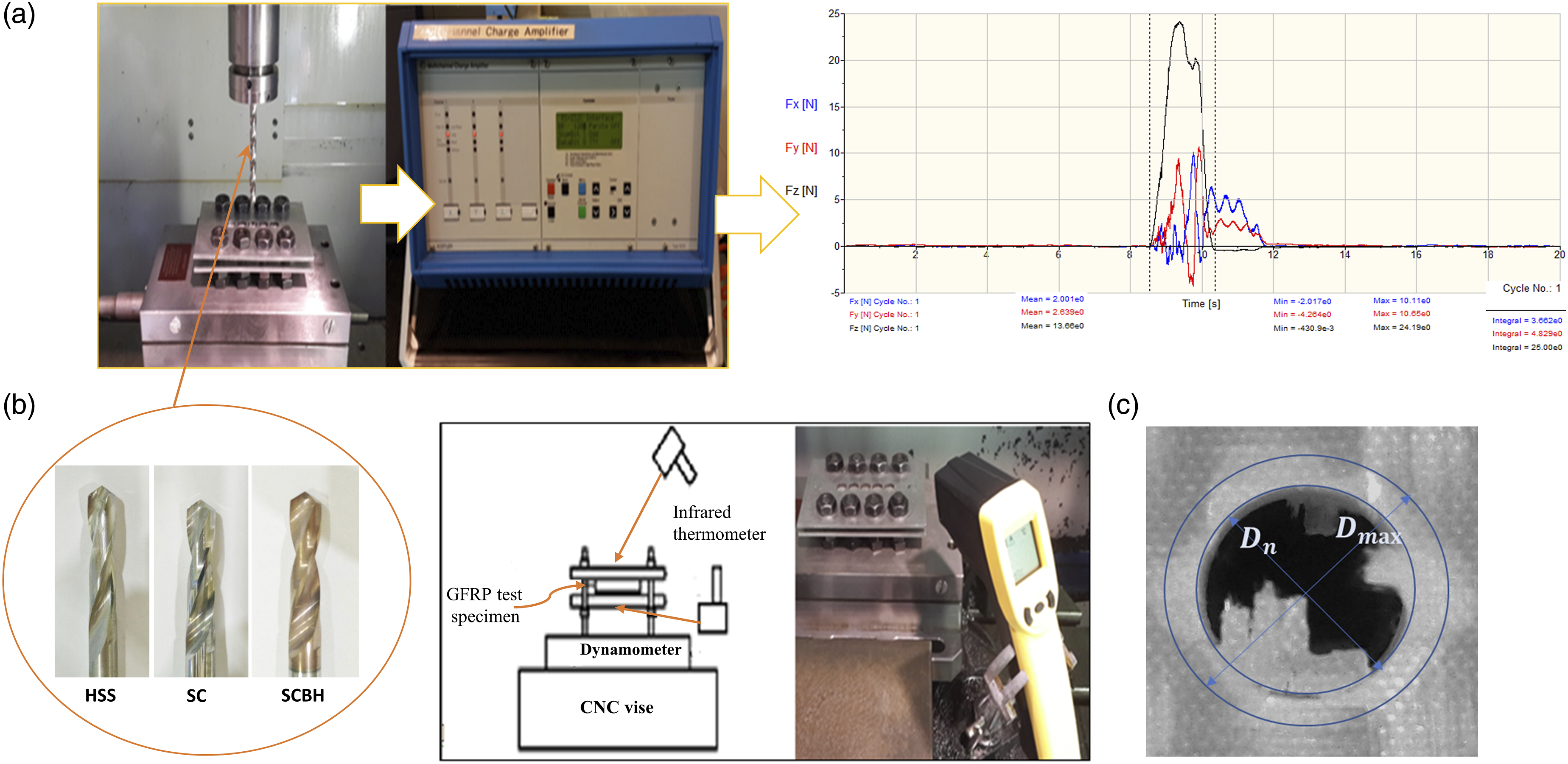
Two infrared thermometers (Edison EDI-312-4000K) were utilized to measure the drilling temperature; they placed 300 mm from the drill entering and exiting the GFRP composite test sample (as shown in Figure 2(b)). The temperature ranged between – 20°C to 537°C, at a response time of 0.5 s.
The DF is one of the vital variables used to examine the drilled hole quality. The specimens were investigated using a Mitutoyo 3D non-contact measuring system and QVPAK software to ensure no defects before the drilling process. The specimen with drilled holes was examined to capture images with four times magnification. The delaminated area is bulged because of damage that occurs near the drilled hole. The damaged part appears thick, and it creates differences in distance from the lens of the 3D non-contact measuring system to the drilled hole surface. The drilled hole’s delaminated area is easier to detect by inverted using image processing software. Finally, the delaminated hole diameter is calculated using CAD software. As illustrated in Figure 2(c), DF was calculated by using equation (2),
39
where 
The design of experiments with RSM was conducted to examine the relationship between drilling input and output variables. ANOVA using the general linear model was run to analyze the most statistical parameters which impact the drilling performance (thrust force, temperature, and DF) of GFRP composites. The analysis was done to a significance level is 5% (confidence level of 95%). Finally, the optimized condition was determined based on tested parameters for GFRP composites. The Minitab 17 software was used to run the RSM.
Results and discussion
Experiment results
Experimental conditions for drilling and the results for thrust force, temperature, and DF.
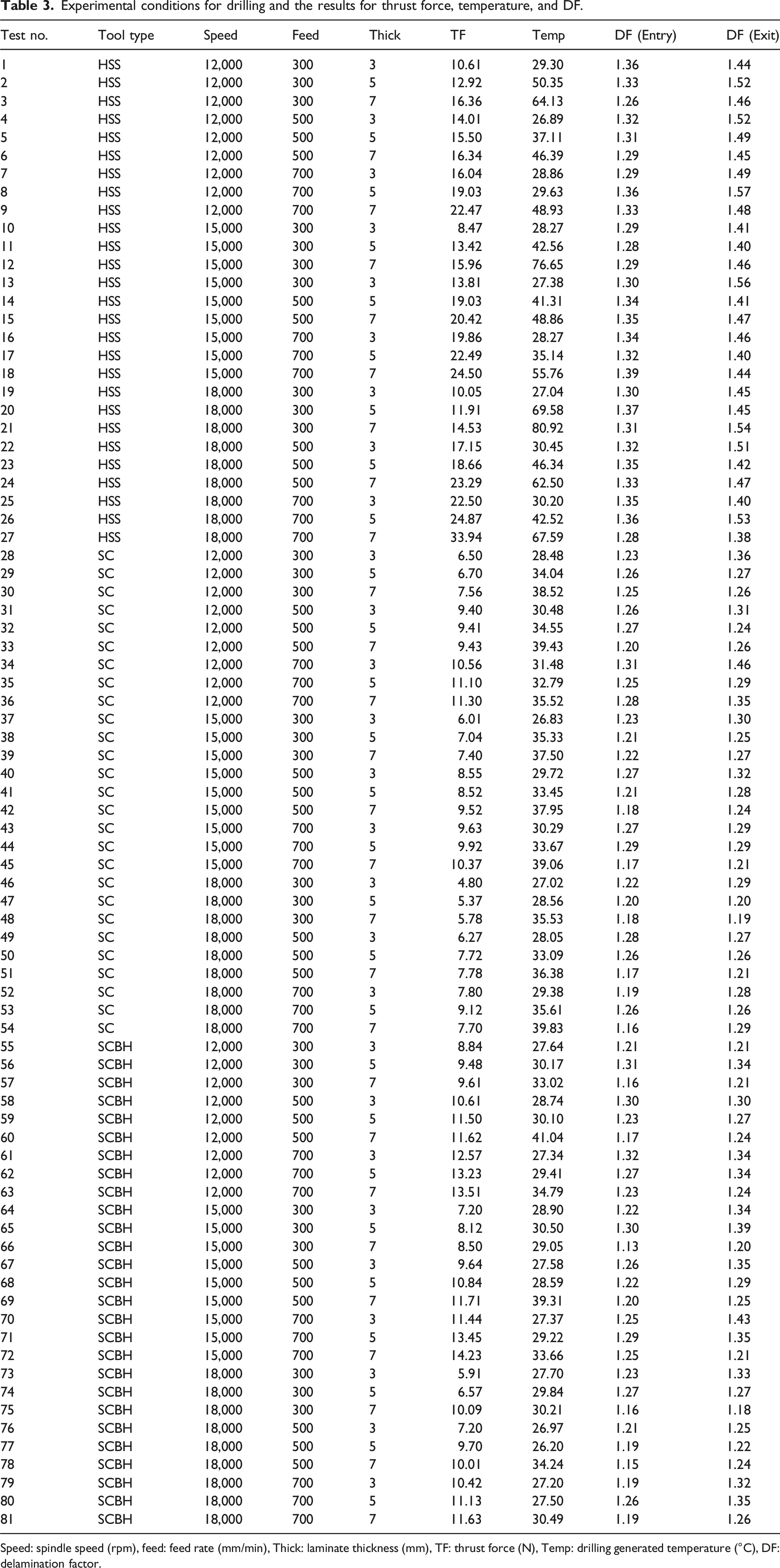
Speed: spindle speed (rpm), feed: feed rate (mm/min), Thick: laminate thickness (mm), TF: thrust force (N), Temp: drilling generated temperature (°C), DF: delamination factor.
Based on Table 3, the lowest DF value was obtained for test 66 with 15,000 rpm, 300 mm/min, and 7 mm for the SCBH tool, which the DF quality compared with HSS and SC drilling tools in the same conditions as given in Figure 3. 3D Non-contact images of typical delamination of 7 mm thick GFRP laminate at 15,000 rpm spindle speed and 300 mm composite’s thickness.
The hole quality can be analyzed based on medium and higher speed. In the case of medium speed (15,000 rpm), hole quality was examined at 300 mm/min feed rate and 7 mm composite’s thickness (for HSS test 12, SC test 39 and SCBH test 66 in Table 3). As described in Figure 3, the SCBH tool proposed better hole surface quality than SC and HSS. The primary types of delamination were formed in fiber pull-out, un-cut fibers, and matrix debonding. The HSS tool caused the highest drilling generated temperature and thrust force and highest delamination defects on a drilled hole in GFRP composites comparing SC and SCBH tools (Figure 3(a)) at the same drilling condition. The SCBH displayed only slight fiber pull-out and matrix debonding, and almost no uncut fibers were seen inside the hole after drilling at the same drilling condition (Figure 3(c)). Hence, this tool can be the best choice for better performance in terms of hole quality at 15,000 rpm drilling speed. For considering the higher drilling speed, the SC tool showed the high quality of drill hole at higher speed (18,000 rpm), lower feed rate (300 mm/min) and higher composite’s thickness (7 mm) compared to HSS and SCBH (Figure 4). SC had the lowest thrust force (5.8 N), while HSS and SCBH had 14.5 N and 10.1 N at the same condition. The SC displayed only slight fiber pull-out and matrix debonding, and almost no uncut fibers were seen inside the hole after drilling (Figure 4(b)). Hence, the SC drill bit can be the best choice for better performance at a higher speed in terms of excellent hole quality and lower thrust force. Lower thrust force is crucial for long tool life.
50
3D Non-contact images of typical 7 mm thick GFRP laminate delamination at 18,000 rpm spindle speed and 300 mm/min feed rate.
ANOVA analysis
ANOVA analysis for the thrust force, temperature, DF at entry and exit.

T: tool types; s: speed; f: feed rate; t: thickness; Seq SS: Sequential sums of squares; * interaction between the parameters.
The thrust force was significantly influenced by feed rate, thickness, and tool type. Insignificant factors are eliminated when the p-value was higher than 0.05. There was no crucial contribution of speed found on thrust force. However, the second-order interaction with tool type (tool type and speed, tool type and feed rate, tool type, and thickness) and the third-order interaction (tool type, speed, and feed) showed the essential impact on thrust force.
Regarding the drilling generated temperature results, it can be concluded that its drilling response is statistically influenced by tool type, feed rate, and laminate thickness (as given in Table 4). Other parameters did not display a crucial impact on the temperature. Those parameters showed a significant contribution in second-order interaction with tool type (tool type and speed; tool type and feed rate; tool type and thickness; feed rate and thickness) and the third-order interaction (tool type, feed rate, and thickness).
As shown in Table 4, both delamination factors (entry and exit) were affected by all main drilling parameters. The tool types showed the highest significance, followed by thickness. There was no significant impact on the interaction between the parameters on DF (entry); however, second-order interaction (tool type and speed; tool type and thickness) and third-order interaction (Tool type, speed and feed rate; tool type, feed rate, and thickness) showed a significant effect of DF (exit). The main reason for the effect of tool type and speed on DF is explained later on considering the effect of chip residual on drilling performance.
Based on all the significant drilling parameters presented in Table 4, the thrust force can be controlled by the tool type, feed rate, and thickness. The drilling generated temperature can be reduced by careful selection of tool type and thickness of laminates. Low delamination in the holes' entrance and exit can be reduced by optimum selection of all major factors.
RSM analysis of drilling performance parameters
The graph in Figure 5 displays an interaction plot matrix for the mean of thrust force, which shows no interaction (parallel lines) for speed * feed, speed * thick, and feed * thick, but other combinations presented the interaction. The feed rate was a more significant variable compared to speed and thickness for thrust force. The speed * feed graph that all drilling tools showed slightly different trends in which SC and SCBH showed the lower thrust force at high speed compared to HSS tools. Interaction graph for thrust force.
For the HSS tool, thrust force increased with speed, feed rate, and thickness (Figure 6(a)–(c). SC and SCBH tools offered almost similar thrust force responses for feed rate and thickness; however, the effect of speed rate was contrary for the HSS tool (Figure 6(d)–(i)). The thrust force was found to increase with a rise in feed rate. However, it decreased when the drilling speed increased for SC and SCBH tools (Figure 6(d)–(i)). The composite thickness had a negligible impact on thrust force for SC and SCBH tools at low spindle speed but insignificant at the higher speed. Surface plot of TF versus feed and speed, a), b), and c) for HSS tools, d), e) and f) for SC tools, and g), h), and i) for SCBH tool with varying thickness.
Moreover, drilling at a higher speed showed benefits in these tools compared to the HSS tool for lowering the thrust force (Figure 5). HSS has the increasing trend for trust force while drilling speed increases due to exceeding the optimum drilling conditions for GRFP composites; therefore, the thrust force is increasing contrary to SC and SCBH drill. Considering that all the other parameters are the same for drill bits, the hardness of the drill bit or its coating materials is the most crucial parameter.
It has been observed that the thrust force of HSS drills is higher when compared with SC and SCBH drills because HSS drills are less hard and wear out more effectively. 17 The GFRP composite chip residual on the HSS twist drill bit was detected, while there was almost no chip residual on the SC. The GFRP composite residual not only increases the frictional force between the tool bit and cutting zone by its abrasive nature, but it may also cause rapid tool wear on HSS, which is one of the reasons for higher thrust force for high-speed drilling of GFRPs using HSS tool.51,52 The high tool wear reduced the edge sharpness of the tool bit and generated higher thrust force from the uncut thickness of the GFRP laminates.51,52 Therefore, the GFRP composites' thickness significantly influenced the thrust force, and the thicker composite generated higher thrust force, thus increasing the delamination supported by Table 3 and Figure 6. The lower thrust force generated from SC and SCBH tools than the HSS tool may be due to higher speed, where the high material removal rate compensated the downward thrust force at a higher feed rate. Tool wear of the HSS drill bit is main factor that causes the thrust force to increase, where SC and SCBH drill bit has the advantage of higher material hardness, thus making them less prone to tool wear and retained edge sharpness more effectively. 53 SCBH tool showed a slightly higher thrust force than SC tools (Table 3) due to the Balinit® Helica coating. It may be due to higher residue produced by SCBH, as higher residue causes higher frictional force, resulting in ameliorate thrust force. 54 Since glass fiber reinforcement is an abrasive and hard material, Balinit Helica had to be used due to the coating’s AlCrN based properties that offer better abrasion resistance, lower adhesion tendency, and lower friction. 55 This coating and most of the coatings (TiAlN, TiN and diamond) are ceramic, making it vulnerable to mechanical impacts caused by intermittent cuts of the fibers. 56 Abrasion can cause wear on the edges. 57 However, Balinit Helica coating is more resistant to abrasion, and drilling still damages it despite its abrasion resistance.54,56
Figure 7 displays the interaction graph for drilling generated temperature. For HSS, the temperature was found to increase with the rise of speed and thickness which can be seen from tool-type * speed and tool type * thick interaction graphs. However, the feed displayed an opposite response to the temperature. The temperature was almost constant, although a small decrement was observed when speed increased for SC and SCBH tools. The temperature is often related to a high feed rate that develops high thrust force during drilling, which increases the frictional force between the cutting tool and the cutting material. However, with a high feed rate, the cutting time may be reduced with a faster traveling time. The tool type and thickness were other vital factors that displayed a crucial impact on the temperature. The temperature displayed an increasing trend with augmentation of the laminate thickness for all tested tools. Other combinations of interactions did not show any signs. Interaction graph for drilling generated temperature.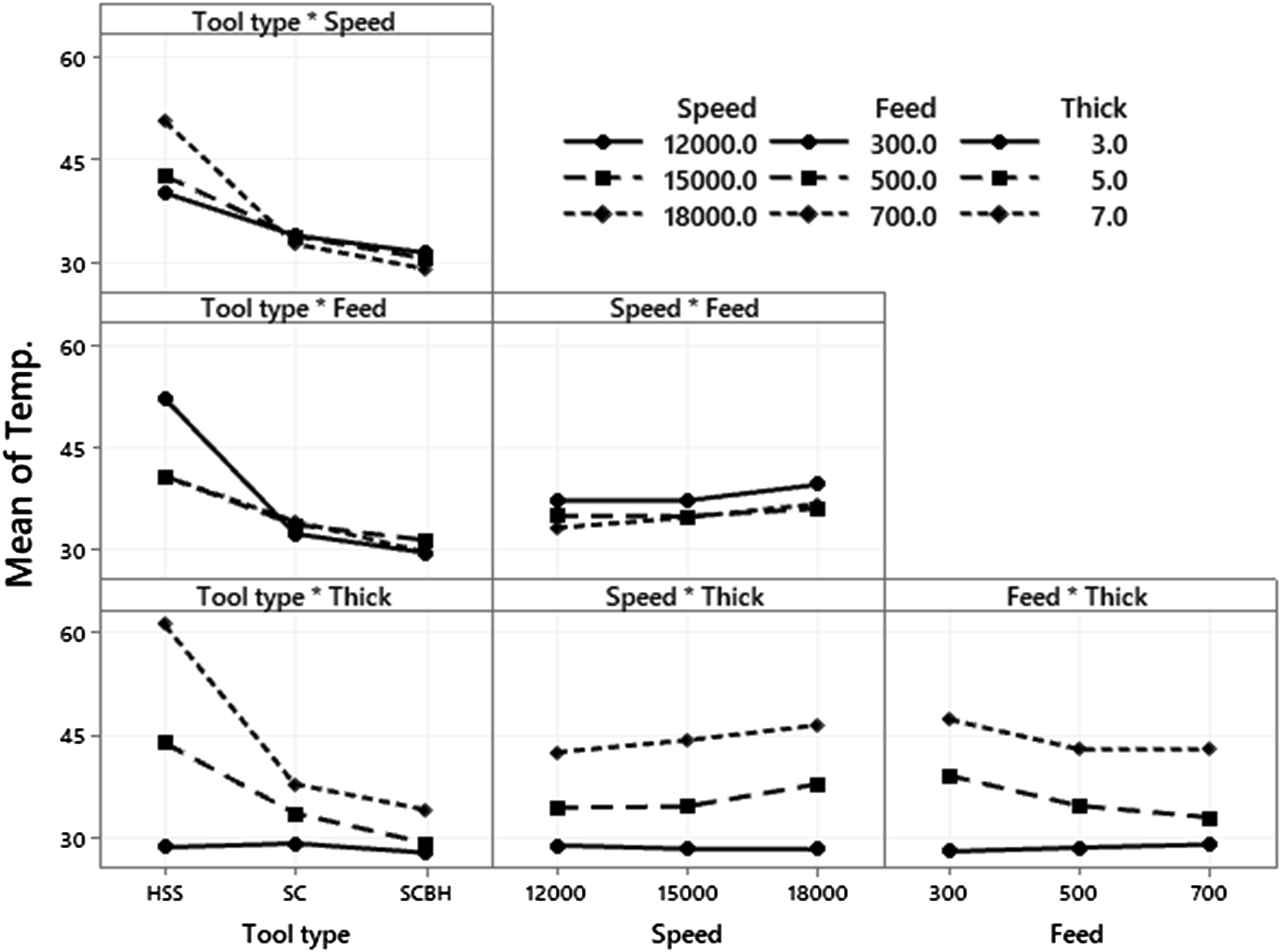
For the HSS tool, the high temperature was seen at a low feed rate (Figure 8(a)–(c)). The feed rate influence on the temperature using the SC and SCBH tools presented a slightly different behavior than the HSS (Figure 8(d)–(i)). The temperature was slightly increased with a rise in feed rate for SC and SCBH tools. The higher temperature was produced by HSS tools at higher speed compared to SC and SCBH tools which had lower temperature at higher speed. The temperature generated during drilling is crucial for polymer composites. The epoxy has a degradation temperature between 120°C – 270°C.
39
In this study, the generated temperature was found lower than 120°C. The thrust force was found directly relative to the temperature (Table 3, tests 27 and 46). Higher temperatures were noticed at a higher thrust force (Table 3, test 21, 24, and 27). The heat generated by friction between the tools and composite dissipates by the composite, the chips, and the atmosphere.
58
Low thermal conductivity materials produce high heat generation by preventing heat dissipation during the drilling operation.
25
Therefore, HSS tools generated higher temperatures than SC and SCBH during the drilling. Another reason for lower temperature generation for SC and SCBH than HSS may be their higher hot hardness and lower thermal expansion coefficient values due to presence of higher carbon and tungsten, or presence of coating material. These tools absorbed and diffused heat faster than the HSS tool and coupled with its helical flute design of the drill bit, assisted in drawing out the cutting chip while diffusing heat from the cutting tool and the cutting zone. The low thermal conductivity of HSS caused higher temperatures at the cutting zone compared to other drill bit grades.
59
Surface plot of temperature versus feed and speed, a), b), and c) for HSS tools, c), d), e), and f) for SC tools, and g), h), and i) for SCBH tool with varying thickness.
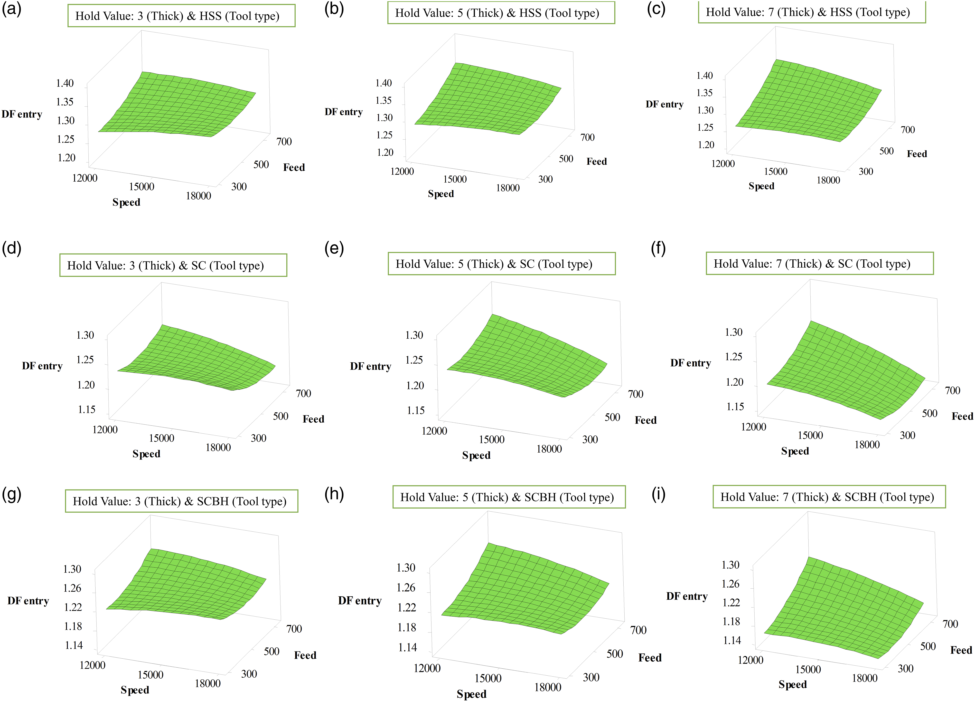
Concerning the DF, Figure 9(a) and 10 presented a main effect graph for the entry DF. It can be seen that all main drilling parameters have a crucial effect on the entry DF. The DF at the entrance was found to decrease with raising speed from 12,000 rpm to 18,000 rpm; this drop was significant for SC and SCBH tools (Figure 10). DF (entry) can be reduced, dropping the feed rate (Figure 10). Thickness showed a slightly different response; initially, the DF at entry was rising when thickness increased from 3 mm to 5 mm, followed by declination at 7 mm laminate thickness (Figure 9(a)). For all tested drilling conditions, SC and SCBH tools had a lower entry DF than the HSS tool. Test 66, as shown in Table 3, showed the lowest DF at the entrance, which was approximately 1.13 when drilling was performed by SCBH tool at speed (15,000 rpm), feed (300 mm/min), and thickness (7 mm), (Table 3, 66) as shown in Figure 3(c). Thrust force and temperatures at this delamination value were 8.5 N and 29.1°C, respectively. The highest entry delamination was around 1.39 for the HSS tool at 15,000 rpm, 700 mm/min, and 7 mm (as given in Table 3 in test 18), as shown in Figure 3. The thrust force and the temperature were recorded at around 24.5 N and 55.8°C, respectively. Considering the lower and higher DF entry conditions, higher thrust force and higher temperatures cause higher delamination. As shown in Figure 4, SC displayed excellent drill hole quality (entry) at higher speed, lower feed rate and higher thickness of composite (Table 3, test 48) compared to HSS (Table 3, test 21) and SCBH (Table 3, test 75) at identical conditions. Main effects plot for (a) entry DF, and (b) DF exit. Surface plot of DF (Entry) vs feed and speed, a), b), and c) for HSS tools, d), e) and f) for SC tools, and g), h), and i) for SCBH tool with varying thickness.
Similar behavior was found for the DF at the exit (as described in Figures 9(b) and 11). The DF at the exit was higher than at entry for all tested drilling parameters (Figure 3). A strong impact of the main drilling parameters on the exit DF can be seen. The DF at exit found abridging when speed turns up from 12,000 rpm to 18,000 rpm; however, the SCBH tool showed a slightly opposite response (Figure 11). A similar response was found for thickness; it declined with increasing laminate thickness (Figure 9(b)). In the case of feed rate, it was noticed to climb with the raising of feed rate (Figure 11). SCBH tools showed lower exit DF for all tested drilling conditions than HSS and SC tools. Test 75, as shown in Table 3, had the exit DF, which was around 1.18 for the SCBH tool at 18,000 rpm, 300 mm/min, and 7 mm (Figure 4(c)). The thrust force and temperature, nearly 10.1 N and 30.2°C, respectively, were at this drilling condition. As shown in Figure 4, SC displayed excellent drill hole quality (exit) at higher speed, lower feed rate and higher thickness of composite (Table 3, test 48) compared to HSS (Table 3, test 21) and SCBH (Table 3, test 75) at identical conditions. SCBH showed higher uncut fiber and fiber pull out compared to the SC tool, although matrix debonding was almost the same for both tools (Figure 4(b) and (c)). The highest DF was 1.57 for HSS tools at 12,000 rpm, 700 mm/min, and 5 mm (as given in Table 3 in test 8 and Figure 12(a)). The thrust force and temperature at this condition were around 19 N and 29.6°C. It can be concluded that the DF has a critical relation with the thrust force and temperature during the GFRP laminate drilling. When the thrust force increased, the drill entry DF increased due to high push-down force at the higher feed rates, which resulted in the tool bit forcing through the GFRP material rather than cutting through it. The matrix starts to fracture and chip, which leads to fiber out. Similarly, when the temperature exceeds the range of 46°C, the matrix will start to disintegrate and cause higher delamination due to premature glass fiber exposure when the matrix disintegrated.
60
Excellent drill hole quality can be achieved using SC drill bit due to lower thrust force than SCBH and HSS (Figure 4). Surface plot of DF (Exit) vs feed and speed, a), b), and c) for HSS tools, d), e) and f) for SC tools, and g), h), and i) for SCBH tool with varying thickness. a) highest DF (Exit) at 12,000 rpm, 700 mm/min, and 5 mm for HSS.

Optimization of the drilling performance of glass fiber reinforced polymer
As shown in Figure 13, residual plots for thrust force, drilling generated temperature, DF (entrance), and DF (exit), the normal probability plots for all drilling performances showed a similar trend with best fitted to the linear line. It shows the model used is useful to design the experiment, and results can be reasonable, which can be used to examine the drilling performance of the GFRP composite. Residual plots: (a) Thrust force, (b) drilling generated temperature, (c) DF (entrance), and (d) DF (exit).
The following regression equations (3)–(6) for thrust force, drilling generated temperature, and DF (entrance and exit) were developed using RSM to predict the drilling performance, where T: tool types, s: speed, f: feed rate, t: thickness.


Figure 14(a) represents the optimization plot for GFRP composite drilling. It can highlight that the best drilling condition is tool type, speed, feed rate, and thickness at levels 300, 18,000, 7, and SC, respectively. a) Optimization plot and b) drilled holes quality (Table 3, test 48).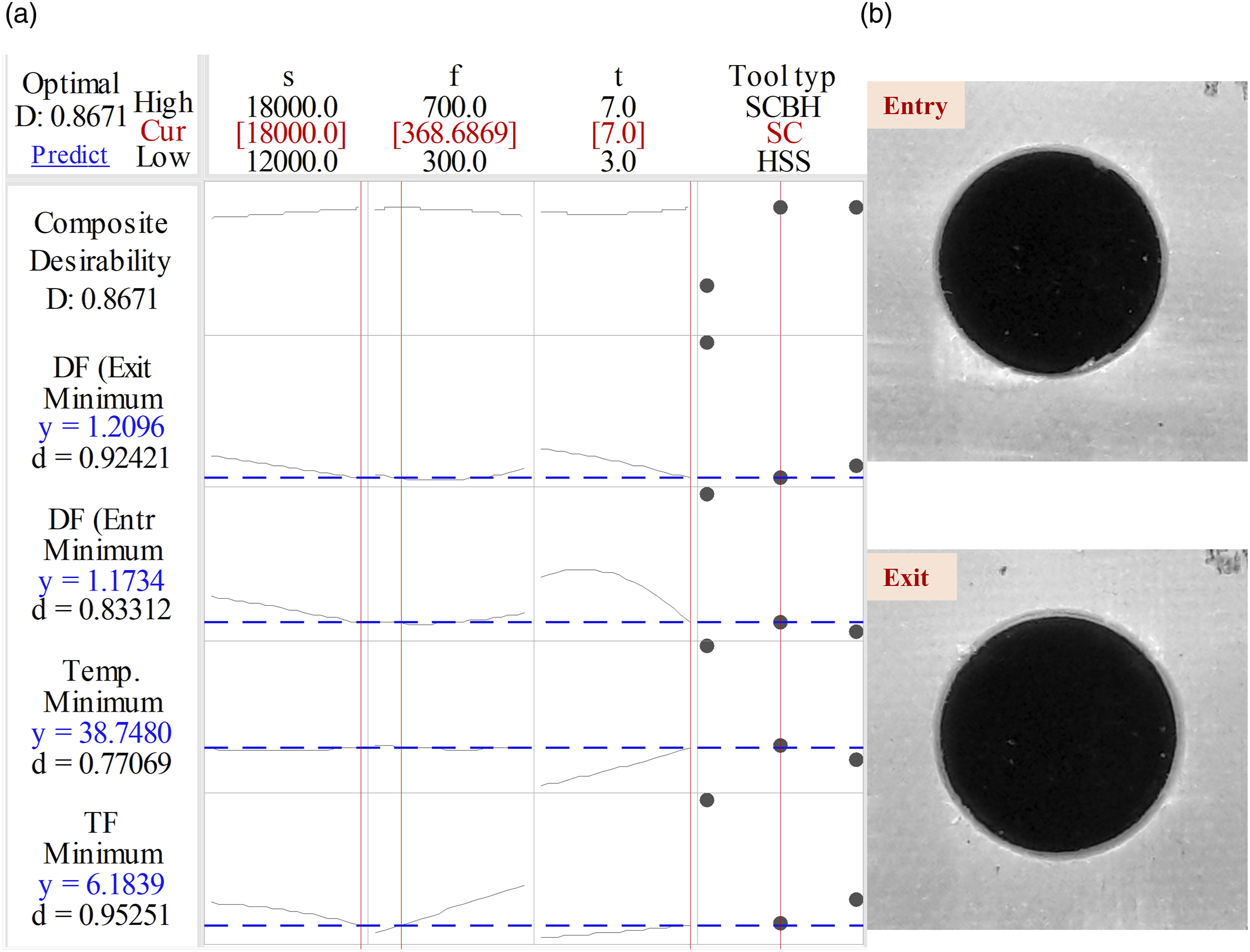
Drilling generated temperature and thrust force have the lower and higher desirability score (0.77,069 and 0.95,251, respectively) than composite desirability (0.8671) because the predicted responses of 34.7480 and 6.1839 are higher than the target of minimum 26.2°C and 4.8 N, respectively, but still inside the acceptable range. The drilled hole’s quality at 18,000 rpm, 300 feed rate and 7 mm thickness (Table 3, test 48) is given in Figure 14(b), with DF’s value at the entrance and exit as 1.18 and 1.19, respectively. The thrust force and drilling generated temperatures were 5.7 N and 35.5°C, respectively. It can be stated that the SC tool could be most suitable for better drilling performance for GFRP composite at a higher speed compared to the HSS and SCBH drill bits.
Validation was performed to determine the accuracy of the model. 10 random sets of drilling parameters were selected to perform the validation experiments for each drill bit grade. Three sets out of range parameter validation experiments were included in the random sets to determine the parametric adequacy range of the model. The prediction model was developed using RSM for each drill tool, shown from equations (7) to (12). The percentage error is calculated using equation (13). DF, 


Result of validation and adequacy test.

Conclusions
The drilling operation was done on the GFRP composite using various main input parameters such as tool type, speed, feed rate, and composite thickness. The thrust force, drilling generated temperature, and DF (at entry and exit) were examined for the drilling performance of GFRP composites. The HSS, SC, and SCBH twist drill bits were used to drill the hole at a high-speed range (12,000-18,000 rpm). 1. The results showed that the thrust force could be minimized significantly by reducing the speed, feed, and thickness when the HSS drill bit was used. However, SC and SCBH showed a different response for thrust force at variation speed, especially SC, which showed the lowest thrust force at a higher speed. 2. The drilling-generated temperature can be minimized at a lower speed and thickness. The temperature was almost constant with the speed and feed rate variation for SC and SCBH tools. HSS tool presented a decreasing trend (temperature) when the feed rate rose from 300 mm/min to 700 mm/min. 3. ANOVA and RSM were used to examine the drilling process of the GFRP composite. ANOVA analysis presents that all the input parameters, except speed and second-order interaction with tool type, substantially influence thrust force. The temperature, tool type, and thickness had a significant impact, besides the second-order interaction of the major parameters with tool type. The DF at entry and exit were found to be affected by the main parameters. The selection tool type had a critical impact on the DF at the entrance and exit compared to other drilling parameters. 4. The highest DF was found for HSS, and the lowest was for the SC and SCBH drill tool, which showed the benefit of using higher drilling speed for GFRP composite. However, HSS showed higher drilling temperature at low speed, high feed rate, and low thickness of GFRP but when drilling speed increased, delamination of HSS also increased. The type of delamination was matrix debonding, uncut fiber, and fiber pull out during drilling operation. 5. From RSM analysis, the regression equations were generated to predict the thrust force, temperature, and DF (at entry and exit). The best drilling performance was achieved by using the SC tool at a higher speed (18,000 rpm), higher thickness (7 mm), and lower feed rate (300 mm/min). The DF at entry and exit was found around 1.18 1 and 1.19, respectively, at 5.7 N (thrust force) and 35.5°C (temperature).
In conclusion, higher composite’s thickness with SC drill bit is recommended most suitable for drilling GFRP composite at a higher speed and lower feed rate than the HSS and SCBH . SCBH drill bits may also be utilized for a good quality hole, although it had higher thrust force than SC, which reduce tool life. The drilling process and performance method used in this study is recommended to manufacture GRFP laminates in aerospace, marine, and automotive industries, especially structural applications.
Footnotes
Acknowledgements
The authors thankfully acknowledge the support of the Centre of Advanced and Functional Materials (AFM). and Universiti Teknologi PETRONAS (via the graduate assistantship scheme).
Authors' contributions
Khurshid Malik: Methodology, Writing - original draft, Writing - review & editing. Faiz Ahmad: Supervision. Woo Tze Keong: Data curation. Ebru Gunister: Final review & editing.
Declaration of conflicting interests
The author(s) declared no potential conflicts of interest with respect to the research, authorship, and/or publication of this article.
Funding
The author(s) disclosed receipt of the following financial support for the research, authorship, and/or publication of this article: This work was supported by research grant Ministry of Higher Education, Malaysia (MOHE 0153 MA081).
Availability of data and material
Raw data is available with author on request.
Consent for publication
All authors have approved the manuscript and agree with its submission to Polymers and Polymer Composites.