
Abstract
The present work deals with the microwave-assisted compression moulding of high-density polyethylene (HDPE)-based composites. In the present work, 20 wt% of reinforcement in the form of kenaf and multi-walled carbon nanotube (MWCNT) was used to fabricate HDPE/kenaf and HDPE/MWCNT polymer composites. The mechanical characterizations of the microwave-processed composites were carried out in terms of uniaxial tensile test with different strain rate, multistep stress relaxation, flexural and impact test. The uniaxial tensile test revealed that the tensile modulus of microwave-processed four-layered HDPE/kenaf polymer composite was 35.2% higher than that of HDPE/MWCNT polymer composite. The HDPE/MWCNT polymer composite showed a minimum of 1.25 GPa and a maximum of 4.7 GPa of elastic modulus when tested at different strain rate. The impact energy absorbed by the HDPE/kenaf polymer composite (1.055 J) was 81.12% higher than the HDPE/MWCNT polymer composite (0.582 J).
Introduction
Advanced polymer composites are popular for different types of engineering applications due to their high specific strength-to-weight and specific-stiffness-to-weight ratio. Polymer-based matrix acts as a cushioning material to protect the fibres from the environment. However, advanced composite materials based on synthetic reinforcements (carbon, Kevlar, etc.) comprise of various issues related to environment, such as biodegradability and so on. The issue of the high cost of synthetic materials also limits their application in low load environments.
In recent years, fibres obtained from nature have emerged to replace traditional high-strength synthetic fibres to form a new class of natural fibre-reinforced polymer composites. The growing awareness of environmental concerns is also another element to force the engineering sectors to develop new materials from natural resources that are either reusable or renewable. 1,2
The properties of natural fibres differ according to their sowing condition, environmental condition, aspect ratio, processing parameter, cellulose, hemicellulose and lignin content. 3 To obtain the best property of the fibre, chemical or biological treatment should be done at the time of extraction. 4 Kenaf fibres have high strength, hence they are widely used. 5 Kenaf fibre belongs to the family of Hibiscus cannabinus (a plant of Malvaceae family). Kenaf is a lignocellulosic crop, which can grow up to 4–6 m, with 24 Mg/ha of yield in just 5–7 months. It is usually grown in subtropical and tropical parts of Africa and Asia. As the kenaf crop requires a low quantity of pesticides and herbicides, it is cheaply available than other natural fibres. 6,7
The major drawback of natural fibre is their rigidity. Hence, to provide the stiffness to the fibre, they are usually incorporated within a matrix. High-density polyethylene (HDPE) is a thermoplastic which is easily coupled with the microwaves. HDPE has a low melting temperature of 130–135°C; hence, it can be easily processed. Moreover, the impact resistance of HDPE composites is quite high. 8 HDPE is a linear unbranched polyethylene, whose molecular weight ranges from a few thousand to 3,00,000. In addition to its good impact resistance, HDPE is a good insulator, has low water absorption capacity and is chemically inert. 9
Multi-walled carbon nanotubes (MWCNTs) have unique physical, mechanical and chemical properties. 10 CNT-reinforced polymer composites have high strength, low weight and high toughness. It has been seen that the reinforcement of CNTs increased the flexural and elastic modulus of the composite. 11 Also, there is a decrease in the glass transaction temperature (T g), which helps to utilize less energy for the processing of the composites. 12,13 The surface of the CNTs is smooth, so there is the problem of adhesion with the matrix. 14 Also, the waviness of the CNTs in the CNT/polymer composites affects the mechanical properties of the composites. 15 To minimize this effect, compatibilizer can be used. The diffusivity of the compatibilizer, CNT and matrix should be in close contrast, so that the bonding between the interfaces is strong. 16 Furthermore, one of the most promising applications is that of conducting polymers, where the CNTs are incorporated as a filler into the polymer matrix. 17 Hence, they can be processed (heated) using microwave energy.
The conventional manufacturing routes for polymer composites have a longer cycle time. Therefore, there is a need to explore faster and energy efficient manufacturing route. Microwave processing could be a potential manufacturing route with increased speed and energy efficiency. Microwave heating is of volumetric nature thus uniform hating takes place. 18 –20 Volumetric heating of the material being processed results in short cycle times, improved material properties and energy savings. Furthermore, it is also known that microwaves can accelerate the curing rates of polymers at a frequency of 2.45 GHz. 21 Polymers come under the category of microwave absorbing materials. But they have a low value of dielectric loss factor, so they take more time to cure as compared to CNTs. In general, microwaves penetrate deep into the polymer composites, so more uniform heating is achieved.
Mohammed et al. studied the microwave temperature effect on the tensile properties of sugar palm-reinforced composite and found that 70°C gave the maximum tensile strength. 22 Sharma et al. studied the effect of aspect ratio on the mechanical properties of the MWCNT. They found that with high aspect ratio, there is effective stress transfer through the carbon tubes. Thus, the overall mechanical property of the composite is enhanced. 23 Zhou and Hawley investigated the curing time of the composite by a variable frequency method and found that microwave curing decreased the curing time drastically. 24 Li et al. studied the cure cycle and energy consumption of microwave-cured carbon fibre-reinforced polymer composite and found that microwave curing is 57.9% and 24.1% of the thermal cycle. 25 Rao et al. studied the Inter laminar shear strength (ILSS) property of microwave-processed glass–epoxy composite and found that the ILSS increased due to decreased viscosity. 26
The main objective of the present study is to investigate the comparative mechanical properties of 20 wt% HDPE/kenaf and HDPE/MWCNT composites. Kenaf may not match the strength of MWCNT due to the much higher fibre diameter than the MWCNT. However, MWCNT being costlier, thereafter its replacement with the kenaf-reinforced composite may be considered. The composites were fabricated using a novel manufacturing process of microwave-assisted compression moulding (MACM). Microwaves are known for their rapid heating rates due to energy conversion at the molecular level. Rapid heating could reduce the cycle time during the manufacturing of such composites. Therefore, in the present work, microwave energy was used to develop the MWCNT and kenaf-based composites. The detailed literature review indicated no paper on comparative mechanical performance evaluation of these composites fabricated using MACM process. Therefore, in the present work, comparative mechanical performance evaluation of the HDPE/MWCNT and HDPE/kenaf composites was carried out through uniaxial tensile test, strain rate-dependent tensile test, multistep stress relaxation test, flexural test and impact test.
Experimental procedure
Materials
In the present work, 20 wt% HDPE/MWCNT polymer pellets were procured from ‘Chengdu Organic Chemicals Co., Ltd, Chinese Academy of Sciences, Chengdu, China’. The average length and diameter of the procured pellets were 0.5 and 1.5 mm, respectively. The length of the MWCNTs was 10–30 µm (as per the supplier’s information). 27 The presence of MWCNTs in pellets have been confirmed by scanning electron microscopy (SEM) (make: FEI, Hillsboro, Oregon, USA; Model: NOVA-450). Figure 1(a) shows the HDPE/MWCNT pellets with the SEM micrograph of randomly distributed MWCNTs in the pellets. The pellets of virgin HDPE (HDPE-50MA180; shown in Figure 1(b)) were supplied by ‘Reliance Chemicals, Mumbai, India’.
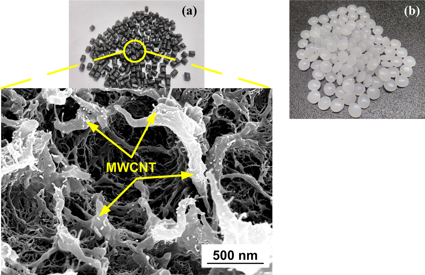
Images showing (a) HDPE/MWCNT pellets with SEM micrograph and (b) HDPE pellets.
Kenaf fibre mat was procured from ‘Go Green Products, Chennai, India’. The weave pattern of the kenaf fibre mat was plain weave. SEM micrograph of kenaf fibre mat (Figure 2) confirms the weave pattern. The average diameter (Φ 1) of the fibre is 0.98 mm. The diameter was calculated from the SEM micrograph. The diameter of the strand (Φ 2) present in fibre is 0.02 mm. The dielectric constant of materials used in the present work is tabulated in Table 1.
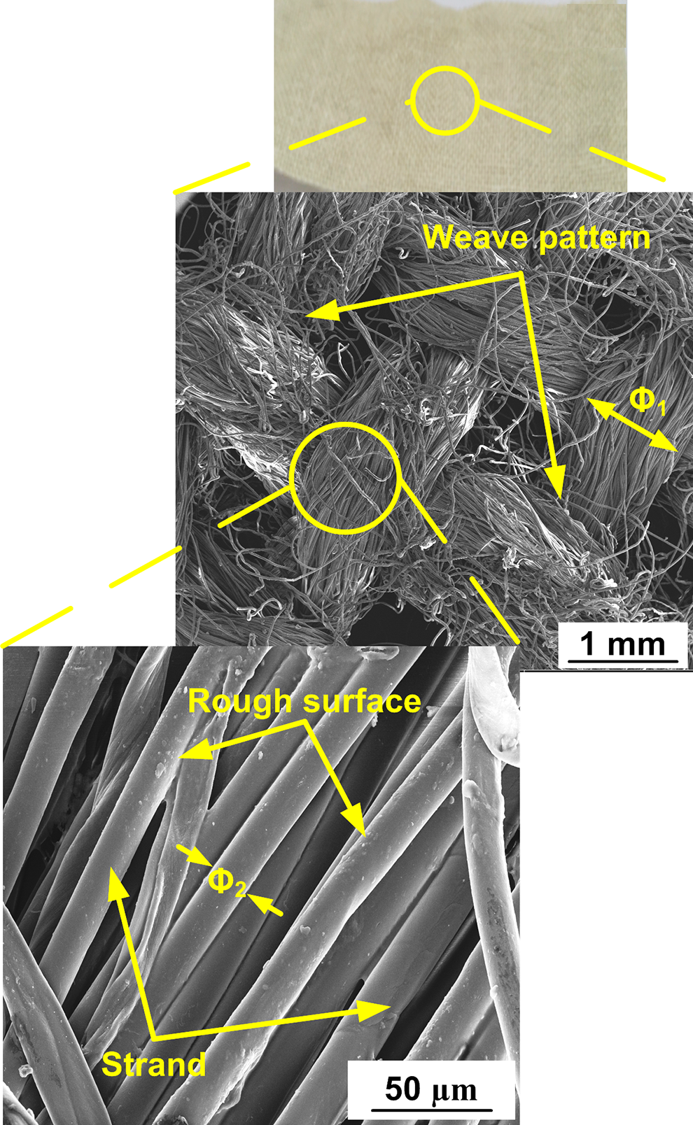
Treated kenaf fibre mat with SEM micrograph.
Dielectric constant and penetration depth of materials used.
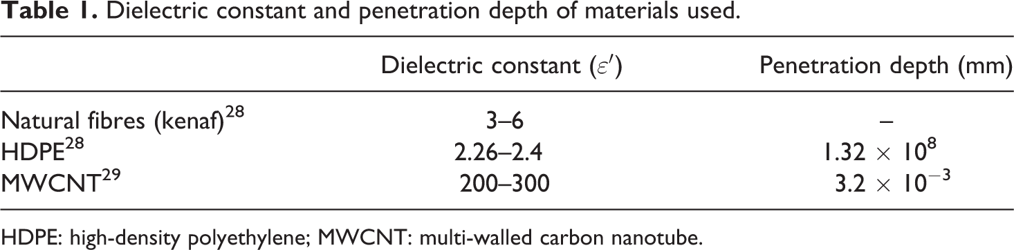
HDPE: high-density polyethylene; MWCNT: multi-walled carbon nanotube.
Fibre treatment
Pieces of kenaf fibre mat of size 140 × 50 mm2 were cut. Then, the fibres were washed in the distilled water to remove dust particles and pith from its surface. After washing the fibre, it was hot dried at 60°C for 12 h. After drying the fibre, the chemical treatment (NaOH) of kenaf fibre was carried to remove hemicellulose and wax, thus increasing the percentage of cellulose present in the fibre. For the chemical treatment, 2.5 M NaOH solution was prepared. The fibre mat was soaked in the solution at room temperature (22°C) for 24 h. The alkali-treated fibre mat was washed in the distilled water and hot dried at 60°C for 12 h, until no trace of alkali was left. A litmus paper test was used to ensure that there is no alkali left on the fibre surface. Figure 2 shows the rough surface of the strands after the fibre treatment.
Fabrication of HDPE/kenaf polymer composite
The 20 wt% of kenaf fibre is used to fabricate the HDPE/kenaf polymer composites. Pellets of HDPE and treated kenaf fibre mat were pre-weighed, to ensure the accurate weight percentage of reinforcement (fibre) loading. The HDPE/kenaf composites were processed using MACM in an alumina mould (make: VB Ceramics, Chennai) of size 150 × 56 × 15 mm3. Alumina being a low dielectric loss material is transparent to microwaves, thus allowing the microwaves to directly interact with the HDPE pellets and kenaf fibre placed in the mould. Other properties of alumina, such as high hardness, inertness, thermal and chemical stability, also make it a candidate material for the mould. 30,31
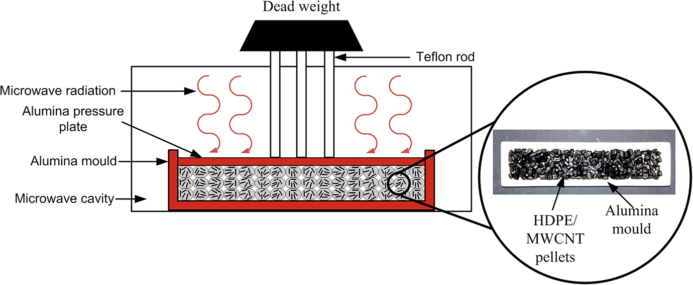
Four-layered HDPE/kenaf composite was prepared by stacking alternately kenaf layer between the HDPE matrix (shown in Figure 3). An equal proportion of pre-weighed HDPE pellets and kenaf fibre mat was maintained for each layer. While placing the HDPE pellets and kenaf fibre mat in the mould cavity, great care was taken to ensure 20 wt% of fibre loading. For processing natural fibre-reinforced composites, an industrial multimode microwave applicator (make: model: 700 DEG °C Premium; VB Ceramics) with a maximum output power of 1.1 kW operating at 2.45 GHz was used.
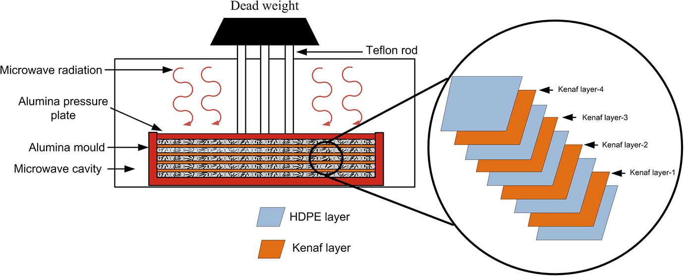
Schematic representation of the experimental setup for HDPE/kenaf polymer composite.
After placing the kenaf fibre and HDPE pellets in the alumina mould, the mould was covered with the alumina pressure plate. To ensure proper bonding and to minimize the porosity between layers, the pressure was applied using dead weight as shown in Figure 3. Figure 4 shows the processed HDPE/kenaf polymer composite. IR pyrometer (make: model: RAYXRTG5SFA; Raytek, Germany) was used to monitor the temperature of the composite during microwave processing. The processing of the composite takes place by the combined action of pressure (due to dead weight) and microwave heat. After the trial and error process, an optimum microwave power, exposure time and pressure were selected, as shown in Table 2. 28 The heating of the sandwich composite takes place due to heat being transferred from kenaf fibre to polymer sheet. This is due to a higher dielectric constant of kenaf fibre than the HDPE pellets. 28
Optimum process parameters for the processing of the polymer composites.
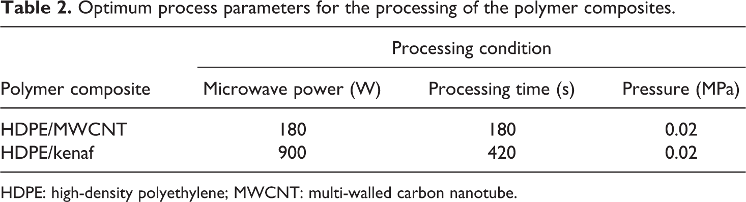
HDPE: high-density polyethylene; MWCNT: multi-walled carbon nanotube.
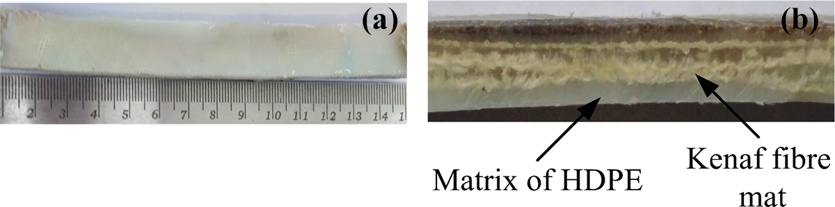
Microwave-processed polymer composite of HDPE/kenaf (a) top view and (b) cross section.
Fabrication of HDPE/MWCNT polymer composite
To fabricate the HDPE/20 wt% MWCNT polymer composite, same fabrication technique was used as discussed above. The heating of the polymeric materials is mainly dependent on the electric field of microwave. Dielectric constant is the influential parameter on which microwave heating of polymer composites depends. As CNTs have higher dielectric properties (Table 1) comparing to HDPE and kenaf, hence they couple with the microwaves very fast. 32 Therefore, the processing time required to fabricate HDPE/MWCNT composites was 57% lesser than HDPE/kenaf composites. Figures 5 and 6 show the experimental setup and microwave-processed HDPE/MWCNT polymer composite, respectively. The process parameters for microwave processing of HDPE/MWCNT composite were optimized using trial and error method and the same are presented in Table 2. 27
Schematic representation of the experimental setup for HDPE/MWCNT polymer composite.
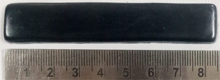
Microwave-processed HDPE/MWCNT polymer composite.
Characterization of the composites
Tensile test
Uniaxial tensile test of the microwave-processed specimens was conducted on a universal testing machine (make: mode: H50KS; Tinius Olsen, UK). All the specimens were conditioned for at least 24 h prior to the test. The uniaxial tensile test was conducted according to the ASTM D3039. The dimension of the HDPE/kenaf and HDPE/MWCNT composite was 85 × 18 × 4 mm3 for the uniaxial tensile test. Five samples of each polymer composite were tested to ensure the repeatability of the test data. The strain rate of 1 mm/min was chosen for the uniaxial test. The failure mechanism of specimens was investigated using SEM.
Strain rate-dependent tensile test
There are situations when the strain rate changes during the loading. In such condition, the composites show different properties at the different strain rates. This section shows the sensitivity of HDPE/MWCNT and HDPE/kenaf polymer composites at the different strain rates. The strain rate-dependent tensile test of microwave-processed specimens of HDPE/MWCNT and HDPE/kenaf polymer composites was conducted on the universal testing machine (make: model: H50KS; Tinius Olsen). The strain rate-dependent experiments were conducted at the strain rates of 1, 5, 10, 20 and 40 mm/min. The dimension of the composites was taken as 85 × 18 × 4 mm3 during the test. Five samples of each polymer composite were tested to ensure the repeatability of the test data.
Multistep stress relaxation test
Stress relaxation describes how polymers relieve stress when the strain was held. With the increase in the strain holding time, the decrease in the stress value increases. Thus, to describe the stress relaxation response of microwave-processed HDPE/MWCNT and HDPE/kenaf polymer composite, the test was conducted at the strain rates of 5, 10 and 20 mm/min. The stress relaxation test of microwave-processed polymer composites was conducted on the universal testing machine (make: model: H50KS; Tinius Olsen). At the start of the test, the stress is allowed to increase for 20 s, and then strain is held for the next 20 s (it makes one complete cycle of 40 s). After holding period, test was again continued for another 20 s and then again strain was held for 20 s. Similarly, the test was continued until the failure of the specimen occurs. Five samples of each polymer composite were tested to ensure the repeatability of the test data.
Flexural test
Three-point bending test was used to determine the flexural behaviour of the HDPE/kenaf and HDPE/MWCNT polymer composites. The flexural test was performed as per ASTM D7264. The span length to thickness ratio was taken as 16:1, and the width of the specimens was 13 mm. The span length for HDPE/kenaf and HDPE/MWCNT polymer composites was maintained at 64 mm, while thickness for HDPE/kenaf and HDPE/MWCNT polymer composites was 4 mm. The three-point bending test was conducted on the universal testing machine (make: Model: H50KS; Tinius Olsen). The test speed was set at 1 mm/min. Five samples of both types of polymer composite were tested. Figure 7 shows the experimental setup of the three-point bending test.
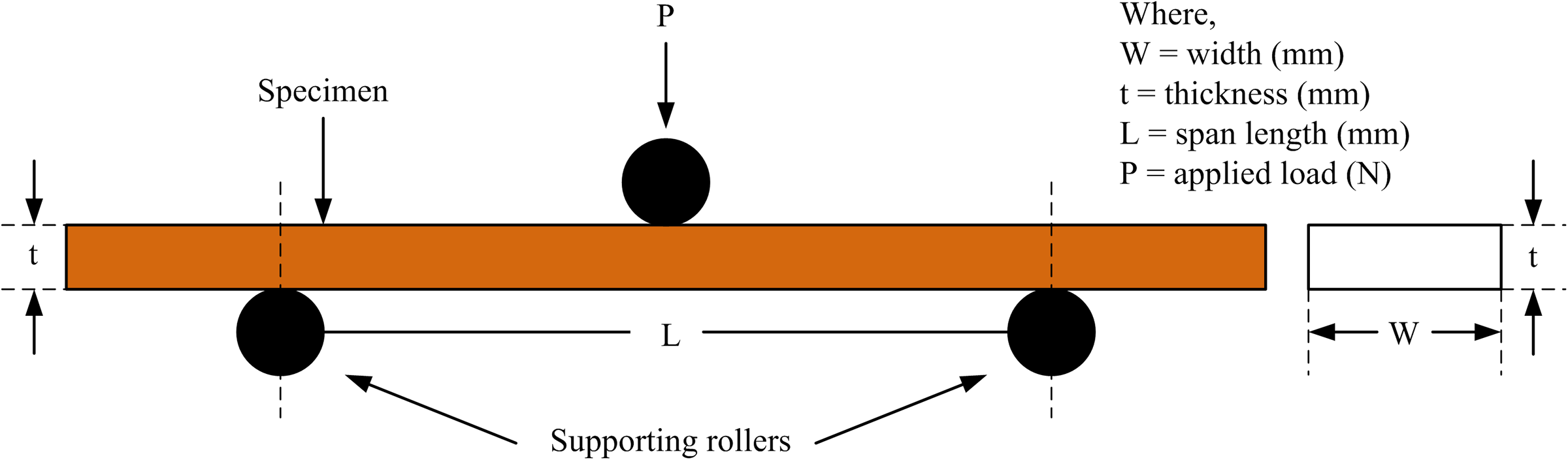
Experimental setup for the three-point bending test.
Izod impact test
Izod impact test was used to determine the energy absorbing capacity of the notched composite. Five samples of each type were tested on Izod impact tester (make: model: AE-ICIT; Izod/Charpy Tester, Advance Equipments, Mumbai, India). ASTM D256 was followed to determine the energy absorbing capacity of the composites. Prior to the test, all the specimens were conditioned at room temperature for 24 h. The dimensions of the specimen are specified as 64 × 12.7 × 4 mm3.
Results and discussion
Tensile test
Figure 8(a) shows the engineering stress versus strain curve of HDPE/MWCNT and HDPE/kenaf polymer composites. It can be observed that the ultimate stress of HDPE/MWCNT is 19.1 MPa, whereas for HDPE/kenaf, it is 17.8 MPa. HDPE/MWCNT polymer composite shows a 7.30% higher ultimate stress than HDPE/kenaf. The higher ultimate stress of HDPE/MWCNT polymer composite may be due to the presence of CNTs in the HDPE pellets. The reason behind the higher strength of HDPE/MWCNT polymer composite is discussed below. Despite the fact, HDPE/MWCNT composite having the higher ultimate stress, it has lower toughness than the HDPE/kenaf composite. The calculated area under the curve (from Figure 8(a)) for HDPE/MWCNT was 0.941 kJ, while for HDPE/kenaf, it was 1.093 kJ (approximately 13% higher). The lower toughness of HDPE/MWCNT is due to the presence of MWCNTs, which makes the polymer composite slight brittle as compared to HDPE/kenaf due to its cross-linked structure.
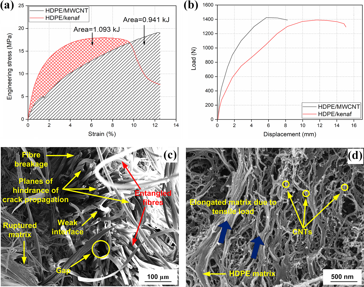
Tensile test (a) engineering stress versus strain and (b) load versus displacement curve. SEM fractographs of tensile fractured (c) HDPE/kenaf and (d) HDPE/MWCNT polymer composite.
Another important observation from the stress versus strain curve is the elastic modulus of the polymer composites. The elastic modulus of the composites has been recorded using extensometer during the tensile testing of the polymer composites. It has been found that the tensile modulus of HDPE/MWCNT polymer composites is 1.25 GPa and that of the multilayered HDPE/kenaf is 1.69 GPa. The higher modulus of HDPE/kenaf is due to its multilayers. During the test, when the crack propagates from the matrix to the fibre, each layer of kenaf in the matrix hinders the path of the crack (same can be observed from Figure 8(c)). When the crack propagates from the matrix to fibre, each strand of the fibre resists the crack growth. It can be observed from Figure 8(c) that consecutive strands are elongated during the testing, making each layer as the plane for the crack hindrance. Therefore, for the propagation of crack, more force is required. Hence, the tensile modulus of HDPE/kenaf is higher than that of HDPE/MWCNT polymer composite.
Figure 8(b) represents the load versus displacement curve of HDPE/MWCNT and the HDPE/kenaf polymer composite. From Figure 8(b), it is depicted that displacement of the HDPE/kenaf composite is more than the HDPE/MWCNT polymer composite. It means the HDPE/kenaf composite is more ductile than the HDPE/MWCNT composite. The load carrying capacity of the HDPE/MWCNT composite is more than the HDPE/kenaf composite for the same value of the displacement. This may be due to the higher value of stiffness of CNTs as compared to kenaf in the HDPE matrix.
Figure 8(c) and (d) shows the SEM fractographs of the fractured specimens of HDPE/kenaf and HDPE/MWCNT polymer composite during the uniaxial tensile test. It can be seen from Figure 8(c) that there is a gap between the fibre and matrix of the HDPE/kenaf polymer composite. When the HDPE/kenaf polymer composite is loaded in the longitudinal direction, due to the weak interface between the fibre and matrix, the load transferring capacity of the matrix to fibre decreases. Whereas Figure 8(d) (HDPE/MWCNT polymer composite) shows the strong interaction of the CNTs with the HDPE matrix. The strong interaction of the CNTs with the HDPE matrix may be the reason behind the higher ultimate strength of the HDPE/MWCNT polymer composite.
Strain rate-dependent tensile test
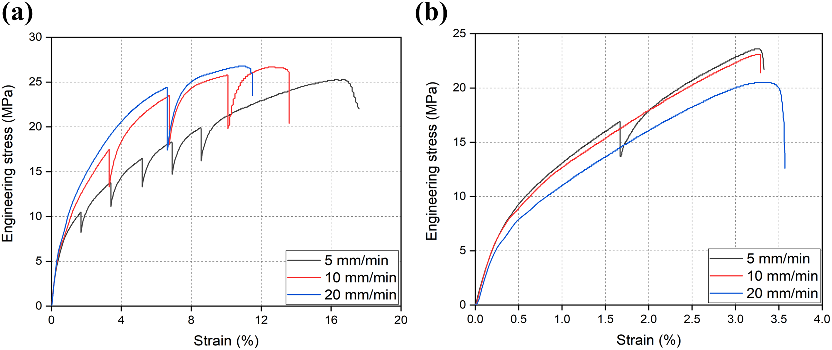
Figure 9(a) and (b) shows the engineering stress versus strain curve for the HDPE/kenaf and HDPE/MWCNT polymer composite, respectively. It can be observed from the curves that as the strain rate is increased, there is an increase in the ultimate stress of the composites. The increase in ultimate stress is due to the strain hardening of the polymer composites. With the increase in the strain rate, the ductility of the polymer composites decreases. 33 –37 Lower the ductility of the material, higher is the ultimate stress of the material. From Figure 9(a), it can be observed that the strain to failure increased with the increase in the ultimate stress up to 10 mm/min. Hence, it can be concluded that the toughness of the HDPE/kenaf composites increased with the increased strain rate. Whereas, in the case of HDPE/MWCNT composites (Figure 9(b)), the value of the failure strain was nearly the same for all the different strain rates. Due to the presence of MWCNTs within the HDPE matrix, the HDPE/MWCNT has lower elongation and necking as compared to HDPE/kenaf composite, which can be observed from Figure 9. The stress reduction after the onset of necking was at approximately 6.3% of strain in case of HDPE/MWCNT, whereas, in the case of kenaf it was 12%. This is possibly due to the fibrillar and cross-linked nanostructure of the nanotube network that is slightly more brittle than the kenaf fibre. The response of the MWCNT networks can be described as a combination of the cross-linked brittle polymer and the fibrillar plastic polymer stretching behaviours.
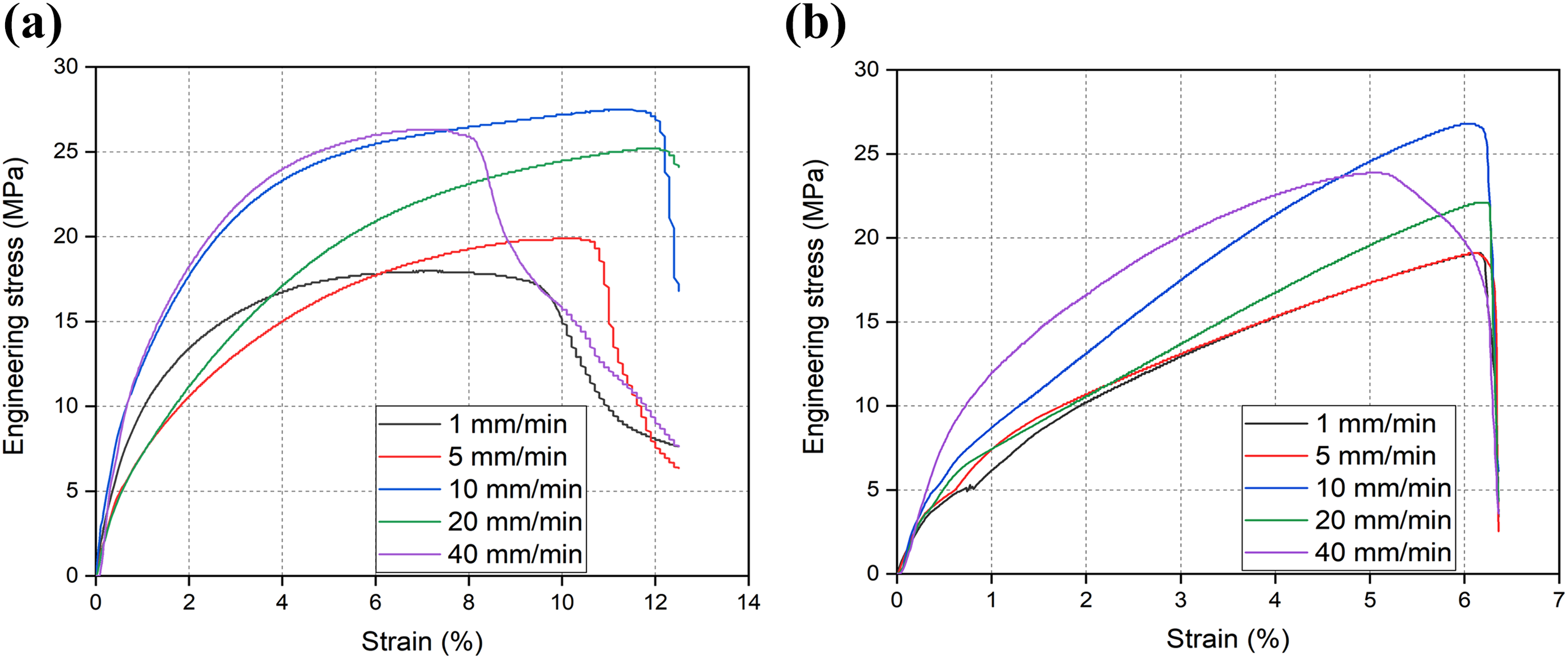
Engineering stress versus strain curve at different strain rate for (a) HDPE/kenaf and (b) HDPE/MWCNT composite.
When the strain rate was further increased from 10 mm/min to 20 mm/min, there was a decrease in the ultimate stress of both the polymer composites. The decrease in ultimate stress is due to the strain softening of the polymer composites. 33,34 With the increase in the strain rate above 10 mm/min, due to adiabatic heating, the polymer composites soften. This strain softening results in the drop of ultimate stress value for the HDPE/kenaf and HDPE/MWCNT polymer composites. The elastic modulus of the polymer composites is seen to be strain rate sensitive. The increase in strain rate shows a reduction in the ductility of the material. 33,34 Hence, the slope of the strain–strain curve increases. Table 3 shows the elastic modulus of the HDPE/MWCNT and HDPE/kenaf composite. From Table 3, it can be observed that there is a slight increase in the elastic modulus of the HDPE/kenaf composite. Whereas the elastic modulus of HDPE/MWCNT composite almost gets double each time as the strain rate is increased up to 10 mm/min.
Elastic modulus at different strain rates.
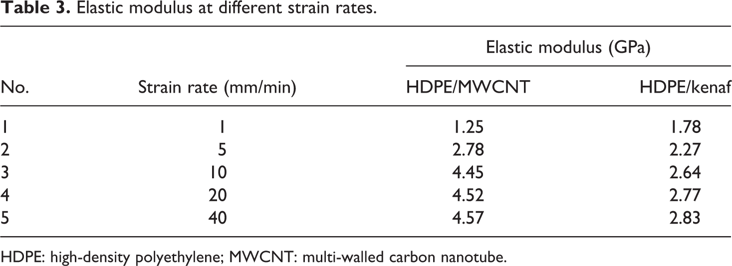
HDPE: high-density polyethylene; MWCNT: multi-walled carbon nanotube.
Multistep stress relaxation test
Figure 10 shows the stress relaxation curve for HDPE/kenaf and the HDPE/MWCNT polymer composite. It can be observed from Figure 10(a) and (b) that at all the strain rates, the ultimate stress value for the HDPE/kenaf polymer composite is higher than that of HDPE/MWCNT composite. As the HDPE/kenaf composites are ductile than HDPE/MWCNT composites, it distributes the larger stress within the material, when the strain is held for a period of 20 s.
Stress relaxation curve for (a) HDPE/kenaf and (b) HDPE/MWCNT polymer composite.
Comparing Figure 10 with Figure 9, it can be observed that the ultimate stress value of both the polymer composites increased in the step relaxation test. The increase in ultimate strength is due to the reorientation of the molecular chain. When the material is loaded, the molecular chain changes the orientation. Upon holding the strain, there is reorientation of the molecular chain. 34 This reorientation increases the ultimate strength of the polymer composites. From Figure 10(a), it can be depicted that as the strain rate is increased, the drop in the stress during the holding period increases. It can be observed from Figure 10(a), for 5 mm/min strain rate, the increase in ultimate stress value is 42.13% higher than that for 5 mm/min at static loading (comparing the graph with Figure 9(a)).
When the strain rate is increased from 5 mm/min to 10 mm/min, the number of holding steps dropped down to three for the HDPE/kenaf composite. There is not much increase in the ultimate stress at 10 mm/min in comparison to 10 mm/min of static loading. A similar trend can be observed with the HDPE/MWCNT polymer composite (Figure 10(b)). At 5 mm/min, there is an increase in the ultimate stress, but as the experiment is conducted for a cycle of 40 s, therefore only one step could be observed in the drop of stress. When the strain rate increased for the HDPE/MWCNT polymer composite, no step in a drop of stress value is observed, because the material fractures within 20 s of the loading condition.
Flexural test
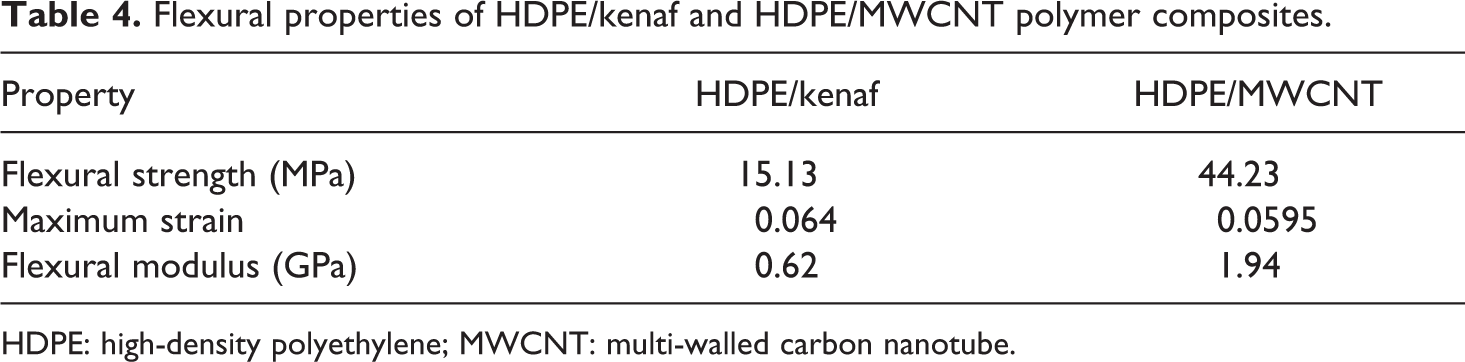
The three-point bending test has been done to determine the flexural strength, flexural strain and the flexural modulus of the composites using equations (1) to (3), respectively. Figure 11(a) and (b) shows the bend specimens of HDPE/MWCNT and HDPE/kenaf, respectively, after the flexural test. Table 4 shows the flexural properties of HDPE/kenaf and HDPE/MWCNT polymer composites.
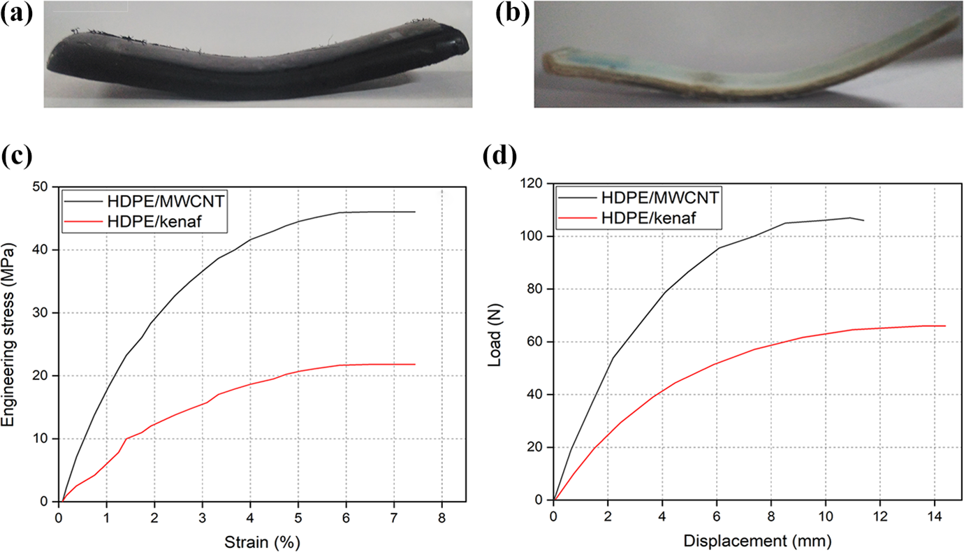
Flexural tested specimen of (a) HDPE/MWCNT and (b) HDPE/kenaf polymer composite. Flexural (c) engineering stress versus strain and (d) load versus displacement curve of HDPE/MWCNT and HDPE/kenaf polymer composite.
Flexural properties of HDPE/kenaf and HDPE/MWCNT polymer composites.
HDPE: high-density polyethylene; MWCNT: multi-walled carbon nanotube.
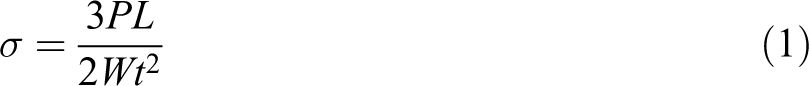
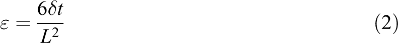
where σ, ε and Ef are the flexural strength, flexural stain and flexural modulus, respectively. P, L, W, t, δ and m are maximum load, span length, width, thickness, deflection of the composite and slope of the secant of the load–displacement curve, respectively.
Figure 11(c) and (d) shows the engineering stress versus strain and load–displacement curve of the polymer composites. It can be observed from Figure 11(c) and (d) that the flexural stress and load-bearing capacity of HDPE/MWCNT are greater than the HDPE/kenaf polymer composite. From Table 4, it can be observed that the flexural strength of HDPE/MWCNT polymer composite is 192.33% higher than that of HDPE/kenaf polymer composite. It may be due to the presence of CNTs within the HDPE matrix, which increases the overall stiffness of the composite. As stronger the filler, higher will be the strength of the composite.
From Table 4, it can be observed that the flexural modulus of HDPE/MWCNT polymer composite is 1.94 GPa which is 212.90% higher than that of HDPE/kenaf. The value of the modulus is directly dependent on the applied load. From Figure 11(b), it can be observed that the HDPE/MWCNT polymer composite has a higher load-bearing capacity in the through-thickness direction. Natural fibres generally have lower values of mechanical properties in the through-thickness direction. HDPE/kenaf polymer composite is not that stiff to carry the load in the through-thickness direction as that of HDPE/MWCNT polymer composite. Hence, the flexural modulus of HDPE/MWCNT polymer composite is higher.
Izod impact test
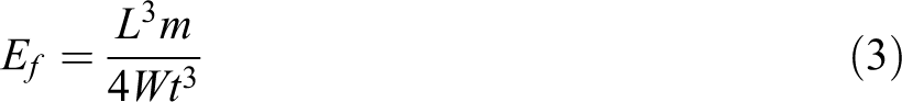
Figure 12(a) shows the impact energy versus angular displacement curves for HDPE/MWCNT and HDPE/kenaf polymer composite. The polymer composites were made to strike by the hammer of 2.71 J of energy. From Figure 12(a), it can be observed that the HDPE/kenaf absorbed 1.055 J of impact energy and HDPE/MWCNT absorbed 0.582 J of impact energy. Thus, HDPE/kenaf composites absorbed 81.12% higher impact energy than HDPE/MWCNT composites. Since HDPE/kenaf composite is ductile than HDPE/MWCNT composite, hence it absorbs more impact energy prior to the failure. The higher toughness of the HDPE/kenaf polymer composite can also be assured from the tensile load–displacement curve (Figure 8(b)). It can be observed that the HDPE/kenaf has higher displacement, that is, the material stretches more in the longitudinal direction, thus it has higher energy absorbing capacity than the HDPE/MWCNT polymer composite. Figure 12(b) and (c) shows the SEM fractographs of the fractured HDPE/kenaf and HDPE/MWCNT polymer composites. It can be observed from Figure 12(b) and (c) that the matrix and fibres shear in the direction of the applied load. Figure 12(b) shows the Kenaf fibre elongated in the load direction. Figure 12(c) shows the CNT pullout and the shearing of the HDPE matrix in the direction of the impact. It can be observed from Figure 12(c) that there is agglomeration of the CNTs in the matrix. This may be due to the higher percentage of dispersed CNTs within the matrix.
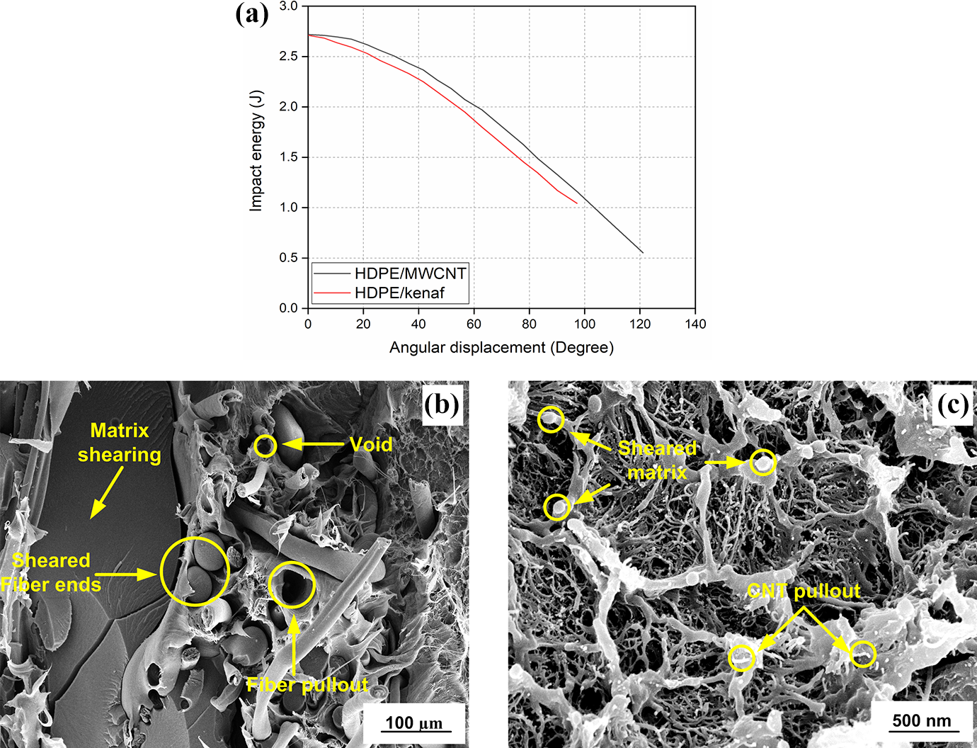
(a) Impact energy versus angular displacement curves. SEM fractographs of impact fractured. (b) HDPE/kenaf. (c) HDPE/MWCNT polymer composite.
Conclusion
Present work deals with the microwave processing of kenaf- and MWCNT-reinforced HDPE composites. The composites have been fabricated with 20% reinforcement. The microwave-processed HDPE/kenaf and HDPE/MWCNT composites were tested for their mechanical performance using various tests. The results discussed above support the following conclusions: The tensile modulus of microwave-processed HDPE/kenaf polymer composite is 35.2% higher than that of HDPE/MWCNT polymer composite. While the ultimate stress of HDPE/MWCNT polymer composite is 7.30% higher than that of HDPE/kenaf polymer composite. Tensile test at different strain rates showed that the tensile modulus increases with the increase in the strain rate. But the ultimate stress drops beyond 20 mm/min of strain rate for the polymer composites. When the composites were tested for a multistep stress relaxation test, it was observed that the increase in ultimate stress for the HDPE/kenaf polymer composite at 5 mm/min is 42.13%. With an increase in strain rate, the number of holding steps decreases. From the flexural test, it was observed that the flexural modulus of HDPE/MWCNT polymer composite is 212.9% higher than that of HDPE/kenaf polymer composite. HDPE/kenaf polymer composite absorbed 81.12% higher impact energy than HDPE/MWCNT polymer composite in the Izod impact test. The HDPE/kenaf composite has higher energy absorbing capacity due to the ductile nature of kenaf. Therefore, HDPE/kenaf can be a low-cost alternative for HDPE/MWCNT. Therefore, it may be used in automobile parts, sports equipment and so on.
Footnotes
Funding
The author(s) disclosed receipt of the following financial support for the research, authorship and/or publication of this article: The authors gratefully acknowledge the financial support of the Ministry of Human Resource and Development (MHRD), Government of India for this work.