
Abstract
Damage due to delamination is an important issue during drilling in glass-fiber-reinforced plastic composite laminates. Feed-rate during drilling is the most critical parameter. High feed-rate during drilling results in high thrust force on the composite laminate. In this work, dynamics of drilling in glass-fiber-reinforced plastic composite laminates are captured in the form of third-order state-space model between thrust force and feed-rate. Optimal control is then used to control the thrust force generated during drilling. Research has revealed that there is a critical limit on thrust force during drilling in composite laminate below which no delamination occurs. This critical thrust force profile is used in this work as reference in the optimal controller to ensure delamination-free drilling. Present controller precisely tracks the given critical thrust force reference profile and gives optimal feed-rate profile. The glass-fiber-reinforced plastic composite laminate is then drilled at this optimal feed-rate profile to obtain delamination-free holes. Delamination around the holes is quantified in the form of a delamination factor. Experimental results show that the control strategy is efficient and effective in preventing drilling-induced delamination in glass-fiber-reinforced plastic composite laminates.
Introduction
Polymer matrix composites (PMCs) have come up in a big way in recent years as an alternative of conventional materials for providing engineering material solutions. PMC is fabricated by reinforcing hard and brittle fiber layers in a softer polymer matrix. These materials satisfy designer’s requirements as they have high strength, light weight, high specific strength, good toughness, high specific stiffness, good corrosion resistance and so on. Glass-fiber-reinforced plastic (GFRP) composites having unidirectional or woven fibers as fillers are most widely used type of PMCs in automobile, aerospace, sports goods, wind energy, marine industry and so on. Composite products having simple shapes can be fabricated using primary processes such as hand lay-up, compression molding, pultrusion and filament winding. Complex product designs require assembly of different parts which require drilling in the composite laminates. Uncontrolled drilling can cause damage around the hole due to delamination of laminas at entry and exit of drill. Delamination occurring at entrance of drill into composite laminate is called peel-up delamination, while that at exit is called push-down delamination.1–3 Delamination during drilling is primarily caused by high thrust force acting on the composite laminate4,5 and is strongly dependent on feed-rate used during the drilling operation.6,7 High feed-rates produce high thrust forces leading to damage due to delamination at entry or/and exit of the drill. 8 Damage due to delamination reduces the strength and stiffness of the composite laminate. For the case of a unidirectional laminate, the actual shape of damage due to delamination is elliptical with principal directions parallel and transverse to the fibers. 9 For multidirectional composite laminates, the shape of damage due to delamination is approximately elliptical.10,11 There is a critical limit on the thrust force during drilling in composite laminate below which delamination does not occur.12,13
Damage due to delamination caused by thrust force acting on composite can be analyzed using fracture mechanics theory. Thrust force acting on the composite laminate during drilling operation produces deflection in the direction of drilling operation. Displacement due to this deflection can be calculated assuming uniform loading and using linear elastic theory for deflection of thin composite laminates. 14 Work energy produced by thrust force higher than critical limit cracks the composite laminate around the hole in a circular or elliptical shape and increases internal energy resulting in delamination. 15 Critical thrust force during drilling, below which no delamination occurs in a composite laminate, can be obtained using linear elastic fracture mechanics (LEFM) theory.12,15–19 Critical thrust force can be experimentally correlated with the feed-rate using curve fitting. 17
Different approaches in experiments can be used to prevent delamination during drilling in composite laminates. Use of back-up plate below the workpiece during drilling operation reduces the damage due to delamination. 20 Thrust force generated during drilling in GFRP laminate is affected by number of holes drilled with a given cutting tool, feed-rates, cutting speeds and drill geometry. At higher cutting speeds, thrust force generally increases after the tool wears out. Therefore, composite laminate is prone to de-bonding at the entry of drill bit when high cutting speeds are used in drilling with a blunt tool.21,22 Delamination increases with increase in feed-rate, while drilling in carbon-fiber-reinforced plastic (CFRP) composite laminates (a type of PMC) at spindle speeds of 4000 and 8000 r/min. At a high speed of 40,000 r/min, heat generated by friction between major and minor cutting edges of the drill and composite material promotes softening of polymer matrix. This results in delamination being not drastically affected by feed-rates at high cutting speeds.23,24 A combination of high speed, low feed and low-point angle of the drill is effective to minimize the delamination factor during drilling in composites.25–27 Vibration-assisted drilling in CFRP composites can be done with minimal damage at exit side using combination of high-speed and low to medium feed-rates, assisted with high-frequency vibrations of the tool that ensure intermittent cutting. 28 Cutting parameters such as spindle speed, feed-rate, drill diameter, point angle, nose radius, rake angle of the chisel edge, web thickness and fiber orientation can be used as input to predict thrust force generated during drilling in composite laminates. This model can be used to optimize the cutting parameters and tool geometry for delamination-free drilling. 29 Cutting parameters and boundary conditions can be appreciably optimized so as to obtain minimal delamination during drilling operation in PMCs, but delamination-free holes with high productivity have not been achieved. 30 This has prompted researchers to use classical/modern control theories for controlling thrust force during drilling in composite laminates.
Control techniques such as fuzzy logic 31 and neural network32,33 give good results in the absence of mathematical model of the process. Fuzzy logic can be employed to model dynamics of drilling in CFRPs using auto-regressive-moving-average (ARMA)-based linear equations between thrust force and feed-rate. Fuzzy controller can be given a second-order thrust force reference having critical damping ratio to control the thrust force. 31 Neural network can be used to model dynamics of drilling in composites with feed-rate and thrust force data as input. Critical thrust force model developed using the LEFM approach 12 can be used as reference thrust force for the controller. A neural controller can then be used to control the feed-rate to achieve desired thrust force during drilling.32,33 Surface roughness and delamination of fiber-reinforced plastics (FRPs) can be estimated using neural network as a function of feed-rate, speed, drill diameter and point angle.34–36 While drilling, thrust force varies with feed-rate, and dynamics of the system can be represented in the form of a transfer function between them. Transfer function consists of zeros (numerator terms) and poles (denominator terms) providing qualitative as well as quantitative insight into response characteristics of the system. First-order transfer function between thrust force and feed-rate can be obtained from experiments carried under various cutting conditions, wherein thrust force varies with respect to time in response to step change in feed-rate. 37 Similarly, third-order transfer function with delay between thrust force and feed-rate can be obtained from variation in thrust force produced during drilling in response to step change in the feed-rate.38–41 These models represent drilling dynamics in conventional materials. The drilling in composite laminates can be considered as a dynamic block relating actual feed-rate with feed per half revolution (FPHR) and static block relating FPHR to thrust force to construct second-order transfer function between thrust force and feed-rate. 42 Supervisory controller can be developed for continuous monitoring of thrust force during drilling in composite laminates. Strategy can be implemented to minimize delamination during drilling by controlling thrust force and torque. 43 Thrust force generated during drilling operation can be controlled using a simple proportional–integral (PI) controller. Proportional gain will help in quickly achieving the reference force, and integral gain will ensure zero offset errors. Performance of this controller is good for constant process gain, but as the process gain varies, as in drilling process, performance of PI controller deteriorates and the thrust force starts oscillating about the given reference signal. 42 Thrust force can also be controlled using a proportional–integral–derivative (PID) controller. Parameters of the PID controller can be computed using classical Ziegler–Nichols method. 44
Strategies so far used for control of delamination during drilling in composite laminates are based on conservative approach of using lower feed-rates. Literature suggests that thrust force can be increased up to the critical value during drilling operation without causing any delamination. There is no work in which this fact has been exploited, and thrust force generated during the drilling operation is made to track critical thrust force reference profile. Critical thrust force reference profile has not been tracked precisely. The critical thrust force varies from entry to exit during drilling in composite laminate, and there is no work which computes corresponding feed-rates. This work models drilling behavior in GFRP composite laminates as third-order transfer function between thrust force and feed-rate. Optimal control is then applied to control thrust force during drilling. Critical thrust force profile is used as reference in the controller for obtaining delamination-free holes in the composite laminate. The controller gives optimal feed-rates corresponding to the tracked thrust force profile. The composite laminate is then drilled on a computer numerical control (CNC) machine at these optimal feed-rates and delamination-free clean-cut holes are successfully obtained. Section “Experimental set-up” presents the experimental set-up used in this work, section “Mathematical modeling of drilling” explains the development of mathematical model from experimental results, section “Control law for optimal tracking of critical thrust force” discusses the control law employed in this work and section “Experimental validation of the control strategy” presents experimental validation of the control law.
Experimental set-up
GFRP composite laminates having thickness of 4 mm are drilled using 4-mm-diameter tungsten carbide twist drill. Composite laminates are made by compression molding using epoxy (LY 556) matrix reinforced with four layers of EC-R glass woven fiber using araldite-HY951 hardener. Fiber volume fraction in the composite laminate used is 0.55. Drilling experiments are conducted on Hurco-VMX24Mi vertical machining center shown in Figure 1. Experimental set-up consists of drilling machine, holding fixture, four-axis piezoelectric drill dynamometer, charge amplifier, connecting cables, analog-to-digital (A/D) card, LabView® software and computer. Drilling dynamometer is rigidly mounted on machine table using square-headed bolts fitted into T-slots. GFRP composite laminate is held in fixture clamped on the piezoelectric drill dynamometer to acquire thrust force signals during drilling. The signal acquired from dynamometer is then amplified using a charge amplifier. The amplified signal is passed through a signal conditioning equipment and then to a computer via a data acquisition card. Signals are then recorded in computer using LabView software and analyzed using MATLAB® software.
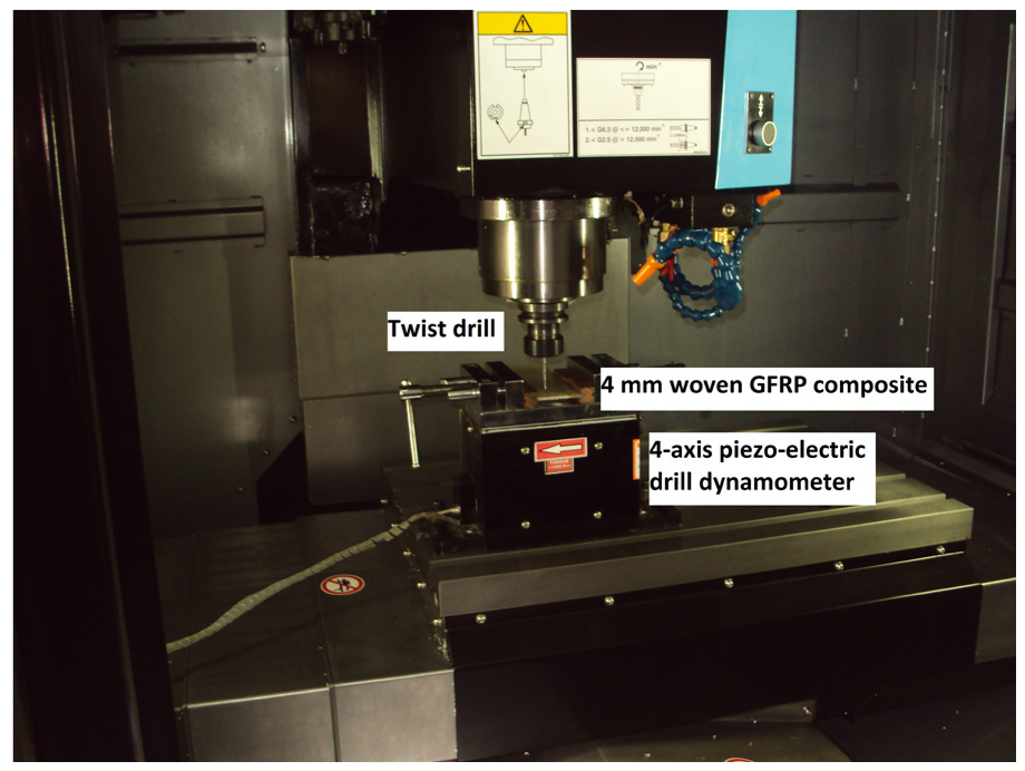
Experimental set-up (Hurco-VMX24Mi VMC) used for drilling in 4 mm woven GFRP composite laminate.
Mathematical modeling of drilling
Control systems are often analyzed using standard inputs such as step input (single and dual), ramp input and sinusoidal input. This is because the system’s response to any arbitrary input can be estimated from its response to these standard inputs. Unit step input is easy to generate, and it provides useful information on both transient and steady response characteristics of the system. In this work, drilling in GFRP composites is modeled as a single-input-single-output (SISO) system.
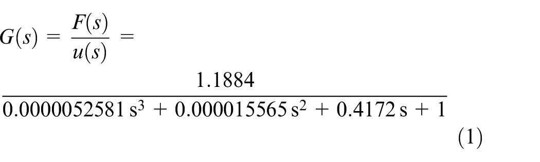
Dynamics of the drilling process in the composite laminate is modeled as a third-order transfer function between thrust force and feed-rate. Woven GFRP laminate of 4 mm thickness is drilled by giving a step feed-rate of 212.8 mm/min. Thrust force response obtained during experiment from the dynamometer is shown in Figure 2. Third-order transfer function G in s-domain between thrust force F and feed-rate u is extracted from this experimental time response of thrust force, using System Identification tool-box of MATLAB (equation (1))
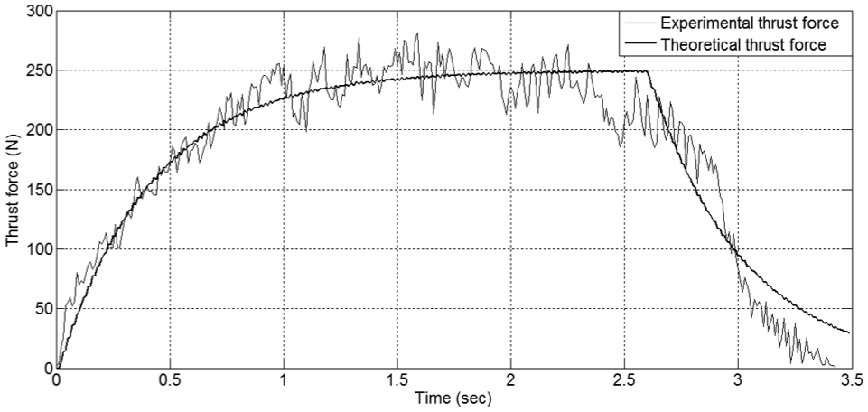
Experimental and theoretical thrust force during a drilling operation, at feed-rate of 212.8 mm/min.
As it is evident in Figure 2, good match exists between experimental and theoretical (using equation (1)) time response of thrust force, corresponding to step feed input of 212.8 mm/min. The transfer function in equation (1) is converted from s-domain to third-order differential equation in time-domain using inverse Laplace transform as
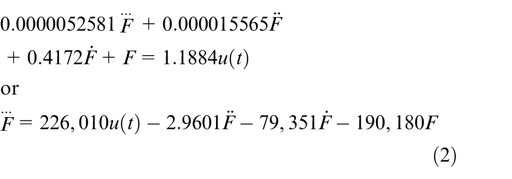
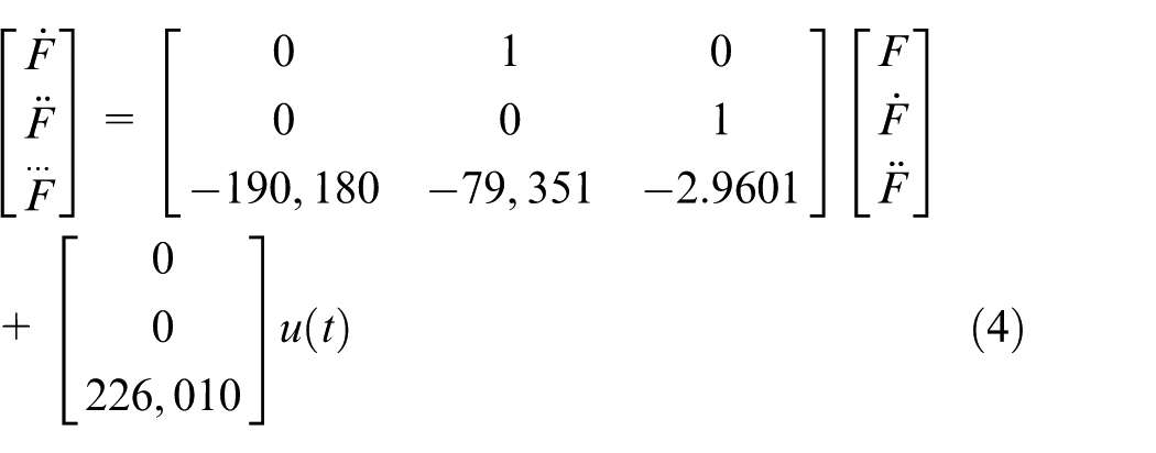
This third-order system is converted into a system of simple first-order differential equations in state-space (time-domain) as

where Ac is the continuous (3 × 3) system state matrix, X is the (3 × 1) state variable (containing thrust force and its derivative terms) vector, Bc is the continuous (3 × 1) input control vector, u is the (1 × 1) input vector (feed-rate) and t is the time. This model between thrust force and feed-rate can be further expressed as
For designing the controller in digital state-space, it is necessary to convert the continuous time model in state-space to a discrete equivalent using an A/D converter. This discrete model is capable of predicting output at each sampling instant k. Input to A/D convertor is a continuous time function u(t) for time t ≥ 0, and output consists of sequence of real numbers u(k), where k = 0, 1, 2, … with relation u(k) = u(t = kT); kT ≤ t < (k + 1)T, where T is the time interval between samples. Sampling rate is kept at 100 samples/s for the drilling process in this work. Zero-order hold retains the sample value during the sample interval T. Using this conversion, equation (4) is converted into a system of three coupled algebraic equations in discrete state-space as

where A is the discrete (3 × 3) system state matrix, X is the (3 × 1) state variable (containing thrust force and its derivative terms) vector, B is the discrete (3 × 1) input control vector, u is the (1 × 1) input vector (feed-rate) and k is the discrete time instant. For this work, the model between thrust force and feed-rate in discrete state-space is formulated using equation (4) as
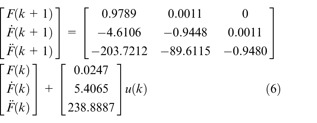
The presented state-space model representing drilling in composite laminates is controllable as its controllability matrix has full rank (rank = 3). Equation (6) is solved to obtain response of thrust force at different feed-rates.45–47
Control law for optimal tracking of critical thrust force
Thrust force is taken as output from the system model as shown in equation (7)
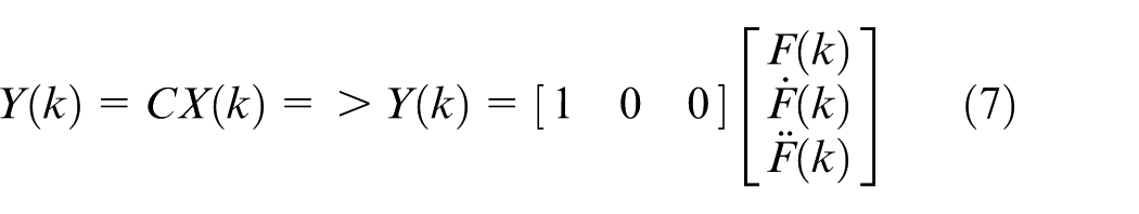
where Y(k) is the thrust force signal, and C is the output vector. Initial thrust force is taken as

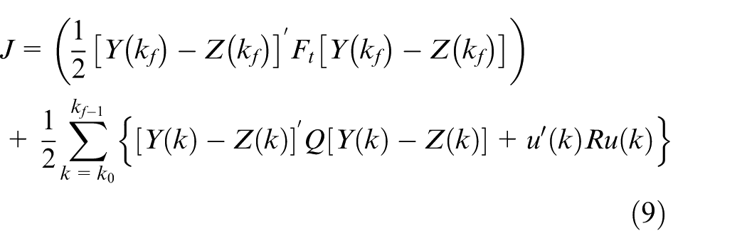
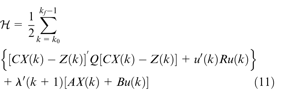
The dynamic system is controlled toward target reference signal profile Z(k) by minimizing a performance index (equation (9)) which is a quadratic cost functional involving quadratic of error and control effort. The performance index contains deviations in final state (terminal state), error between desired and actual output and the control effort. It is a quadratic function of state vector X(k) and is expressed as
where
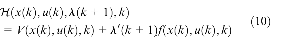
where V is a function consisting of performance index to be minimized subject to a constraining function f which is the state equation of the system. Usage of appropriate Lagrange multiplying vector
Optimal state is obtained by partial differentiation of equation (11) with respect to co-state at a discrete instant (k + 1). Optimal co-state is obtained from the Euler-Lagrange equation at optimal state.
48
Control equation giving optimization of performance index with respect to the control
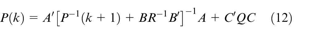
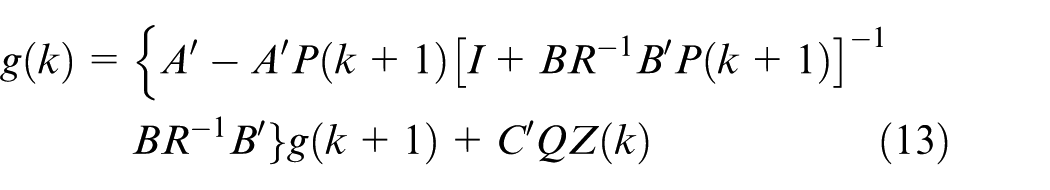
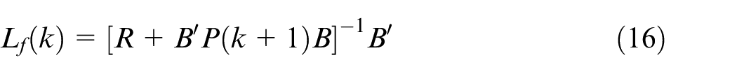
where

where

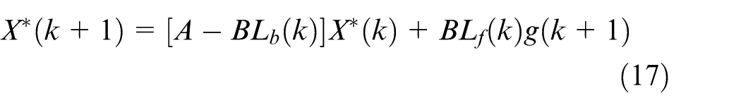
Block diagram of the optimal controller, based on equations (3) and (14), is given in Figure 3.
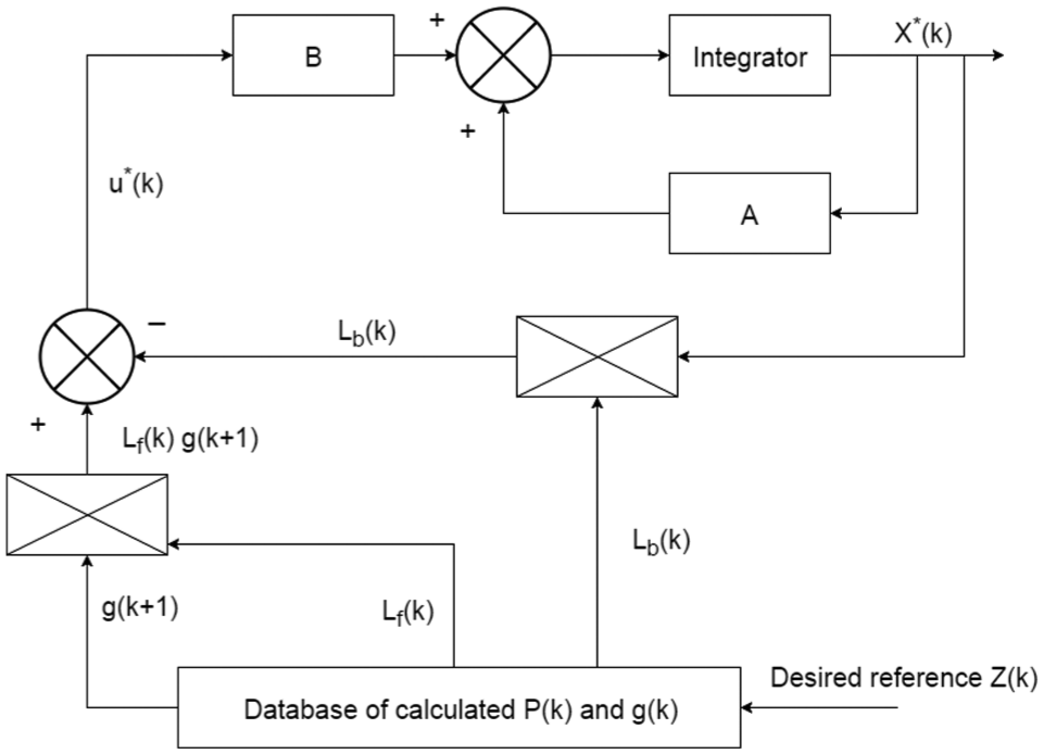
Block diagram of the optimal controller.
Feedback
Experimental validation of the control strategy
Critical thrust force is calculated using LEFM theory (equations (18) and (19)) as a function of composite laminate thickness, Young’s modulus, Poisson’s ratio and critical crack propagation energy release rate6,12,32
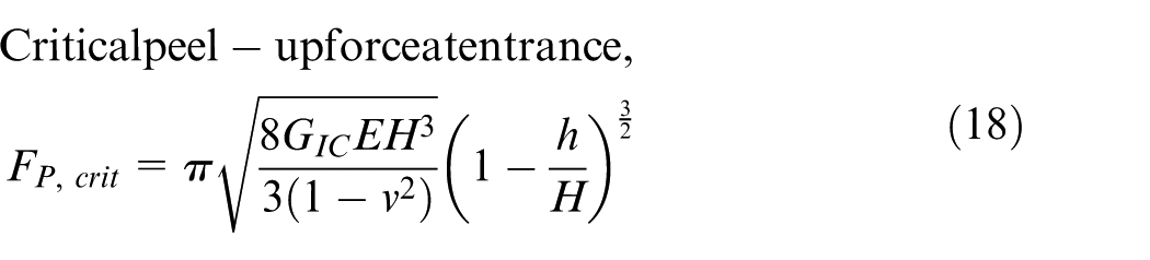
where GIC is the critical energy release rate for delamination in J/m2 (mode-I fracture), E is the modulus of elasticity in GPa, ν is Poisson’s ratio, h is the depth of the uncut material under the drill in meters and H is the thickness of the composite laminate in meters. Figure 4 shows the LEFM-based critical thrust force curve used as reference in proposed neural network controller. 32 Critical thrust force curve has not been fully exploited by the controller as can be seen in Figure 4. Reference thrust force provided for the neural network controller is kept constant at around 400 N. Therefore, drilling in the composite laminate takes place at almost constant feed-rate. There is no work available in literature wherein critical thrust force curve is fully tracked during drilling in composite laminates thereby avoiding delamination and resulting in better productivity.
LEFM-based critical thrust force curve for no delamination. 32
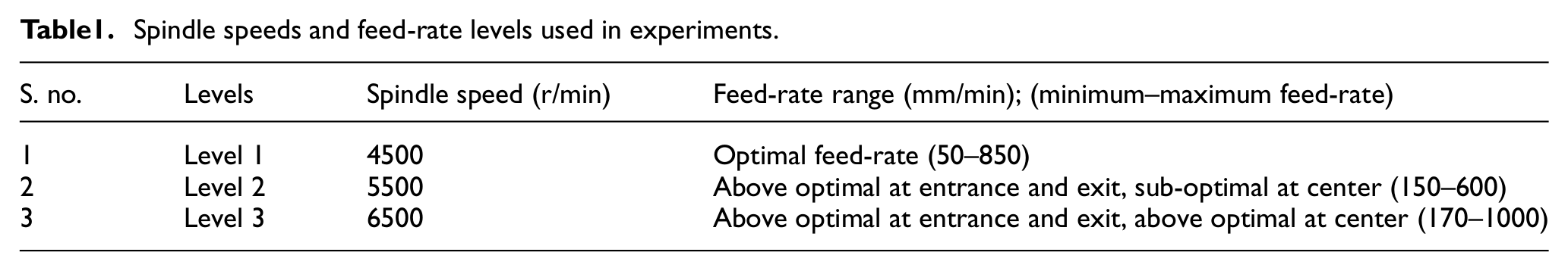
In this work, critical thrust force is calculated based on LEFM using equations (18) and (19) and used as reference Z(k) in the optimal controller. For 4-mm-thick woven GFRP composite laminate, the critical energy release rate for delamination (mode-1 fracture) GIC is 207 J/m2, modulus of elasticity E is 18.1 GPa and Poisson’s ratio ν is 0.19. As shown in Figure 5, effective tracking occurs when the error weightage in Q matrix is at position (1, 1), that is, Q11 is kept at 10,000 and control weightage R is kept at 0.1 (see equation (11)). Output thrust force tracked by optimal controller is overlapping the reference thrust force for most of the time. Optimal controller gives optimal feed-rate profile as shown in Figure 6 corresponding to the critical thrust force given in Figure 5. Thus, if the composite laminate is drilled at this feed-rate profile, it would be free from damage due to delamination at entry and exit. Higher feed-rates toward the center of laminate thickness makes drilling process faster resulting in better productivity without causing delamination in the composite laminate. Continuous feed-rate profile can be approximated as a sequence of several transient constant feed-rates as shown in Figure 7. This sequence of several transient constant feed-rates can be easily executed through programming on a CNC drilling machine. As shown in Figure 8, three levels are considered. In Level 1, feed-rate during drilling corresponds to optimal profile given in Figure 6 and executes as a sequence of constant feed-rates. In Level 2, feed-rate is as per sub-critical thrust force when drill bit is in the middle of the workpiece, while it is as per above critical thrust force at entry and exit. In Level 3, feed-rate is well above the feed-rate corresponding to critical thrust force throughout drilling in composite laminate. Optimal feed-rate (Level 1, varying between 50 and 850 mm/min) given by the controller is approximated and implemented in steps of 0.05 s as shown in Figure 7. Feed-rate at entry is kept minimum and increased after every 0.05 s to the maximum value when about 2 mm (half thickness) of workpiece is drilled. After drilling 2 mm depth, the feed-rate is reduced after every 0.05 s to the minimum value when about 4 mm of workpiece is drilled. Feed-rates thus remain at lowest at entry and exit during drilling in composite laminate. Higher feed-rates are used for drilling toward the middle of the composite. Level 2 feed-rate profile has feed-rate steps (varying between 150 and 600 mm/min) higher than optimal feed-rate at entry and exit of composite laminate. Feed-rate during drilling in the middle is kept sub-optimal to see its effect on delamination. In Level 3 profile, feed-rate steps (varying between 170 and 1000 mm/min) are well above optimal feed-rate throughout the drilling operation. Full factorial technique of experimental design is used, and nine experiments of drilling in 4-mm-thick woven GFRP composite laminate, using all three feed-rate levels, are conducted at three different spindle speeds of 4500, 5500 and 6500 r/min as shown in Table 1.
Tracking of critical thrust force reference trajectory by optimal controller while drilling 4-mm-thick woven GFRP composite laminate.
Feed-rate profile given by optimal controller corresponding to critical thrust force reference, for 4-mm-thick woven GFRP composite laminate.
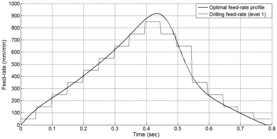
Drilling feed-rates corresponding to optimal feed-rate profile provided by controller for 4-mm-thick woven GFRP composite laminate.
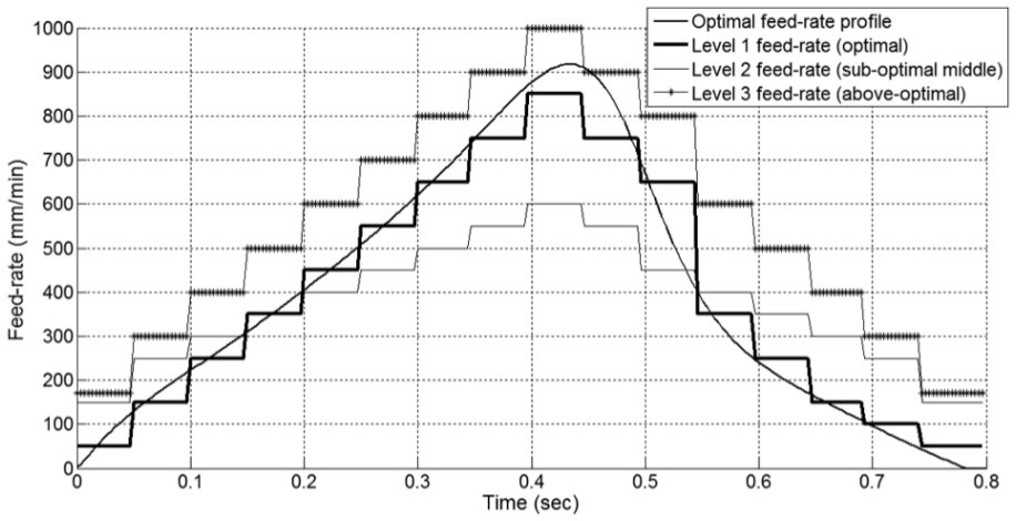
Various drilling feed-rate levels near optimal feed-rate used for drilling in 4-mm-thick woven GFRP composite laminate.
Spindle speeds and feed-rate levels used in experiments.
Results and discussions
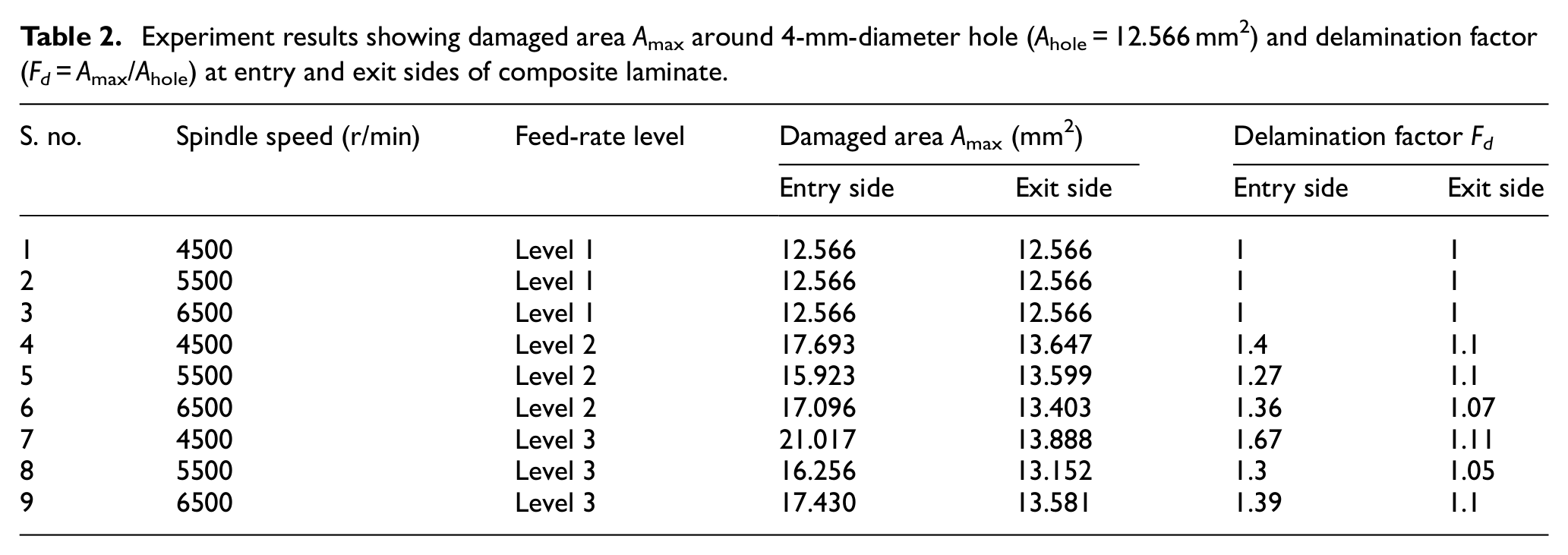
In the present experimental validation, it is found that when composite laminates are drilled using optimal feed-rates (Level 1) at all three levels of spindle speeds 4500, 5500 and 6500 r/min, no delamination is observed either at entry or at exit side of the drilled hole (as shown in Figure 9). Clean-cut holes are produced establishing that if the critical thrust force is tracked and the corresponding variable feed-rate is used for making holes in laminated composites, drilling-induced delamination can be avoided. When the feed-rate profile is changed to Level 2 which uses higher than optimal feed-rates at entry and exit and lower than optimal feed-rates in the middle part of drilling, delamination is observed at both entry and exit of composite laminate as shown in Figure 10. Drilled holes are quantified for delamination using the delamination factor. Delamination factor (Fd) is the ratio of the damaged area (Amax) to the hole area (Ahole). Damaged area is obtained through image segmentation and processing the image using ImageJ 1.42 (by National Institutes of Health), a public domain software. Drawing a freehand curve covering damage area around hole marks the damaged area. With Level 3 feed-rates, consisting of higher than optimal feed-rate throughout the drilling, delamination again occurs at both entry and exit of drill on the composite laminate, as shown in Figure 11. The delamination factor calculated at all speed and feed-rate combinations is tabulated in Table 2. Delamination factor, as shown in Table 2, corresponding to Level 1 feed-rates is always equal to 1, at Level 2, and at Level 3 feed-rates, it is always greater than 1. When constant feed-rate is used during drilling in a PMC, delamination at exit of the composite is more pronounced than at the entry. In this work, delamination factor is more at the entry side than at the exit side when Level 2 and Level 3 feed-rates are used. Lesser delamination factor at the exit may be attributed to low feed-rates toward exit in the present experimentation, which produce low thrust forces resulting in less damage due to delamination. Thus, it is proved experimentally that delamination-free holes can be drilled in a composite laminate if thrust force during the drilling operation is either equal or less than critical thrust force. If thrust forces during the drilling operation are above critical thrust force values, then damage due to delamination occurs in the workpiece. Strategy presented here can be exploited for drilling delamination-free clean-cut holes in composite laminates, using a conventional CNC machine.
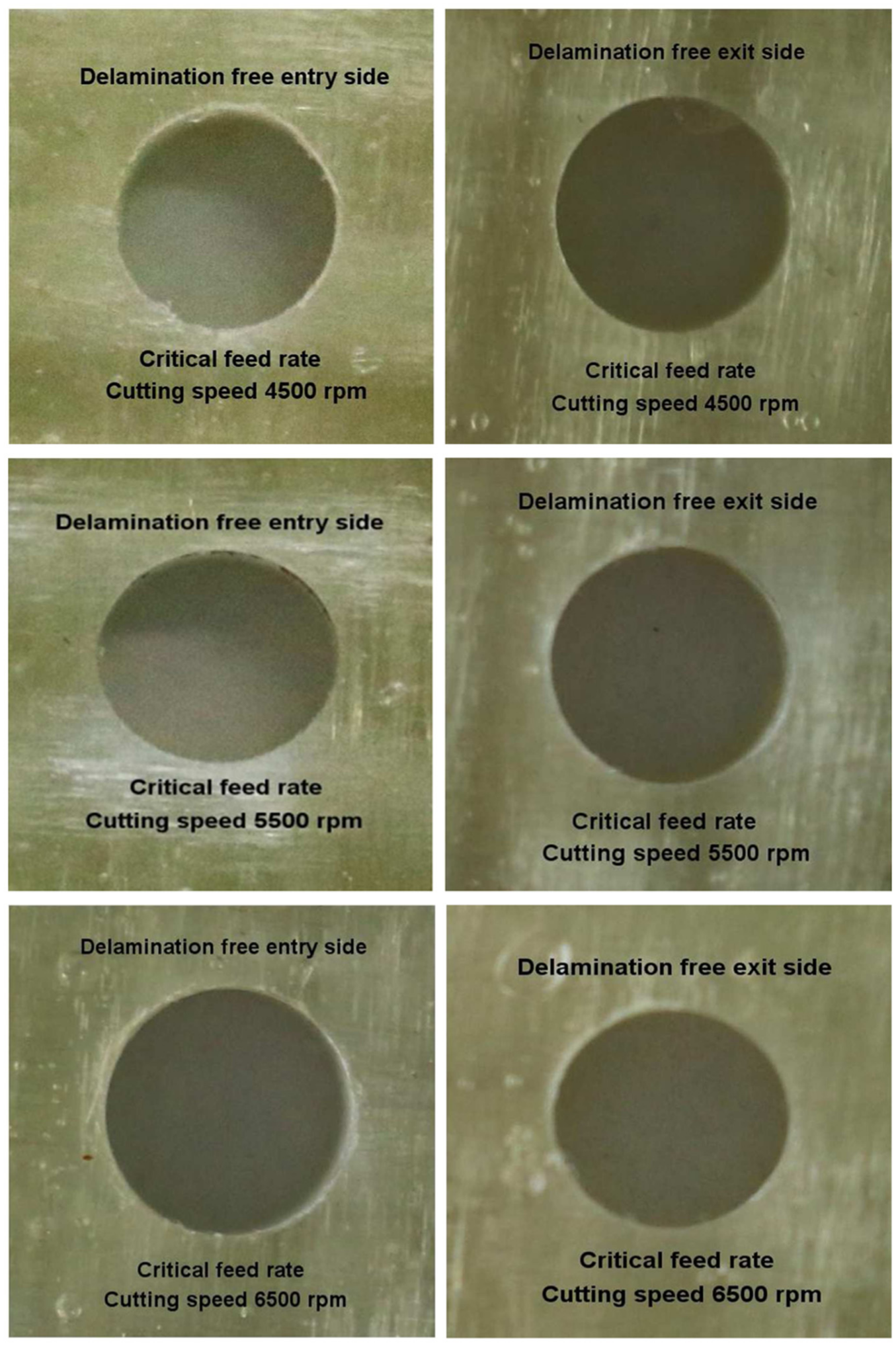
Delamination-free drilling of 4-mm-thick woven GFRP composite drilled using optimal feed-rate (Level 1) at cutting speeds of 4500, 5500 and 6500 r/min.
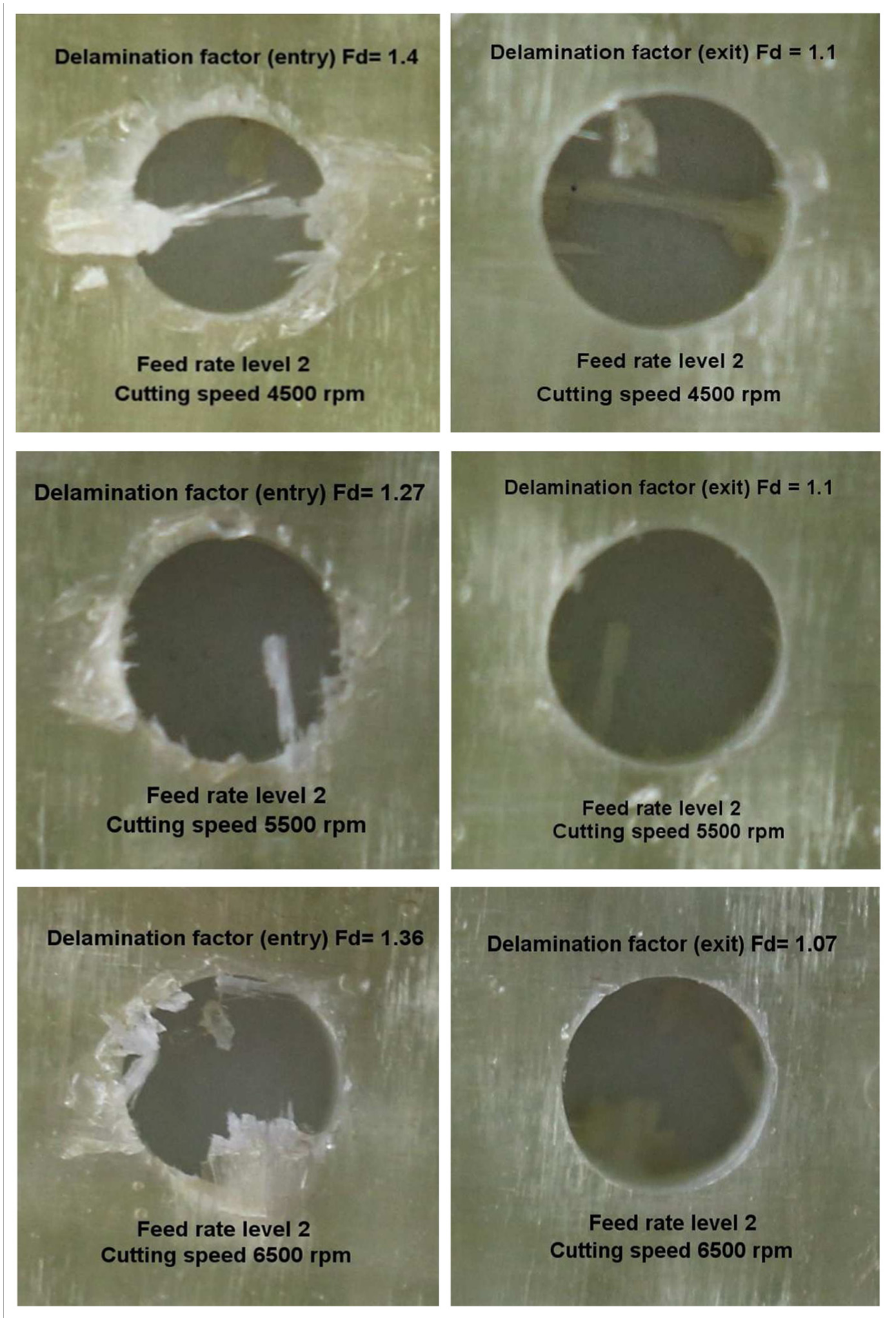
Delamination at entry and exit sides of 4-mm-thick woven GFRP composite drilled using Level 2 feed-rate at cutting speeds of 4500, 5500 and 6500 r/min.
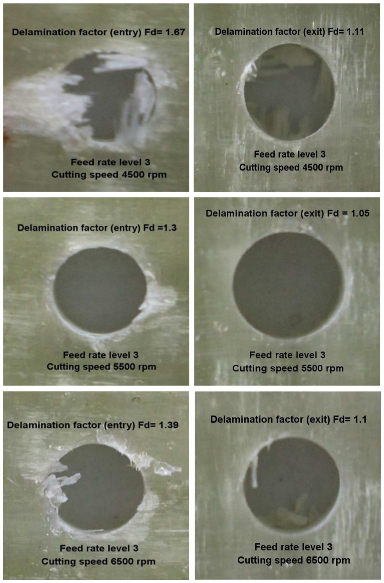
Delamination at entry and exit sides of 4-mm-thick woven GFRP composite drilled using Level 3 feed-rate at cutting speeds of 4500, 5500 and 6500 r/min.
Experiment results showing damaged area Amax around 4-mm-diameter hole (Ahole = 12.566 mm2) and delamination factor (Fd = Amax/Ahole) at entry and exit sides of composite laminate.
Conclusion
In the present experimental endeavor, a control strategy based on tracking the critical thrust force reference profile by optimal controller is proposed for delamination-free drilling in composite laminates. Output from optimal controller is an optimized feed-rate profile obtained by tracking the critical thrust force reference profile. Experimental validation of the proposed strategy is performed, and results indicate that drilling using optimal feed-rate profile produces delamination-free holes in composite laminates. The following salient points are concluded from this research work:
When critical thrust force is used as reference in the optimal controller, optimal feed-rate profile is obtained. Drilling in the composite laminate, by following this optimal feed-rate profile, does not produce damage due to delamination at both entry and exit sides of the drilled hole.
Using optimal feed-rates results in better productivity due to faster drilling.
Using feed-rates more than optimal feed-rate profile causes delamination at entry and exit of composite laminate during drilling. This verifies that if the critical thrust force is exceeded during drilling, delamination is bound to take place.
When more optimal feed-rates are used throughout the drilling operation, delamination occurs at both entry and exit of the composite laminate.
Optimal feed-rate curve for delamination-free drilling in composite laminates can be easily implemented as a sequence of several small constant feed-rate steps through programming on a CNC machine.
This work explicitly presents a procedure for obtaining delamination-free clean-cut holes in composites, using a conventional CNC machine.
Footnotes
Declaration of conflicting interests
The author(s) declared no potential conflicts of interest with respect to the research, authorship and/or publication of this article.
Funding
The author(s) disclosed receipt of the following financial support for the research, authorship, and/or publication of this article: This work was supported by the TEQIP-II grant (NPIU/TEQIP-II/FIN/31/623) of MHRD, Government of India.