
Abstract
The application of modeling theories and the choice of failure criteria are difficult in part because they are too varied and must be validated by biaxial tests, which are expensive to be performed. This article is devoted to the nonlinear modeling and failure criteria which are employed in the design and analysis of anisotropic materials. Indeed, in this work, a study of the macroscopic and microscopic behavior of a graphite epoxy under a three-point bending test is conducted, and the successive failures are also predicted. Experimentally, the damage progression and the effect of geometrical parameters are followed and identified in detail. The analytical modeling is based on a recently developed approximation for isotropic materials. This approximation is also valid for the studied quasi-isotropic laminated composite. A software program has been elaborated for the application of the most general failure criteria. The results obtained by this analytical modeling show a good correlation with those of the experimental study.
Introduction
A large formalism of failure criteria has been developed to describe the failure envelopes of the materials. Whereas, the laminated composites reinforced with unidirectional fibers and fabrics show a great variety of the failure behaviors. Consequently, the choice of failure criteria is difficult because they are too varied and must be validated by extremely complex biaxial tests. 1 In general, the material properties are usually considered at the macroscale level via material homogenization. Indeed, the microscopic investigations require the modeling of fiber/matrix interfaces. This leads to extremely deep computations. The follow-up of the failure initiation in laminated composite structures is a very challenging task, and prediction of the failure is far from being totally solved.
The orthotropic material strength parameters are typically established by a test prediction in the direction of the principal material. Generally, beams and plates are easily subjected to in-plane multiaxial stress states during service. This stress depends on the stacking sequence and the physical properties of the mixture of resins and fibers. It should be noted that, the in-plane shear stress may play a significant role in the failure. 2,3 Consequently, a number of failure criteria have been developed in order to predict the failure loads under arbitrary stress states. These criteria can be grouped into two main groups.
Failure criteria neglecting the interactions between different stress components. Failure criteria taking into account the interactions between different stress components.
In our case, both types are used, and we also include in our study the recently published failure criteria.
The three-point bending test is a useful and simple experiment often used to determine the mechanical properties and failure criteria of laminated composite. Many authors have been interested in this test,
4
-6
but the damage progression has not been studied in detail. In this work, we use and improve the experimental results developed by Echaabi et al.
7
For this purpose, two stacking sequences of a woven carbon T700/epoxy laminate ([45/0]
Irhirane et al. 8,9 used the limited reduction model combined with failure criteria. This approach predicts the failure modes and macroscopic failure in the linear behavior only. A nonlinear behavior observed in other specimens has not been studied and is still difficult to resolve. In this respect, in part of our work, we focus on modeling the behavior of specimens with a nonlinear response.
Chowdhury et al.
10
performed several four-point bending tests on a typical stacking sequence used in composite structures [45/0/45/90]
For theoretical modeling, an approximate theory, developed by Venetis and Sideridis, 11 is employed. It correctly describes the nonlinear center-deflection of three-point bending specimens using a simplified formalism of two equations. 12 These analytical methods are combined with various failure criteria, and the results are compared with the experimental results.
Experimental setup
Material
The used material is a prepreg of carbon (type taffeta fabric T700) and epoxy (Figure 1). The material properties are presented in Table 1. 13
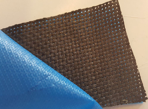
Prepreg carbon/epoxy used.
Mechanical properties of prepreg carbon T700/epoxy at 25°C.

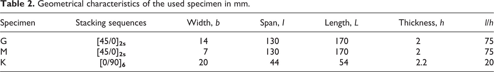
Specimen
The specimen layup consists of two different stacking sequences given by [45/0]
Geometrical characteristics of the used specimen in mm.
A plate made of the prepreg material is cured in an oven at 120°C for 60 min with a ramp up rate of 2°C min−1. Care is taken to ensure that the fiber directions are aligned correctly (Figure 2).
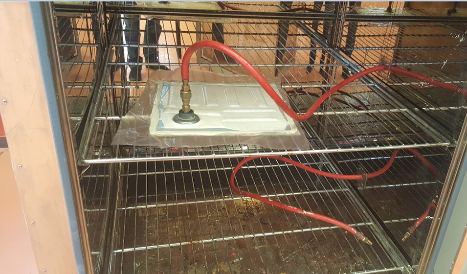
Vacuum bagging process.
Cutting and polishing
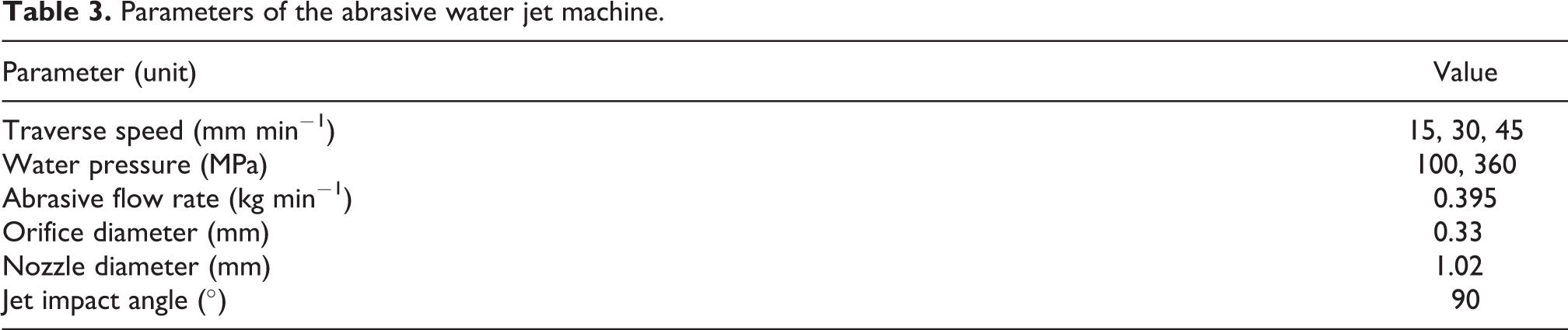
The specimens are machined from the cured plate using abrasive water jet cutting (Figure 3). The operating parameters are given in Table 3.

Cutting a laminate plate using the abrasive water jet machine.
Parameters of the abrasive water jet machine.
The final machining of the specimen sides is performed using abrasive sandpaper (P360, P600, and P1200) and alumina powder of 0.3 µm (Figure 4) to minimize damage caused by the cutting process.

Composite polishing machine.
Three-point bending machine and microscope
The three-point bending machine, shown in Figures 5 and 6, is used to evaluate the mechanical behavior of the specimens. This machine equipped with 5-kN force cell with an electromechanical cylinder of 100 mm of stroke ensures the application of the loads; it is equipped with a gauge force sensor and a displacement sensor to measure the deformation under load of the specimens. An asynchronous motor driven by a frequency converter actuates the cylinder; the load–displacement curves are recorded using a PC connected to the machine using the software Quant X (version 6 - Revision 6014) to save and analyze the results according to the ASTM specification. 14 Moreover, a digital microscope monitors the damage and the final failure of the specimens. This microscope includes a digital camera with a USB output and software for acquiring the data. Finally, the parameters of this instrument are listed in Table 4.

Three-point bending machine.
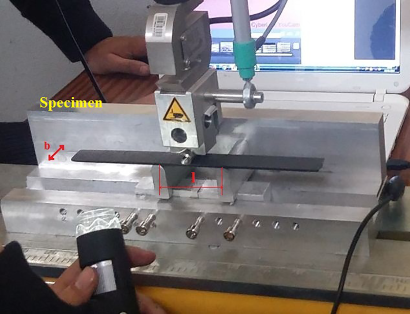
Three-point bending test.
Parameters of the digital microscope.

Test procedure
A total of five specimens for each stacking sequence [45/0]
Analytical analysis
Law of behavior of a laminate
For laminated composite beams, the constitutive relation can be expressed as follows 15

where
Equivalent longitudinal elastic modulus
The general law of the laminate determines the law of membrane behavior

It is possible to replace the force flows Nx , Ny , and Txy by average global stresses. Then, we deduce from equation (1) the law of laminate membrane behavior made “homogeneous” as

The terms of the matrix

The ratios

Knowing that the longitudinal elastic modulus

Approximate solution to the three-point bending equation for a simply supported beam
The nonlinearity observed for the high values of the thickness ratio l/h is mainly generated by the lateral component of the reaction X′ (Figure 4). Indeed, this component depends on α, which is the angle of rotation of the midplane with respect to the y-axis at the supports. This normal force of compression X′ tends to emphasize the deflection by deforming the beam in a direction perpendicular to the compression axis. However, for a small deflection or a small l/h ratio, the angle α is still low, and the reactions can be considered as perpendicular to the beam. This leads to a linear behavior. The work of Venetis and Sideridis 11 consists of introducing this buckling effect into an analytical model. By studying the equilibrium of a beam subjected to the three-point bending (Figure 7), the authors developed two main equations (7a) and (7b) giving the center-deflection w c and the corresponding load P as a function of the angle α and two integrals that are approximately solved. Thus, they come up with a final model reduced to two equations (8) and (9), and easy to apply

Beam in the deformed state.

and

where α is the angle of rotation of the midplane with respect to the y-axis at the supports, E is the equivalent longitudinal elastic modulus, and I is the quadratic moment along the y-axis.
According to the theory of Werren and Norris,
16
the studied laminate whose layer sequence is [45/0]


In our study,
Failure criteria for composite layered structures
Maximum stress criterion
The failure criteria, when neglecting the interactions between the different stress components, are the simplest and usually propose one inequality for each one of the three in-plane stress (or strain) components. The maximum stress criteria belong to this category. 1
If the fibers are taken parallel to axis 1 and the main referential of the material is considered, then the failure conditions can be stated as follows 1


Figure 8 shows an example of the failure envelope of the maximum stress criterion. This envelope is obtained by neglecting the shear–stress interaction and the linear transformation using the Hooke matrix. In practice, this mathematical relation cannot be rigorously satisfied.

Failure envelope of the maximum stress criterion.
Maximum strain criterion
The same approach as for the maximum stress criterion is followed to obtain the maximum strain criterion. So, we consider the corresponding strains in the failure conditions as follows 1


Tsai–Hill criterion
Tsai–Hill is an interactive criterion that takes into account the effect of the in-plane shear stress. 1 This failure criterion is formulated with reference to the distortion energy. Thereby, the failure condition is given by the following inequality

where the failure parameters X and Y depend on the considered quadrant of the coordinate plane, and are

Figure 9 shows an example of the corresponding failure envelopes for different
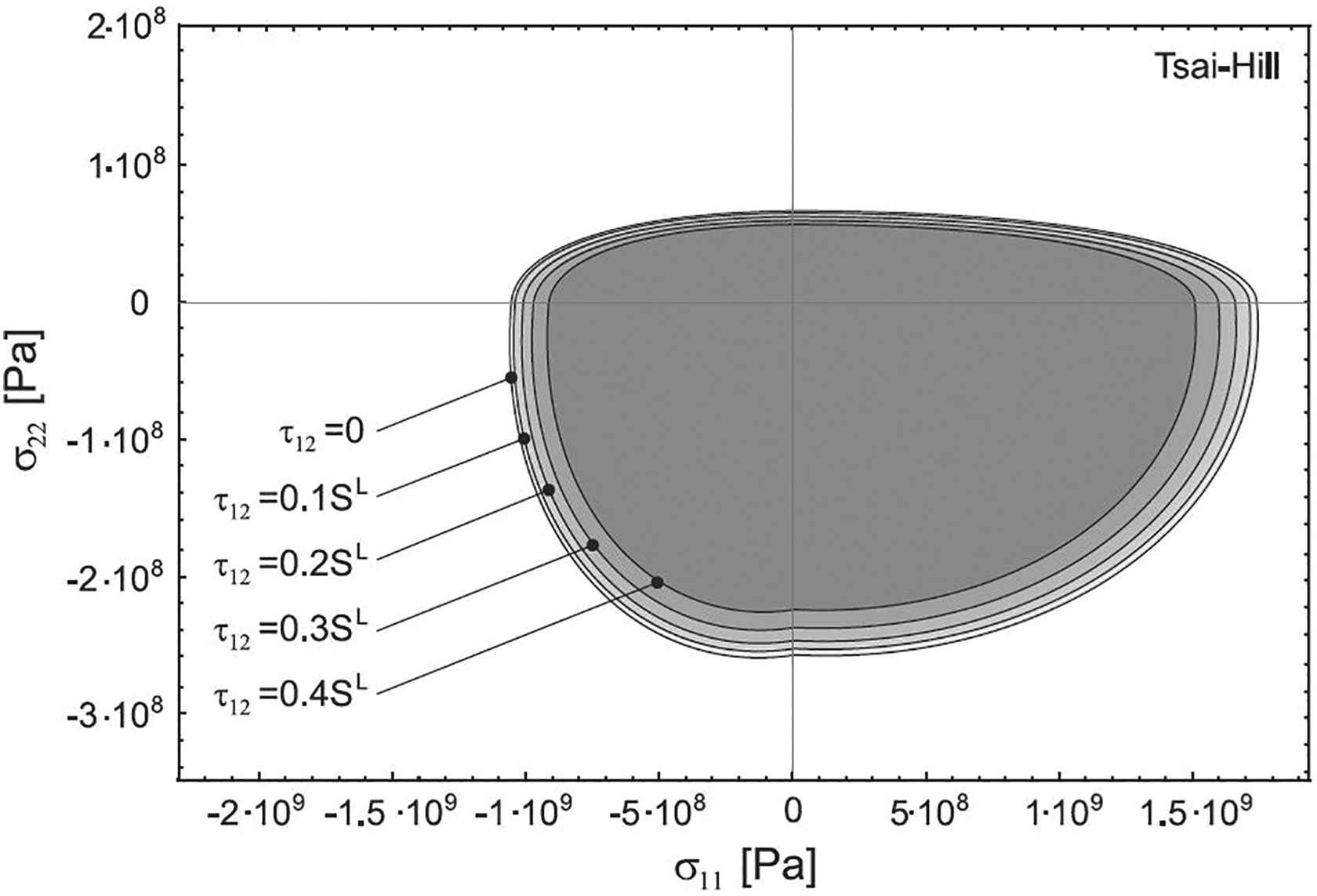
Failure envelopes of the Tsai–Hill criterion by varying
Tsai–Wu criterion
Tsai–Wu criterion is an interactive approach considering the in-plane shear stress effects. This failure criterion is formulated in order to match the experimental results. In addition, it is not derived from a physical basis

Like the result of the Tsai–Hill criterion, the semimajor and semiminor axes of the corresponding ellipses are reduced by the in-plane shear stress effect (Figure 10).

Failure envelopes of the Tsai–Wu criterion by varying
Hashin criterion
Four interactive and noninteractive conditions are proposed by the Hashin criterion, in order to differentiate matrix and fiber failures caused by tension or compression. Sun et al. 17 proposed a further version based on some empirical modifications. Consequently, the Hashin criterion is interactive, and the failure conditions are given by the following inequalities.
Fiber failure for tension (σ 11 ≥ 0)

Matrix failure for tension (σ 22 < 0)

Matrix failure for compression (σ 22 ≥ 0)

Fiber failure for compression (σ 11 < 0)

LaRC03 criterion
The LaRC03 failure criterion suggests a combination of five interactive conditions in order to indicate a crack initiation in the matrix or a failure due to fiber compression. This failure criterion was developed after the World-Wide Failure Exercise (WWFE) at the Langley Research Center. 1,18 A noninteractive inequality is suggested only for the tensional fiber failure. Thereby, a summary of the LaRC03 criterion is proposed in the following equation.
Matrix cracking for tension (σ 22 ≥ 0)


Matrix cracking for compression (σ 11 < 0)

Where the effective shear stresses

Fiber failure for tension (σ 11 ≥ 0)

Fiber failure for compression (σ 22 < 0)

Usually, α 0 = 53° from test data 1,18 (see Figure 11).

Angle of the fracture plane of a unidirectional lamina subjected to transverse compression and in-plane shear.
The Hashin criterion indicates that the resizing occurs relative to a point located along the edge of the envelope pertaining to the fiber compression. Moreover, the LaRC03 criterion shows that the resizing center is a point at the edge of the envelope related to the fiber failure due to traction (Figures 12 and 13).

Failure envelopes of the LaRC03 criterion by varying

Failure envelopes of the Hashin criterion by varying
In the next section, we test, in the case of the three-point bending test, the maximum stress criterion for its simplicity of application. We also use the Tsai–Hill and Tsai–Wu criteria to take into account the effect of the in-plane shear stress and because these interactive criteria are widely used in computer codes. We apply the Hashin and LaRC03 criteria to predict the observed failure mode.
Generally, these two-dimensional criteria remain valid for all thin composite layered structures. In addition, all stacking sequences are valid, except those that cause delamination.
Results and discussion
Experimental results
Effect of the thickness ratio l/h
To study the influence of the thickness ratio l/h, on the behavior of the specimens, two different values of l/h are treated (see Table 2). We test each specimen (M, G, and K) five times according to the ASTM specification. Therefore, the macroscopic load–displacement curve of each specimen is presented. The first result of this experimental study illustrates that the specimens with a large thickness ratio l/h (M and G) have a nonlinear behavior (Figure 14(a)) and the specimen with a small ratio (K) exhibits a linear behavior (Figure 14(b)). Figure 14(a) shows one macroscopic failure for specimens M and G. However, Figure 14(b) indicates three macroscopic failures for specimen K.
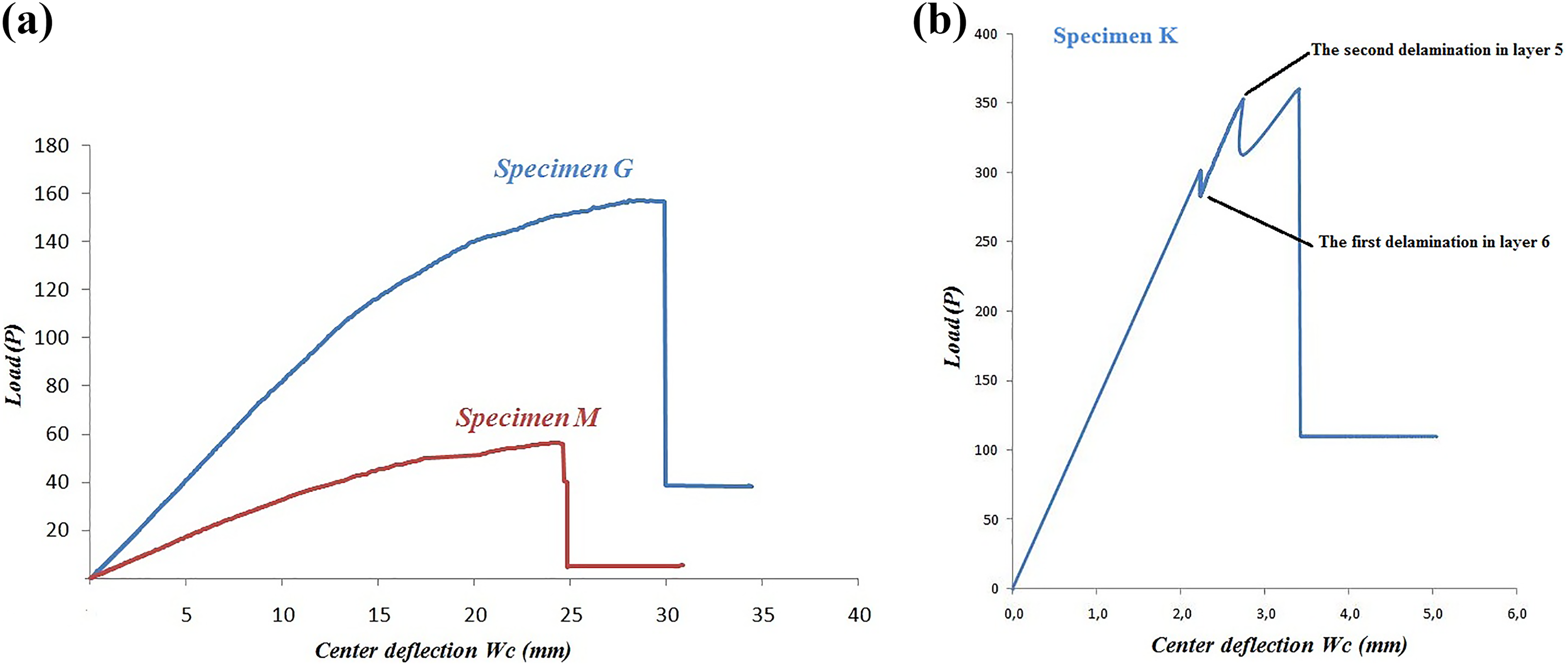
Experimental macroscopic curves of the test specimens: (a) G and M and (b) K.
Successive failures
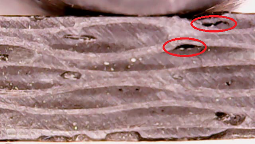
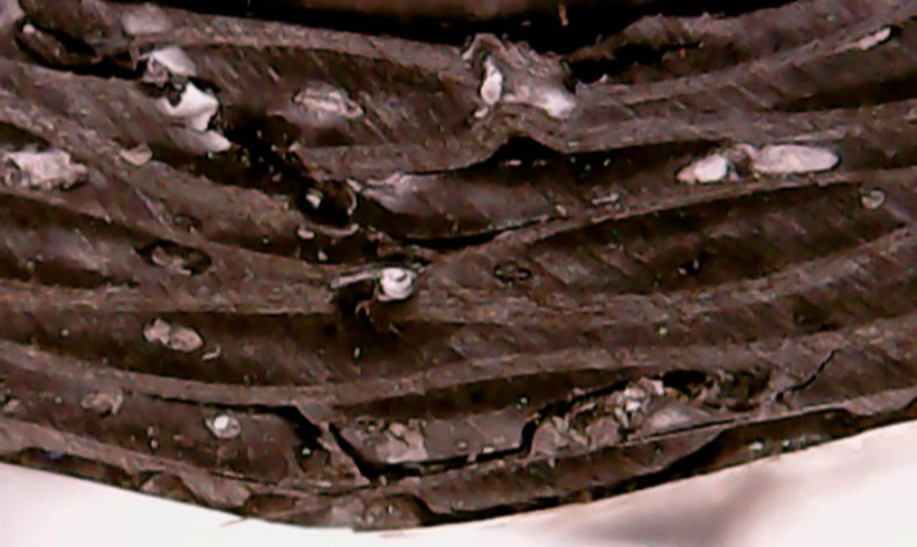
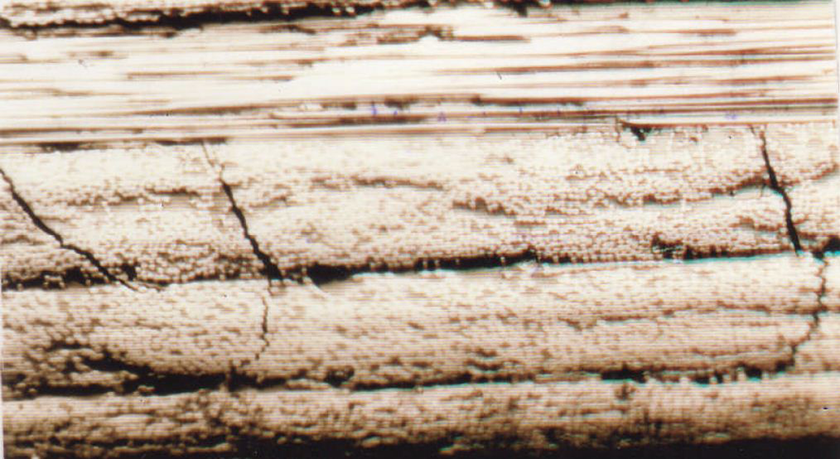
The experimental results obtained for specimen G are presented in Figures 15 to 18. The first microscopic failure of this specimen is observed in the weft of layer N°2 for a displacement of 19.08 mm (Figure 16). The second matrix cracking is detected in the weft of layer N°1 for a displacement of 20 mm (Figure 17). The next microscopic failure is found in the weft of layers 7 and 8 for a displacement of 21 mm. It grows to the weft of 45° layers up to the microscopic failure for a displacement of 26 mm (Figure 18). For specimen M, only the width b is modified and is equal to 7 mm. We use the same method to observe the succession of failures under the microscope. We find that specimen M exhibits a similar progression of the failure to that of specimen G.

The stacking sequence [45/0]

The first crack in the weft of layer 2 of the test specimen G loaded up to 136.25 N.

The second crack in the weft of layer 1 of the test specimen G loaded up to 140.32 N.

The final failure of the test specimen G loaded up to 156 N.
For specimen K, two successive failures are obtained, whereas for specimens G and M, only one macroscopic failure is observed. A low ratio l/h = 20 generates a normal stress to the average plane of the specimen. This leads to an intra-layer delamination “mode I” as illustrated in Figures 20 and 21. We also observe that the obtained damage mode for this specimen with stacking sequences [0/90]
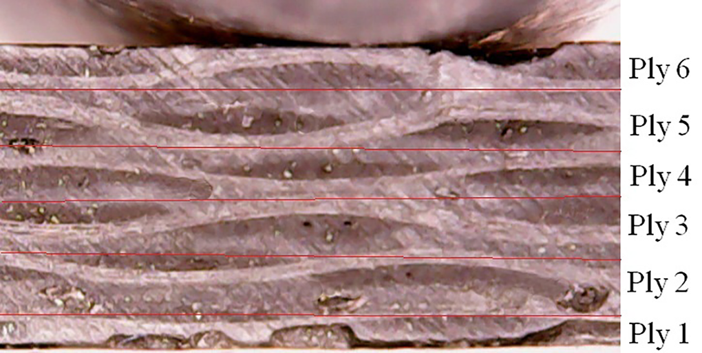
The stacking sequence [0/90]

The first micro-delamination in layer 6 of the test specimen K loaded up to 309 N.
The second delamination in layer 5 of the test specimen K loaded up to 353 N.

Progression of the delamination in the test specimen K.
The final failure of the test specimen K loaded up to 359 N.
Analytical results
Nonlinear modeling
The nonlinear analytical behavior of specimens G and M is modeled using the approach of Venetis and Sideridis 11 that was recently developed for isotropic materials (equations (8) and (9)). This model is also valid for studying the quasi-isotropic laminate composite.
Indeed, after substituting the equivalent longitudinal modulus E eq in equations (8) and (9), and resolving them, we deduce the value of the center-deflection, the applied load P, and the angle α. The obtained result shows a good correlation between the experimental and analytical curves for specimens G and M. This is shown in Figure 24. Using the same approach, we also model some preestablished experimental results in the literature (Figure 25). 12
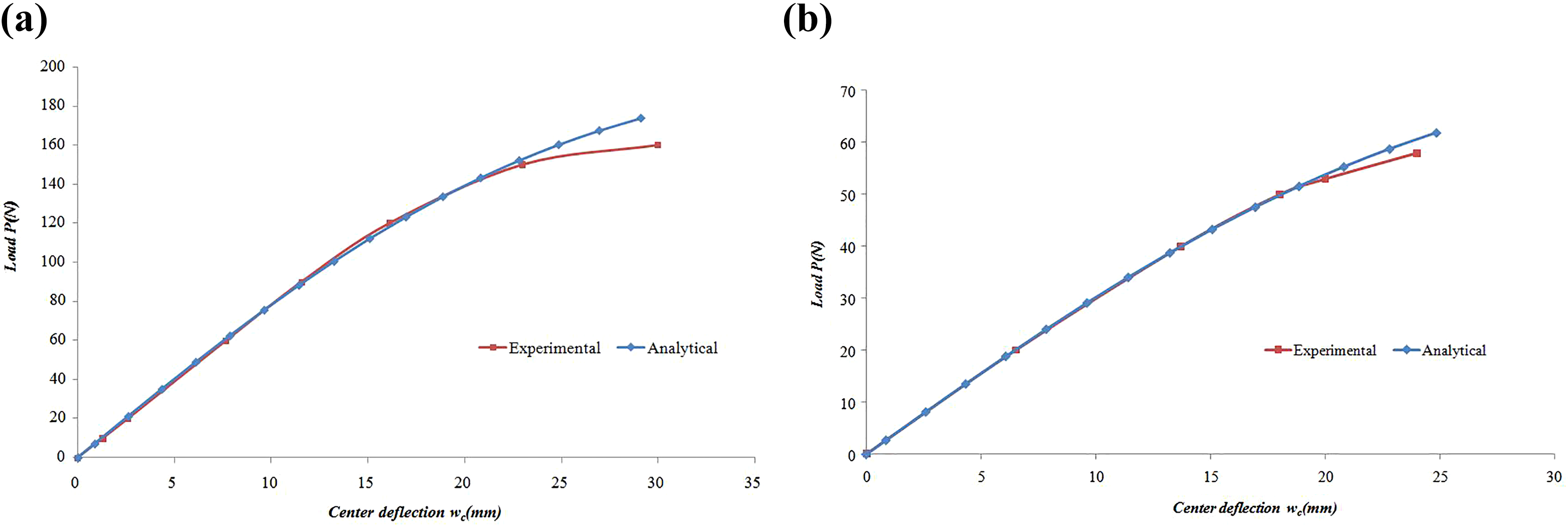
Analytical and experimental load–displacement curves of the test specimens G (a) and M (b).

Variation of the center-deflection w c according to the load P for specimens E (a) and F (b). 12
Simulation of the failure
After analyzing the experimental macroscopic curves of the test specimens G and M (Figure 14) where the matrix cracking is observed (Figures 16 and 17), we notice that the final failure occurs only when a fiber oriented 0° is damaged or damages the matrix of all layers. Figure 26 illustrates our methodology used for a progressive failure analysis. The failure theory algorithm is developed using VBA/Excel application. The deflection causing the damage allows the calculation of the applied load using the nonlinear approach of Venetis and Sideridis mentioned in “Approximate solution to the three-point bending equation for a simply supported beam” section.

Progressive failure algorithm.
To test the failure criteria cited in “Failure criteria for composite layered structures” section and our failure theory algorithm, we consider in a first step, a graphite–epoxy reinforced with unidirectional fibers with the stacking sequence [[+45/−45/90/0]
The dimensions of the specimens are listed in Table 5. Thus, the analytical results are combined with the criteria of the maximum stress, Hashin, LaRC03, and Tsai–Hill enable us to reduce the error margin to 6% compared to the experimental results. On the other hand, the Tsai–Wu criterion overestimates the failure. This is given in Tables 6 and 7.
Geometrical characteristics of the used specimen in mm.

Results obtained by analytical models for test specimen B.

MF: matrix failure; FF: fiber failure; MFT: matrix failure for tension; MFC: matrix failure for compression; MCT: matrix cracking for tension; MCC: matrix cracking for compression; FFT: fiber failure for tension.
Results obtained by analytical models for test specimen E.

MF: matrix failure; FF: fiber failure; MFT: matrix failure for tension; MFC: matrix failure for compression; MCT: matrix cracking for tension; MCC: matrix cracking for compression; FFT: fiber failure for tension.
In a second step, we model our fabric prepreg “carbon/epoxy” by analogy with a [0°/90°] laminate 22 (Figure 27). The obtained results are listed in Tables 8 to 12.

Modeling of a fabric using a [0°/90°] laminate.
Results obtained by the maximum stress criterion for test specimen G.

Results obtained by the Tsai–Hill criterion for test specimen G.

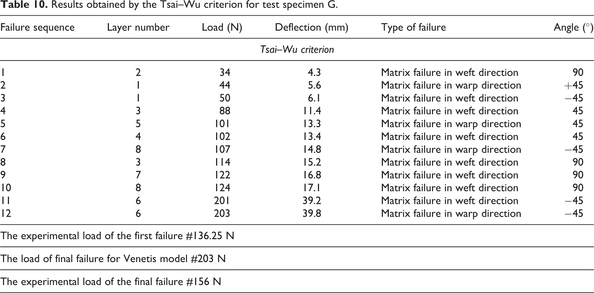
Results obtained by the Tsai–Wu criterion for test specimen G.
Results obtained by the Hashin criterion for test specimen G.

Results obtained by the LaRC03 criterion for test specimen G.
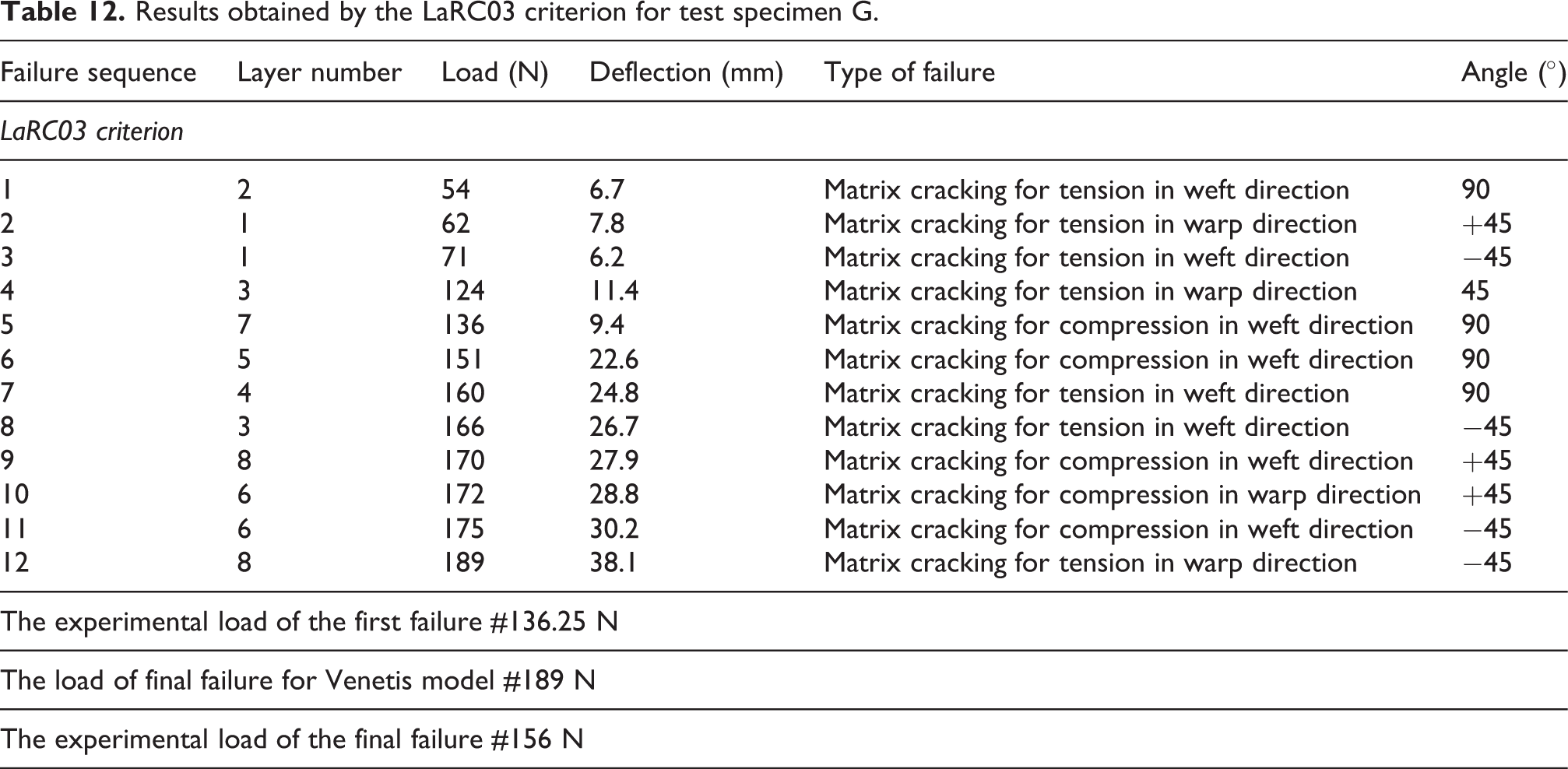
In the case of the fabric, we notice that the criterion overestimates the final failure compared to the experimental results, with an error margin of 35%. This large dispersion can be explained by the approximations imposed by the analogical method, which neglects the effect of interactions between warp and weft fibers 22 (Figure 28).

The interactions between warp and weft after loading.
To interpret the results given in Tables 6 to 12, we thoroughly analyze the angle of the fracture of the tested specimens (Figures 29 to 31).

Angle of the fracture related to specimen G—layer 2.

Angle of the fracture related to specimen G—layer 1.
Angle of the fracture related to specimen with the stacking sequence [[+45/−45/90/0]
We can notice, in the case of the three-point bending test, that the angle of the fracture related to the specimens is in the order of 53°. As mentioned in Puck’s work,
2
The matrix failures dominated by in-plane shear occur in a plane that is normal to the ply and parallel to the fibers (α = 0°). For increasing the amounts of transverse compression, the angle of the fracture plane a changes to about 40°, and increases with compression to 53°± 2° for pure transverse compression.
A study conducted by WWFE
2
shows that the failure criteria converge toward the same results in the case of

Comparison of failure envelopes and WWFE test data for unidirectional composite E-Glass/LY556.
Conclusion
Many authors
23
-26
have developed numerical and analytical approaches to link the state of the nonlinear behavior bending with the main characteristics of the specimens. These methods have a complexity of application with a large number of unknowns to be determined. Hence, we proposed a simple approximate approach which accurately describes the center-deflection of specimens in large deflection. The results obtained by these models predict the nonlinear experimental curves with good precision. Moreover, the prediction of the succession of the failure and the first macroscopic failure was well estimated by the maximum strain, Hashin, LaRC03, and Tsai–Hill criteria. Elsewhere, an experimental study of the behavior of carbon/epoxy woven laminates under a three-point bending test was done. This investigation confirmed the relationship between the thickness ratio l/h and the behavior of carbon/epoxy woven laminates where two values are treated (l/h = 70 and 20). The obtained results indicate that the specimens with a large thickness ratio l/h show a nonlinear behavior and those with a low thickness ratio l/h exhibit a linear behavior. The damage progression and the failure mode under static loading in three-point bending of two stacking sequences were presented. It was found that the successive failures depend on the thickness ratio l/h, but the width b has no influence on this ratio. Finally, the stacking sequence has an effect on the failure mode where the sequence [90/0]
Footnotes
Declaration of conflicting interests
The author(s) declared no potential conflicts of interest with respect to the research, authorship, and/or publication of this article.
Funding
The author(s) received no financial support for the research, authorship, and/or publication of this article.