



Abstract
Tidal kinetic energy is characterized by its bidirectional flow nature, which raises unique challenges for efficient power conversion. Conventional tidal current energy systems commonly employ horizontal-axis open-propeller turbines, often requiring additional mechanisms to accommodate changes in flow direction. This study presents the development of a theoretical analysis model aimed at improving the performance of a bidirectional ducted tidal turbine. A systematic design methodology for a bidirectional turbine rotor is proposed, emphasizing simplicity, mechanical reliability, and obedience to fundamental turbomachinery principles. The theoretical framework incorporates actuator disk theory to establish a performance reference, resulting in a maximum power coefficient of 0.385 based on the maximum duct area. This value is proposed as the ducted Betz limit for ducted tidal turbines. A model-scale experimental validation of the bidirectional duct–turbine system was conducted at a blockage ratio of 0.105. The experimental results yielded a maximum power coefficient of 0.093, which, although significantly lower than the theoretical limit, confirms the applicability of the proposed ducted Betz limit as a meaningful performance benchmark. The rotor design approach is based on Euler’s turbomachinery equation, ensuring consistency with angular momentum conservation principles. The integration of a duct allows for a reduction in turbine diameter for a given power output, potentially enhancing structural durability and reducing system costs. Overall, the proposed analytical framework and design methodology provide a structured basis for evaluating and optimizing the performance of bidirectional ducted tidal turbines.
Keywords
Introduction
Ocean energy is one of the renewable energies and the importance of utilizing it has been increasing year by year. Major four ocean energy sources are tidal, wave, temperature gradient, and salinity gradient, respectively. 1 Among these ocean energy sources, many researches and developments have been conducted for wave and tidal energy. As for wave energy, the wind over the surface of the ocean creates waves in many areas around globe, so wave energy contains huge technical potential of 29,500 TWh per year, 2 therefore, wave energy converters are researched such as Zhou et al.3,4 and Zhang et al. 5 As for tidal energy, the global technical potential of tidal energy is 1200 TWh per year. 2 Although tidal energy is smaller potential than wave energy, it is stabler energy source than wave energy since it is produced regularly by an attraction on the moon and the sun, therefore, frequency is almost constant and the maximum speed of the flow can be long-term predictable. In addition, tide is not influenced by weather. Tidal energy appears in two forms, that is, one is tidal potential energy and the other is tidal current energy.
Recently, many researches and developments on the tidal current power conversion are performed,6,7 in which a turbine system is most of the time adopted as a basic power conversion structure. Two types of turbine rotor, that is, a horizontal axis type and a vertical axis type are typical types of turbine. Vertical axis turbines such as Darrieus always rotate in one direction without additional equipment irrespective of the flow direction. 6 However, it is desired to improve the self-starting characteristics because all blades of vertical axis turbine can not produce positive torque simultaneously.
Horizontal axis turbine has so comparably high power coefficient that many researches for tidal and marine current turbines are made.8–12 A large-scale horizontal-axis tidal current turbine has been designed for the first time by Frankel. 8 Researches about a horizontal axis open turbine have been done by Batten et al. 9 and Bahaj et al. 10 for marine current turbine. A large-scale horizontal-axis tidal current turbine (SeaGen) has been installed in the real sea and operated commercially for the first time. 11 Recently, a large-scale horizontal-axis tidal current turbine has been designed by using a numerical modeling, which blade consists of fiber-reinforced composite. 12
For horizontal axis turbine, various aspects have been clarified. Adcock et al. 13 have clarified the fluid mechanics of tidal current energy conversion, where three length scales of device, array and regional length scales are proposed. Vogel et al. 14 have clarified the blade element momentum (BEM) theory for tidal turbine, where the effect of blockage is incorporated to BEM. Li et al. 15 have reviewed the blade design technologies for tidal turbine in 2010s. Goss et al. 16 have proposed a numerical model to optimize large-scale tidal current turbine arrays economically.
As for wind turbine technologies, it is known that the increase of turbine power output is possible by installing a cover around the turbine rotor, which is referred as diffuser, shroud or duct. 17 Bontempo and Manna 18 have reviewed and assessed theoretical models for diffuser augmentation, Dogru and Yilmaz 19 have investigated the diffuser augmentation by the generalized actuator disk model and Nunes et al. 20 have done the systematic review of the diffuser augmentation. In the rest of the paper, the applications of diffuser augmentation to tidal current turbine, which is referred as duct augmentation in this paper, is mainly described.
Table 1 shows the research summary which shows background, problem, objective, methodology, novelty, result, conclusion, and advantage of this paper. The objectives of the paper are to develop a theoretical analysis for a bidirectional duct, to develop a design method of bidirectional turbine, and to validate the analysis and the design with a model experiment. The novelties of the paper are that Euler’s equation is applied to the tidal turbine which has a bidirectional duct, and that the maximum value of 0.385 of power coefficient by the actuator disk theory based on the maximum duct area is proposed as the ducted Betz limit for ducted turbine.
Research summary.

This paper is structured as follows: In Section 2, the literature review for both unidirectional and bidirectional ducted turbine is conducted. From Section 3 to Section 5, a theoretical analysis of bidirectional ducted turbine is investigated, in which the Betz limit is considered for both open turbine and ducted turbine. In Section 6, the design of duct and turbine system is conducted by applying the turbomachinery design method. In Section 7 and 8, a model experiment is done to validate the theory and the design. In Section 9 and 10, the achievements are concluded and the limitation and the prospect of future work are mentioned.
Literature review
One of major characteristics of tidal current is bidirectional flow with a period of several hours, therefore, some structures are required for horizontal axis tidal turbine. In a fixed installation mainly on the seabed, the entire turbine is rotated to follow the direction of the tidal current, or the pitch of the rotor blade is changed variably to fit the tidal flow orientation. 1 On the other hand, floating turbines can be self-directed with bidirectional tidal currents, even though the installation area becomes larger. Therefore, this literature review of a ducted tidal turbine is divided into two cases, that is, one is with unidirectional duct and the other is bidirectional duct. All researches in this section adopt a horizontal-axis propeller rotor or an actuator disk.
As for the ducted tidal turbine with unidirectional duct, many researches have been done so far. Lawn 21 has investigated a theoretical model of ducted tidal turbine with an actuator disk model. Coiro et al. 22 have investigated the floating-type twin ducted tidal turbine by computational fluid dynamics (CFD). Shi et al. 23 have also investigated the floating-type twin ducted tidal turbine by an experiment. Cresswell et al. 24 have investigated the fixed-type ducted tidal turbine by an optimization method of generic algorithm. Nagataki et al. 25 have also investigated the fixed-type ducted tidal turbine by a multi-objective optimization method. Song et al. 26 have investigated the micro-hydro tidal turbine by both experiment and CFD.
In 2020s, the research is continued for the tidal turbine with unidirectional duct. Borg et al. 27 have investigated the tidal turbine with high-solidity rotor blades by CFD. Shahsavarifard and Bibeau 28 have investigated the tidal turbine characteristics in yawed condition by an experiment. Song et al. 29 have investigated the tidal turbine in shear flow by CFD. Huang et al. 30 have investigated the tidal turbine with a lobed ejector by CFD. Maduka and Li 31 have investigated the tidal turbine with twin flanges by an experiment. Du et al. 32 have investigated the effects of support on the ducted tidal turbine both experiment and CFD. Rezek et al. 33 have investigated the design method of the ducted tidal turbine with the lift wing theory and CFD.
Horizontal axis tidal current turbine with bidirectional duct is one possibility to have both the increase of turbine power output by the duct and the advantage that the turbine system does not need an orientation change. Fleming and Willden 34 have made a theoretical analysis of bidirectional ducted tidal turbine by CFD. Belloni et al. 35 have investigated the bidirectional ducted tidal turbine with BEM and CFD. Tsuru et al. 36 have proposed a design method in which a turbomachinery design is applied for a bidirectional ducted tidal turbine. Liu et al. 37 have investigated the external separation vortex on the performance of bidirectional ducted tidal turbine by CFD.
Theoretical analysis of bidirectional ducted turbine
As mentioned above, Lawn 21 has proposed a simplified one-dimensional theoretical analysis model in which the turbine is regarded as an actuator disk, mainly for the case where a unidirectional duct is attached downstream of the turbine. Based on Lawn’s model, a theoretical analysis model for a bidirectional ducted turbine is proposed.
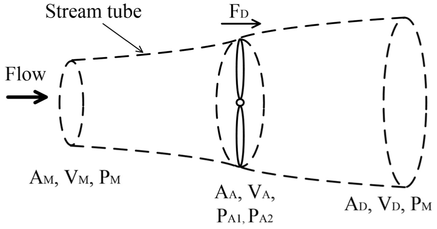
Figure 1 shows a schematic diagram of theoretical analysis model for bidirectional ducted turbine, considering a bidirectional tidal turbine placed in a uniform flow, in which the turbine is idealized as an actuator disk. An annular turbine area with a hub AA is taken as the turbine area and the ratio to the maximum duct area AD is taken as ARA. The equation for continuity in the duct gives the following.

Since the values of pressure at upstream and downstream of the duct are both the mainstream pressure PM, the following equation can be obtained.


Analytical model for bidirectional ducted tidal turbine.
In order to investigate the flow both inside and outside of the duct in detail, Bernoulli’s equation is divided into five sections and the energy loss through each streamline is considered in this paper. Ideally, a Bernoulli’s equation does not have an energy loss in an inviscid flow. On the other hand, the energy loss owing to the viscosity is avoidable in the viscous flow. Therefore, the value of efficiency is introduced in the Bernoulli’s equations in this paper.
If the flow efficiency of the upstream streamline ① is ηU, then the Bernoulli’s equation gives the following.

Next, if the flow efficiency of streamline ② in the upstream duct is ηD1, then the Bernoulli’s equation gives the following.

For the turbine section streamline ③, the turbine resistance coefficient K is defined as follows.

As with the upstream side, if the flow efficiency of the streamline ④ in the downstream duct is ηD2, the Bernoulli’s equation gives the following.

Finally, along streamline ⑤, the pressure is recovered to the mainstream pressure by the back pressure coefficient CPb.

In a uniform flow, the sum of the pressure difference from upstream to downstream (equations (3)– (7)) is zero as shown in equation (2). If the axial velocity ratio AVR is defined as follows, the value of AVR can be calculated from the sum of pressure.


Here, since the flow velocity at streamline ② is increasing flow, the value of ηD1 can be assumed as 1.0. Also, based on the experimental results of the wake of a sphere, 38 the value of CPb is set as −0.3 because the pressure in the wake of a blunt object decreases under the ambient pressure.
The maximum duct area AD is adopted as the reference area for the power coefficient CP to define CPD instead of CPT that is usually used, where CPT is based on the turbine disk area AT.


The turbine power output W can be calculated by using the turbine efficiency ηT as follows.

From the above, the power coefficient CPD based on the maximum duct area can be calculated as follows.

Ideal turbine power output for an open turbine
As a comparison with a ducted turbine, it is considered that the actuator disk theory model for unducted, open tidal turbine which is known as Betz limit, 13 which limit is referred as open Betz limit in this paper. Figure 2 shows a schematic diagram of the flow, focusing on a stream tube passing through an open turbine, and considering the case where the pressure recovers to the mainstream pressure PM at a location corresponding to the duct exit. Basic equations can be derived, that is, the continuity equation (15), the momentum equation (16) and the Bernoulli’s equations for upstream and downstream of turbine (17). Incorporating two equations (16) and (17), the equation (18) can be obtained. Finally, incorporating equations (15) and (18), the equation (19) can be obtained.



Therefore, the ideal turbine power output Wth is as follows.

The ideal power coefficient CPthD is the following, in which the maximum area of the stream tube is assumed to the maximum duct area.

In general, the ideal power coefficient CPthA defined by the turbine annular area AA (the same applies to the turbine disk area AT) is often used. 13

C PthA has a maximum value of 0.593 at the AVR value of 0.667, which is well-known open Betz limit. 13 On the other hand, CPthD has a maximum value of 0.385 at the AVR value of 0.789, where the limit value decreases as the reference area increases compared to the open Betz limit. The value of 0.385 for CPD is referred as the ducted Betz limit in this paper. The value of AVR can be calculated by K for open case as follows.


Actuator disk theory model for open tidal turbine.
Analytical results and discussions
Figure 3 shows the analytical values of the axial velocity ratio AVR for a bidirectional duct flow and the experimental value described afterward, plotted against the turbine resistance coefficient K. They are considered that the cases where the upstream flow efficiency ηU and the downstream duct flow efficiency ηD2 are 1.0 and 0.8, and for the ARA value of 0.231, which is the value of the experimental model described afterward, and for a larger ARA value of 0.5. The horizontal axis K represents the turbine loading, and it is observed that the flow collecting effect of the duct is large when the turbine loading is small. The case for the K value of 2 in the dotted line in the figure represents the case of open Betz limit, and the AVR value is only about the same as or less than 1.0 when the turbine power output is at its maximum. Also, when the area ratio ARA is small and the flow efficiency η is large, the AVR is large and the flow collecting effect is high. The experimental value at maximum CPD (the mark of solid circle), described afterward, is about the same as the analytical value.

Analytical and experimental values of AVR.
Figure 4 shows analytical and experimental values of power coefficient CP, with turbine resistance coefficient K on the horizontal axis. The values of CP are also normalized for an ideal case where the turbine efficiency ηT is 1.0. Furthermore, the four curves on the upside are the power coefficient CPD based on the maximum duct area, and the four curves on the downside are the power coefficient CPA defined by the turbine annular area AA. The reason why the CPA value is large is mainly because the reference area is small, therefore, the CPD value is mainly discussed as follows. Considering at the thick solid line (two values of η are 1.0 and ARA is 0.231) and the thin solid line (two values of η are 1.0 and ARA is 0.5), the maximum values for both exceed the ducted Betz limit of 0.385, and the thin solid line in particular shows a high value of about 0.4 even when the turbine loading K is large. The experimental values are about the same as those of the thick solid line.
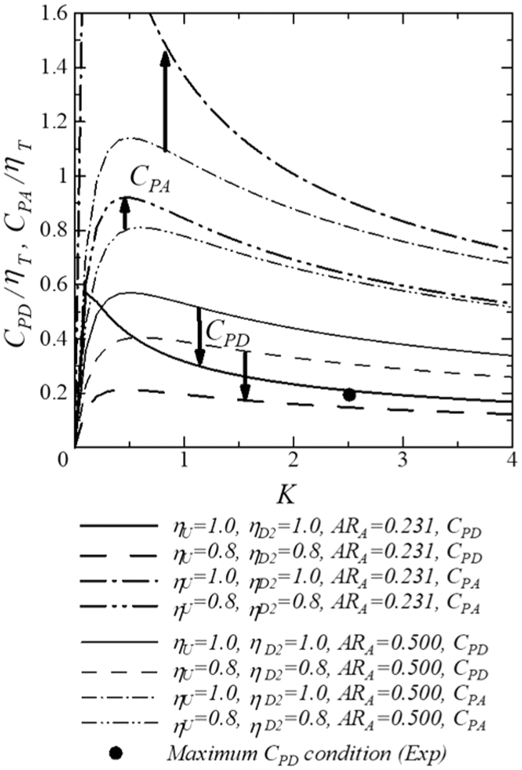
Analytical and experimental values of CPD and CPA.
Figure 5 shows the analytical and experimental values of power coefficient CP against the axial velocity ratio AVR. In addition to the analytical and experimental values, the ideal values of CPth (CPthD for ducted Betz limit is the thick dotted line, CPthA for open Betz limit is the thin dotted line) are also shown for comparison. Compared with the ducted Betz limit, the experimental value of CPD is larger than the value of 0.385, while the value of AVR which takes the peak value of CPD is close to 0.789. This figure shows that the experimental value of CPD can be improved by increasing the value of ARA if it is compared with the thin solid line (two values of η are 1.0 and ARA is 0.5).

Actuator disk theory model and present analysis.
In Figure 5, the thick solid arrows show the comparison between the case of ARA of 0.231 (larger maximum duct area) and 0.5 (smaller maximum duct area). Since the value of CPA does not vary with the maximum duct area, it can be observed that the turbine power output W increases with increasing the maximum duct area. On the other hand, the value of CPD, which takes the effect of maximum area interrupting the flow into consideration, decreases with increasing the maximum duct area if assumed that the flow efficiencies do not change.
Figure 6 again shows the ideal values of CPth for open case CPthA and ducted case CPthD. The value of 0.385 of CPthD based on the maximum duct area is obtained when AVR of 0.789 for the ducted Betz limit, while the value of 0.593 of CPthA based on the turbine area is obtained when the value of AVR is 0.667 for the open Betz limit. It is considered that the power coefficient CPD is preferable to CPA for the ducted turbine because the CPD can take into account the effect of maximum duct area. In all the best of author’s review so far, there is no criteria for the value of CPD. Therefore, the value of 0.385, the maximum value of CPthD, is a possible choice for the criteria to evaluate CPD.

Open Betz limit and ducted Betz limit.
Design of duct and turbine system
Table 2 shows the specifications for the bidirectional duct and the bidirectional turbine system for both the model and the prototype. The design parameters are set to a tidal current of 3 m/s, a turbine diameter of 10 m, and a turbine output of 0.62 MW. In the design of the bidirectional duct, the maximum radius of the duct RD is set to 1.8 times the turbine radius RT. The outline of the meridional geometry is shown in Figure 7, and a photograph of the experimental model is shown in Figure 8.
Specifications of tidal current turbine system.


Meridional view of bidirectional duct.

Experimental model of bidirectional duct.
The design method of Tsuru et al. 36 is adopted for a bidirectional ducted turbine for internal flow in turbomachinery methods. By using the turbine power as the design condition, the difference in the circumferential velocity between the upstream and downstream of the turbine is calculated using Euler’s equation. As the first step of the design method accomplishment, an axial velocity ratio AVR between the main flow and turbine inflow is assumed, and one-dimensional design is adopted. In order to work in the situation of bidirectional flow, the flat plate blades are adopted for a blade shape and the rotation of the turbine rotor changes according to the orientation of tidal current. The stagger angle of the reaction turbine blades is determined by using a two-dimensional potential flow. 36
In Euler’s equation, the difference in circumferential velocity between the upstream and downstream of the turbine ΔVθ is calculated using the following Euler’s equation, where < > denotes a characteristic value of the cross section as a one-dimensional design, and the rotational speed of turbine rotor at the blade tip is adopted for <U>.

Although the flow around the turbine is three-dimensional and varies in the radial direction actually, the characteristic values with the marks < > are used for the one-dimensional design. Figure 9 shows an overview of the turbine rotor designed for bidirectional flows.
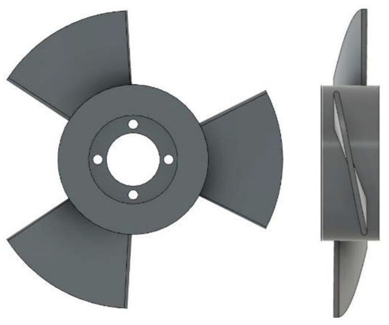
Designed bidirectional turbine rotor.
The advantage of this design method is as follows. Since Euler’s equation in the turbomachinery design is the equation which strictly keeps the angular momentum equation in mechanics, the torque of the turbine T accords with the difference in circumferential velocity between the upstream and downstream of the turbine ΔVθ if the value of is evaluated accurately. Therefore, the turbine power output W can be enhanced by arranging the flow around the turbine reliably.
Model experiment
The experimental equipment and procedure are the same as those of Tsuru et al. 36 The model and experimental equipment used in the circulating water channel experiment in Institute of Ocean Energy, Saga University is shown in Figures 10 and 11. The tidal current turbine test device is installed in the observation section of the circulating water channel, which is approximately 2.5 m long, 1.0 m wide, and 0.7 m deep. The blockage ratio BR, which is the ratio of the maximum duct area AD to the channel area, is 0.105 in this experiment.

Experimental model bidirectional duct and turbine.

Experimental apparatus.
The main flow velocity VM is set at 1.0 m/s and the turbine rotational speed ω is stepwise changed from 150 to 350 min−1 to measure the velocity at turbine VA, the turbine torque T, the pressure drop through turbine ΔP and the thrust force FT. The uncertainties are calculated by the method of Coleman and Steele 39 with a 95% confidence level. Table 3 shows the results of the uncertainty U, the system uncertainty B and the random uncertainty P for the experimental data, respectively.
Experimental uncertainties.

Experimental results and discussions
The experimental results are shown with the tip speed ratio TSR (=U /VM) on the horizontal axis. Figure 12 shows the axial velocity ratio AVR, Figures 13 and 14 show the power coefficients CP, Figure 15 shows the torque coefficient CQ and Figure 16 shows the thrust coefficient CT, respectively. The power coefficient CPD based on the maximum duct area can be divided into the duct efficiency ηDUCT and the turbine efficiency ηT as follows.

Also, the torque coefficient CQ and the thrust coefficient CT are defined as follows.


Experimental values of AVR.

Experimental values of efficiencies.

Experimental values of power coefficient.

Experimental values of torque coefficient.

Experimental values of thrust coefficient.
It is known that the blockage of the turbine area to the channel area influences the turbine performance, and Garrett and Cummins 40 have proposed a factor of (1-BR)−2, where BR is the blockage ratio of the maximum duct area, which means that the turbine performance such as power coefficient increases if a mainstream is confined.
Figure 12 shows the value of AVR, where a vertical line is added at the TSR value of 2.56 for maximum CPD value. The experimental results of Tsuru et al. 36 showed that the effect of blockage ratio on the value of AVR is quite small as far as this type of bidirectional duct, therefore, the correction for AVR by the effect of BR is not done in the figure. It is observed that the value of AVR is almost in proportion to the value of TSR.
Figures 13 and 14 show the values of CPT, CPD, ηDUCT and ηT respectively. These values excepting ηT are considered to be increased by the blockage ratio of 0.105 in the experimental equipment, which are shown by the symbol *. The value of CPD* takes maximum value when the value of ηT is at its maximum, therefore, the influence of ηT is greater than that of AVR.
Table 4 shows the experimental maximum values of efficiency shown in Figure 13, in which the values of criteria for the turbine and the power coefficient are listed. As for the turbine, the ideal value of efficiency is 1.0 because the flow is internal flow in the duct. The experimental maximum value of ηT is 0.483, that is, about a half of the criteria. The design method in the paper is still much room for the improvement such as the followings. The axial velocity ratio AVR between the main flow and turbine inflow is assumed. And in order to work in the situation of bidirectional flow, the flat plate blades are adopted for a blade shape and the rotation of the turbine rotor changes according to the orientation of tidal current. The present design method is limited to more or less within the simple manner so far, therefore, future works are desired such as the prediction of AVR and the asymmetrical blade geometry suitable for bidirectional flow.
Experimental maximum values of efficiency.

As for the duct efficiency, the experimental maximum value of 0.193 for ηD is more or less small compared to the value of 0.385 of the ducted Betz limit. As Liu et al. 37 pointed out, since the effect of separation vortex in the flow around the duct is significant, the performance of the turbine system may be further improved by suppressing the flow separation around the bidirectional duct especially for the flow around the upstream duct.
Lastly, the experimental maximum value of CPD is 0.093. although the value of 0.093 is quite small for the moment compared to the value of 0.385 of the ducted Betz limit, this comparison shows that the ducted Betz limit functions properly as a reference of CP for the ducted tidal turbine.
Figure 15 shows the value of CQT and CQD, where they are shown by the symbol * because of the blockage effect. In the case of torque coefficient, CQT based on the turbine disk area is considered to be more significant than CQD based on the maximum duct area because the self-starting characteristics should be decided by the turbine itself. The value of CQT* at the TSR value of 2.56 is approximately 0.15, which is so quite larger than usual propeller type horizontal axis turbine that the self-starting characteristics of the turbine is preferable to usual open propeller turbine owing to the sinusoidal variation of tide velocity in time. The reason of the consideration in this paragraph is that the usual peak CQ value of a horizontal-axis open-propeller is more or less around 0.05 in the reference of Fraenkel. 41
Figure 16 shows the value of CT, where it is shown by the symbol *. The curve of CT* is comparably flat with TSR and the value of CT* is 2.05 at the TSR value of 2.56, which is more or less large compared to open turbine. It is considered that the flow separation should occur around the bidirectional duct largely, 37 which may be reduced by optimizing the duct geometry in the further work, for example, the value of ARA is increased to 0.5 as mentioned in Figure 5.
Conclusions
This work investigated a combination system of a bidirectional duct and a bidirectional turbine using a theoretical analysis and an experimental study. The major conclusions can be summarized as follows:
(1) A theoretical analysis was proposed for the ducted tidal turbine, in which the power coefficient based on the maximum duct area CPD was mainly adopted instead of the power coefficient based on the turbine area. It was observed that the turbine power output increased with increasing the maximum duct area, whereas, the value of CPD, which took the effect of maximum area interrupting the flow into consideration, decreased with increasing the maximum duct area if assumed that the flow efficiencies did not change.
(2) The maximum value of 0.385 of power coefficient by the actuator disk theory CPthD based on the maximum duct area was found and proposed as the ducted Betz limit for ducted turbine. It was considered that the power coefficient CPD was preferable for the ducted turbine because the CPD could take into account the effect of maximum duct area. The value of 0.385 was a possible choice for the criteria to evaluate CPD.
(3) The design method of turbomachinery was adopted for a bidirectional ducted turbine for internal flow. Using the turbine power as the design condition, the difference in the circumferential velocity between the upstream and downstream of the turbine was calculated using Euler’s equation. The advantages were that the torque of the turbine accorded with the difference in circumferential velocity between the upstream and downstream of the turbine if the value was evaluated accurately because Euler’s equation in the turbomachinery design was the equation which strictly kept the angular momentum equation in mechanics. Therefore, the turbine power output could be enhanced by arranging the flow around the turbine reliably.
(4) The experimental maximum value for the duct efficiency was 0.193 was more or less small compared to the value of 0.385 of the ducted Betz limit. Since the effect of separation vortex in the flow around the duct was significant, the performance of the turbine system might be further improved by suppressing the flow separation around the bidirectional duct especially for the flow around the upstream duct.
(5) The experimental value of torque coefficient was quite larger than open horizontal axis propeller turbine, which was preferable for the self-starting characteristics because tide velocity varied sinusoidally in time.
Limitation and future work
The theoretical analysis proposed in this paper has a limitation of accuracy because the back pressure coefficient is assumed as the value of −0.3. For the future work it is desired to investigate the back pressure in the wake of the duct.
The present design methodology of bidirectional turbine rotor is limited to more or less within the simple manner such as the assumption of AVR and the adoption of flat plate blade shape, therefore, future works are desired such as the prediction of AVR, the adoption of asymmetrical blade shape suitable for bidirectional flow.
The maximum value of 0.093 for CPD is quite small for the moment, therefore, ηT and ηD should be improved. Future improvements are desired such as turbine blade shape for ηT and the duct geometry for ηD.
Footnotes
Appendix

Funding
The authors disclosed receipt of the following financial support for the research, authorship, and/or publication of this article: This work was financially supported by The Iwatani Naoji Foundation and JSPS KAKENHI Grant Number 25K08547.
Declaration of conflicting interests
The authors declared no potential conflicts of interest with respect to the research, authorship, and/or publication of this article.