
Abstract
Cf/SiC composite is a typical heterogeneous brittle composite material, its precision machining has always been affected by the complicated removal mechanism. This paper conducted a single diamond grit scratching experiment on the unidirectional Cf/SiC composite to investigate the material’s mechanical response under different loads and scratching depths. The scratching force and acoustic emission signals were measured to reveal the removal characteristics. The scratching removal behavior of SiC matrix and carbon fibers in the two-phase component of unidirectional Cf/SiC composites was analyzed based on the fracture size and fiber fracture morphology. The results show that the parallel scratching process could produce a better strength resistance with mild rupture features of fiber extrusion fracture and shear removal. While the perpendicular scratching process is generally resulting in crack propagation along the fiber direction with interface failure and bending fracture failure along the moving direction.
Keywords
Introduction
Ceramic matrix composites (CMCs) are widely used in high temperature, wear and chemical resistance applications because of its high impact and fatigue resistance performance.1–3 Typical Carbon Fiber-reinforced Silicon Carbide matrix Composite (Cf/SiC) is generally composed of carbon fiber reinforcement, pyrolytic carbon interface, and silicon carbide ceramic matrix material. 4 Compared with traditional structural ceramics or carbon fiber reinforced resin matrix composites, Cf/SiC composites have demonstrated improved mechanical properties in engineering applications,5–8 such as high strength, high modulus, light mass, anisotropy, high flexural resistance, etc. However, the heterogeneous structure of the carbon fiber and SiC makes the precision machining more difficult9–12 in dealing the typical interface debonding, fracture cracks, delamination, burrs and etc. Therefore, a good understanding of the effective machined method and its related removal mechanism is helpful in promoting the engineering applications.
Compared with metallic materials, Cf/SiC composites are always affected by high processing difficulties and costs, thus limiting their wide application in industrial fields.13,14 Currently, the commonly used machining methods include conventional mechanical machining15,16 (milling, turning, and drilling), laser machining, 17 electric discharge machining,18,19 and abrasive water jet machining.20,21 In practical applications, grinding of Cf/SiC has been reckoned as one of the most effective methods for machining of this material.22,23 However, the grinding process is generally featured by numerous abrasive grits superposition at negative rake angle,24,25 together with the fiber direction, 26 the grinding mechanism could be more complicated.
During the grinding process, amount of abrasive grits involved in the cutting motion simultaneously could help to remove extremely thin and fine chips,27–29 which can effectively reduce machining defects and obtain better surface quality. However, the grinding mechanism for Cf/SiC has not been fully investigated, resulting in unavoidable surface defects in grinding processed Cf/SiC composites, which affects the quality and use of the components. 30 Azarhoushang 31 even conducted segmented diamond wheels experiments in high speed deep grinding of carbon fiber-reinforced ceramics. Therefore, although the grinding process of Cf/SiC composites has been fully applied in precision machining, it is particularly important to understand the material removal mechanism through a single grit scratching process.
Scratching tests are mostly used to investigate the material damage removal mechanism,32–36 and unidirectional Cf/SiC composites can effectively avoid the interaction of fibers in different directions, which is an ideal method to understand the removal mechanism. Li et al. 37 conducted single grit grinding mechanism of Cf/SiC through finite element simulation by analyzing the grinding forces and related fracture features. Chen et al. 38 and Li et al. 39 conducted nano-scratching experiments by reveal the transformation of fracture mechanism, which gives direct experimental analysis of the fracture topography and related mechanical responses. Liu et al 40 conducted an in-depth experimental analysis of the surface quality of silicon carbide grinding by a single abrasive test method. Sanchez et al. 41 conducted a series of single abrasive scratch tests while collecting the acoustic emission signals generated by the scratching process, and combined with the surface characteristic morphology of the scratches, concluded that there is a clear link between the acoustic emission signals and the material removal process. In the meanwhile, the single grit method also is applied in scratching of SiCf/SiC,42,43 which is a new attempt to more advanced CMCs’ component manufacturing. Nevertheless, the above scholars did not consider the impact load generated by the diamond abrasive grains and the material when the scratching speed was too low in the process of scratching the Cf/SiC composite material with a single abrasive grain. Single diamond grit scratch test was used as a method to study the mechanism of material removal in grinding wheel grinding. In general, there are countless grains on the surface of the grinding wheel in the grinding process. Each abrasive is ground along the scratches left by the previous abrasive grain or multiple abrasive grains. The contact between the abrasive grains and the material is extremely stable. However, in the single abrasive grain scratch test, only the relative static removal has not been considered in the past for the modeling or experiments of real situation. In fact, the relative static scratching process can give some evidence for the initial deformation of materials, which should be widely focused and has a great contribution to further illustrate the removal mechanism of materials in grinding.
In this study, a single-factor scribing process experiment was designed based on diamond indenter for unidirectional Cf/SiC material by varying the process conditions such as scratching force and fiber orientation. Meanwhile, the scratching force and acoustic emission signals were measured to reveal the removal characteristics. The scratched surface is observed through the microscopic and SEM figures, which could give detailed grooves information and surface fracture mechanism. This paper could give some direct material’s mechanical responses in relatively static scratching removal process, which will give more theoretical basis for efficient grinding of Cf/SiC.
Materials and scratching methods
Single grit scratching setup
The diamond indenter scratching test was performed at WS-2005 Automatic Scratch Tester in Figure 1. It shows the test setup for the scratching test that is divided into three parts: the constant load system, the feeding system, and the data acquisition system. The single crystal diamond indenter used in the test has a taper angle of 120°, tip half warp radius R of 0.2 mm. The Cf/SiC workpiece is fixed on the table fixture, which has a perpendicular or parallel clamping direction with fiber axial direction. The constant load system and the feeding system are controlled by the connected computer with software. The Acoustic Emission (AE) signal collector (piezoelectric buzzer SL-B20E6.0A) is attached above the main body of the instrument to measure the acoustic emission signal generated during the scratching test and its frequency of sample is 60 Hz. The force sensor (FSA-2) has a comprehensive error and a repeatability error of 0.05% F.S and 0.03% F.S with a maximum range of 200 N, which is attached to the bottom of the loading beam to test the real-time dynamic load. Moreover, the measuring accuracy of the force is 0.01 N, and its frequency of sample is 60 Hz. The Acoustic Emission (AE) signal and force signal can be detected in real time and output to the computer for data conversion and processing.
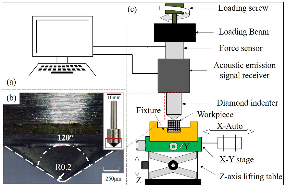
Diamond indenter test device setup: (a) data acquisition, (b) diamond indenter topography, and (c) scratching equipment structure.
Workpiece preparation
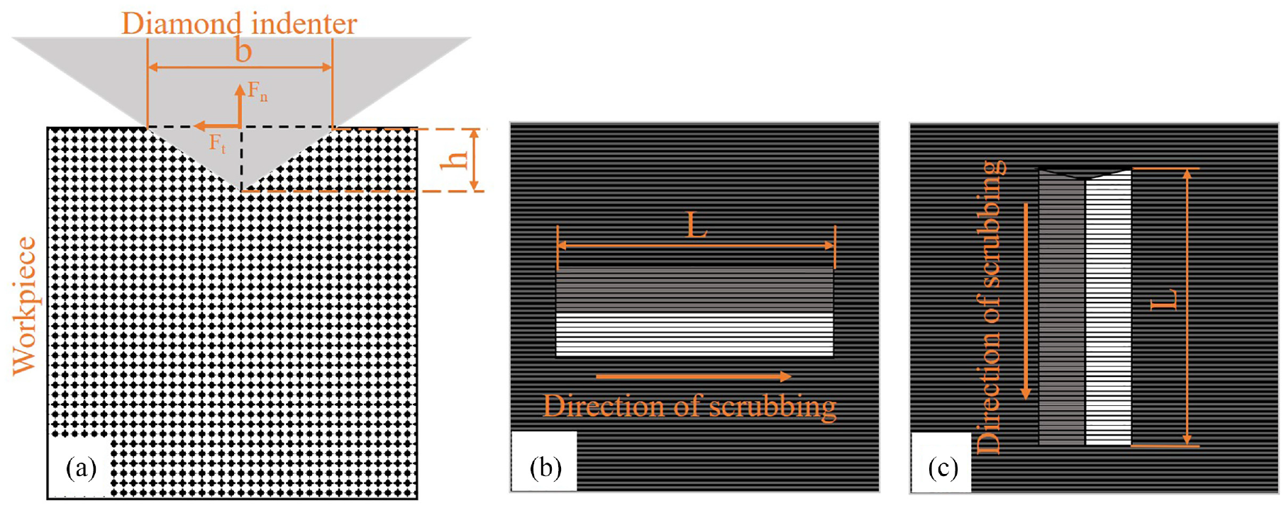
The material used in this study is a unidirectional Cf/SiC composite made by chemical vapor infiltration (CVI), which is a cube with a cubic size of 15 mm × 15 mm × 15 mm. The composite shows heterogeneous material characteristics due to their structural features. Its main compositions are SiC matrix, T300 carbon fiber reinforced phase and pyrolytic carbon interface, which has a 40% volume fraction of carbon fiber. The main function of the pyrolytic carbon interface is to protect the carbon fiber from damage during chemical vapor deposition, explaining the removal mechanism of the Cf/SiC composite in this experiment does not distinguish it from the SiC matrix. 39 The main mechanical properties38,39,44 of Cf/SiC composite and its main compositions at room temperature are shown in Table 1. It can be found that the axial mechanical strength is much higher than the transverse direction.
Material properties at room temperature.
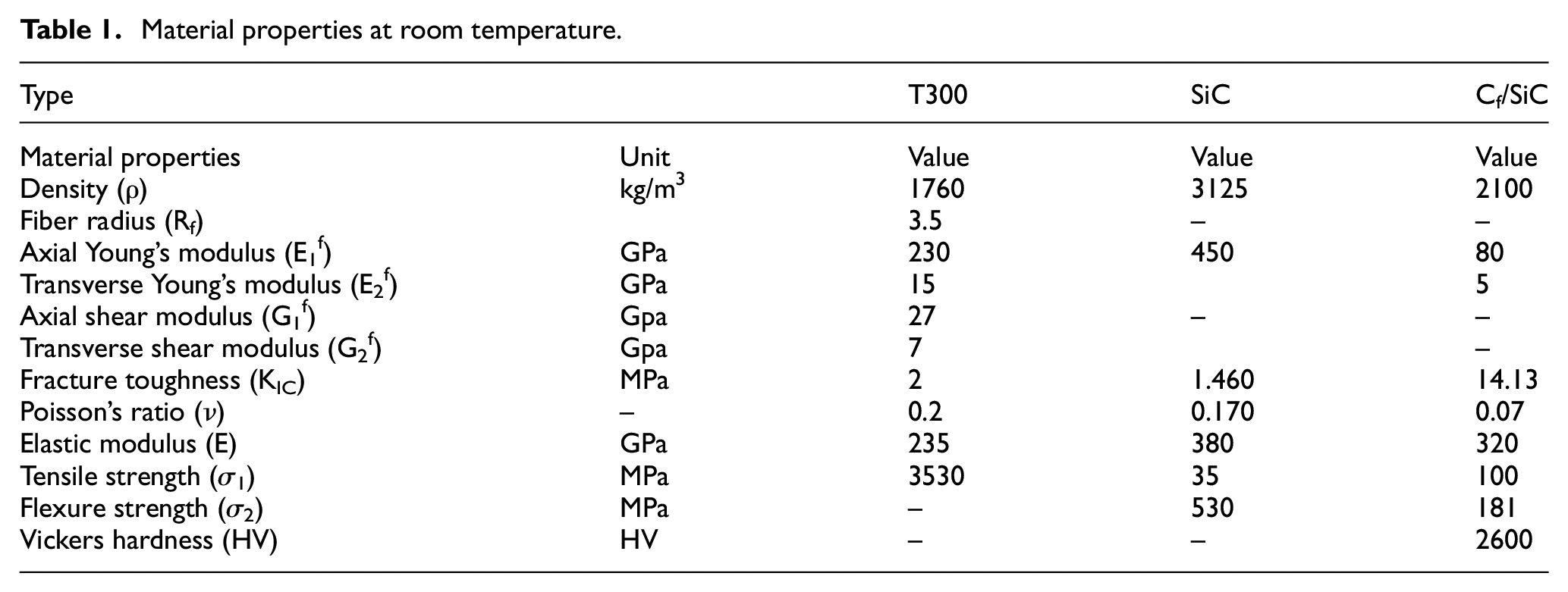
In this paper, the composite material fiber directions are all in one direction parallel to each other. Two scratching grooves, SA and SB, were defined based on the difference between fiber directions and scratching directions. As shown in Figure 2, the SA scratching groove is parallel to the scratching direction (0° direction), while the SB scratching groove is perpendicular to the fiber direction (90° direction). The scratching area is selected with relatively flat surface and free of defects such as fiber burrs, bumps and pits. Before conducting diamond scratching tests on unidirectional Cf/SiC composites, the material has been pretreated by the following procedure.
Scratching grooves of SA (parallel) and SB (perpendicular) to fiber direction.
(1) Polishing: Adopting a series of diamond paste with particle size of 40, 28, 20, 16, 10, 7, 5, 3, 1, 0.5 μm to polish, the workpiece is manually mechanically polished until the material had no obvious surface defects and showed mirror reflection. (2) Cleaning: Put polished samples into alcohol and clean it with a KM-900T ultrasonic cleaner from Kejiemeng Experimental Instrument Co., Ltd. Alcohol and purified water is used as cleaning agents to remove water-soluble grinding paste and residual organic solvents after material production. After cleaning the material with the ultrasonic machine for 5 min, replace the cleaning solution. Repeat the above steps until the cleaning waste liquid is clear and transparent. (3) Drying: Place the cleaned workpieces on the microcomputer heating platform JF-966 workbench respectively, set the heating temperature to 80°C, and keep it for 10 min.
Experiments setup
As shown in Figure 1, at the beginning of the scratching test, the polished, cleaned, and dried workpiece is clamped on the scratching test fixture. Since the scratching indenter moves from left to right, adjusting the XY axis knob to move the upper left of the workpiece to just below the scratching indenter. Then the loading screw can be pre-rotated so that the loading beam is able to contact the prominent parts of the loading screw, followed by adjusting the Z-axis knob until the dynamic load indication on the software reaches 0.1–0.3 N. After that, according to the test parameters, the load, loading rate, and scratching distance can be set, and then execute the command of “scratch with constant load.” After scratching, the scratching instrument will be unloaded first, so that the scratching indenter will leave the surface of the material, and then return to the original X position to complete a scratching test. The subsequent scratching test repeats the above test steps according to different scratching test parameters.
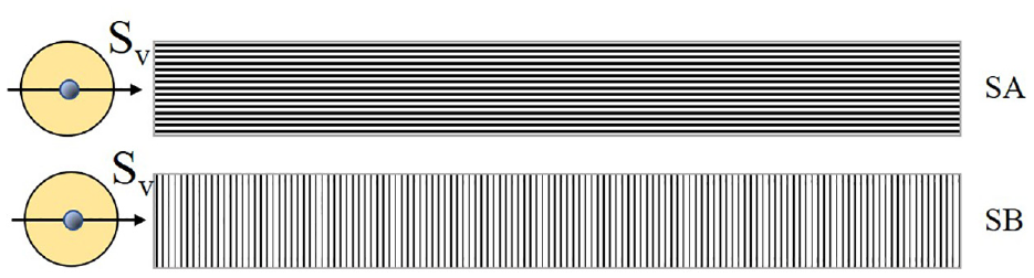
In order to investigate the indentation and scratching performance under the loaded force, the detailed scratching experiments are depicted in Figure 3. In this figure, the diamond scratching test cross section for side view and top view is given with specific parameters and scratching directions. The indenter micro geometry and cutting-edge radius of the diamond indenter are shown in Figure 1(b). In Figure 3, b is the width and h is the depth of the scratches measured after the scratching test. The parameters for diamond indenter have been given in Section “Single grit scratching setup.”
Diamond scratch test: (a) side view and (b and c) top view at different direction of scratching test.
The tip angle of diamond indenter in Figure 3 is 120°, and the cross-sectional area S of the pressed-in material can be calculated as:

where
In this paper, the determination of the parameters is decided by both of the materials strength and surface pre-scratching topography, which can guarantee a reasonable scratching load with fracture groove. In pre-scratching tests, the indentation force and the scratched cross-sectional area were measured when the indentation load was 1 N and the scratching direction was perpendicular to the fiber direction. Then find out that the ratio is greater than the fracture toughness of the material, so it is determined that the indentation load can meet the requirements of scratching the material.
However, when the indention load is less than 1 N, the diamond indenter cannot scratch the material with obvious groove in the scratching test. Therefore, the minimum value of indentation load in this paper is selected as 1 N. When the indentation load exceeded 5 N, the surface of the material was severely damaged, resulting in a form of removal of the substrate from the carbon fiber that could not be effectively observed. According to several pre-scratching tests, the detailed testing data is given in Table 2, which is the indentation load Fn of 1, 3, 5 N, loading rate of 5 N/min, and scratching length L of 6 mm. Considering the short scratching distance of 6 mm and low indentation load of 5 N (maximum of 200 N), the indenter tip wear is very small and can neglected, thus it is not measured and analyzed in this paper. The typical wear process can be summarized as the following process.
Parameters of scratching test.
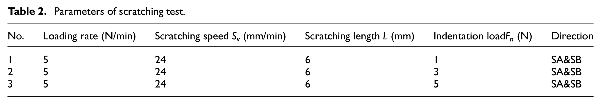
During the single grain diamond scratching test on unidirectional Cf/SiC composites, the diamond indenter tip wears to a fine degree and the shape of the cutting-edge changes continuously. As the scratching test progresses, the sharp tip of the diamond indenter flattens out, resulting in a reduction in overall diamond indenter height and an increase in cutting edge radius, with more wear occurring closer to the tip. In addition, flattened diamond indenter has a larger contact area with the material than the theoretical value. With the same scratching depth, the flattened diamond indenter generates more scratching force and therefore wears more severely. After the diamond indenter becomes dull, the indenter continues to be used for the scratching test, and the wear accumulates and the indenter becomes duller. The flattening process of the indenter becomes more and more rapid because of the greater scratching force generated by the indenter in contact with the material, but after a certain level of wear, the indenter wear tends to level off.
The scratch depth h and width b of the scratched workpiece is measured by using the HIROX-KH-7700 3D optical microscope in Figure 4 for three times’ test, which could provide a maximum of 3500× magnification and 3D view for topography quantitative test. The test device configures with a supporting software that allows testing the cross-sectional shape and size, and the average depth and average width of SA and SB scratches indicated by multiple measurements is obtained.
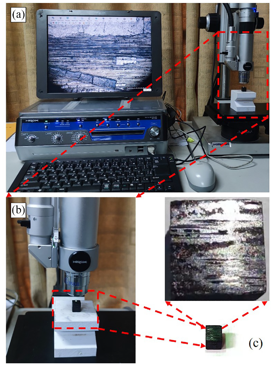
Measurement of scratches with the HIROX-KH-7700 3D optical microscope: (a), (b) are the measured figure and (c) is the workpiece.
Results and discussion
Scratching grooves analysis
The microscopic topography of the scratched surface was observed after the diamond indenter scratching by the HIROX-KH-7700 optical microscope in Figure 5. Figure 5(a) is the scratched surface for parallel direction, and Figure 5(b) is the perpendicular direction. The inner area of the dotted line is the scratched groove. It can be found from Figure 5 that carbon fiber shows significant anisotropy in perpendicular and parallel direction. The scratched grooves are relatively flat when it is parallel to the fiber direction in Figure 5(a), and there are no obvious defects such as fiber buildup, bumps, and burrs, caused by broken carbon fibers. While when the scratching direction is perpendicular to the fiber direction in Figure 5(b), the damage is extremely drastic on both sides of the scratches, and there are obvious defects of carbon fiber pulling out and broken fiber exposure.
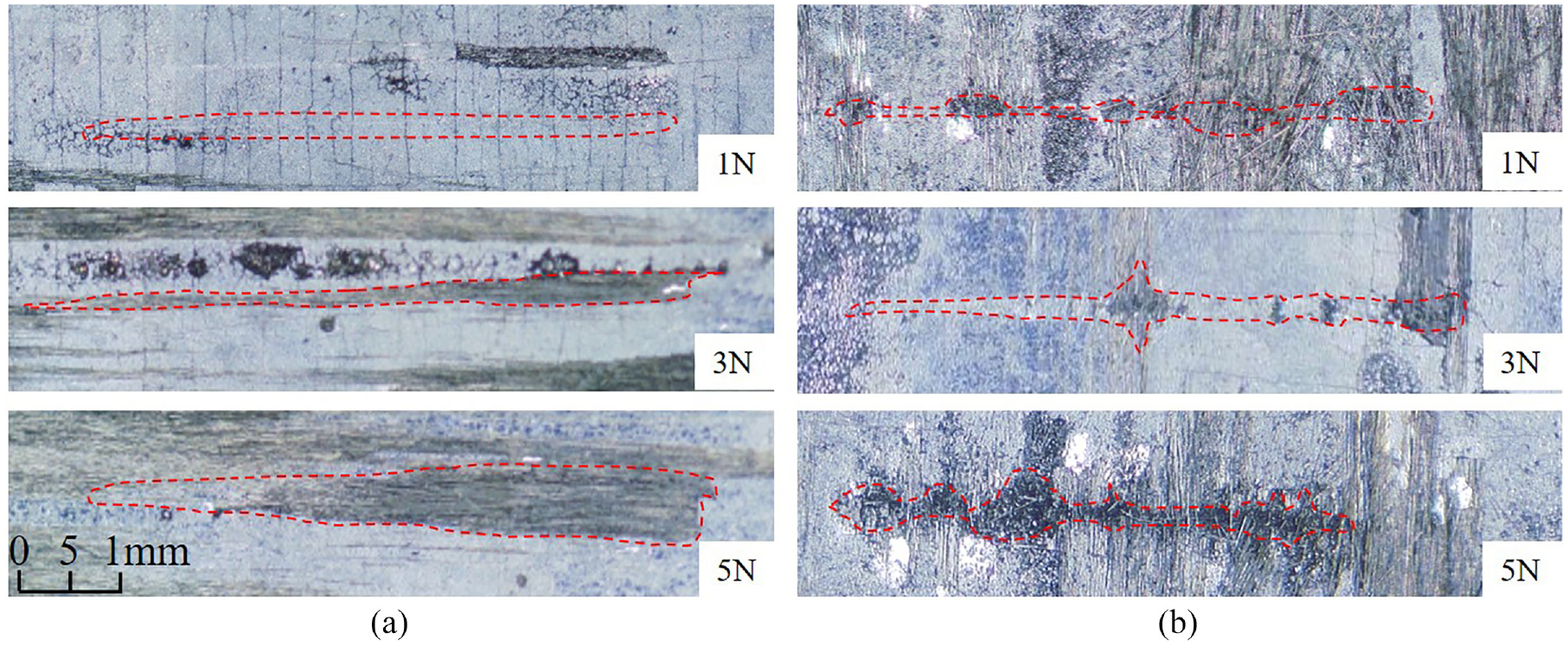
Scratches along different fiber directions: (a) is for the SA direction and (b) is for the SB direction.
The enlarged feature for scratching grooves is given in Figure 6, which gives the detailed information for the groove depth and width under different loads. In Figure 6(a), (c), and (e) are scratched surface grooves at SA, and (b), (d), and (f) is SB direction. The corresponding size data is given in Table 3, which is average of five points.
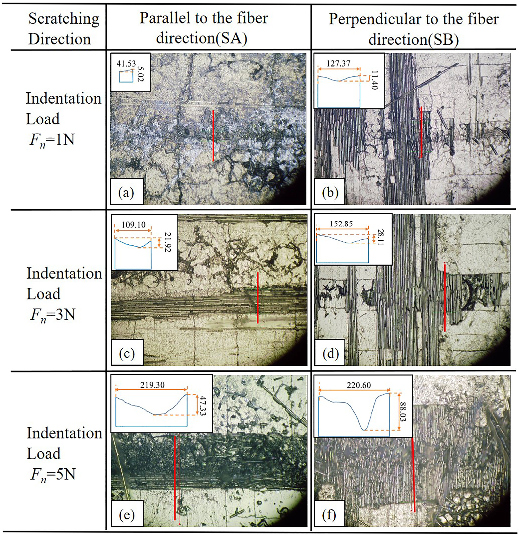
Scratch grooves with depth and width measurement: (a, c, and e) are SA at different loads and (b, d, and f) are SB at different loads.
Average depth and width of scratches.
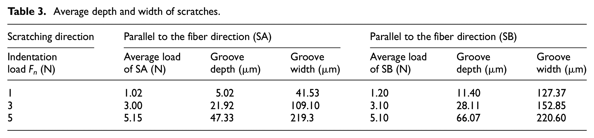
From the grooves in Figure 6, it can be found that the groove depth and widths increase with the elevation of indentation load, accompanying an increasingly severe surface damage and extended groove. With the increase of the load, the stripping damage of silicon carbide matrix occurs first when scratching, the fracture of the carbon fiber has no obvious effect on the matrix, then the scratch width gradually increases with the diamond scratching load gradually increases. Moreover, from the grooves in Figure 6 with the same load, the groove for perpendicular direction is broader in disorder which is caused by the reason that the carbon fiber is more fracture resistant in SA direction.
Since Table 3 gives exact data of the measured grooves, the effect of the scratching load on the materials’ removal could be calculated by the produced force on the unit cross section of the diamond indenter. From Figure 3, the indented load is Fn, and the corresponding scratched force is Ft. The scratched force Ft applied to the diamond indenter during the scratching test can be expressed as the compressive stress index Kσ, which can be given as 45 :
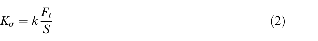
Where S is the cross-sectional area of the indented part of the diamond indenter, which is expressed in formula (1). In formula (1),

Where μ is the coefficient of friction and deformation between the diamond indenter and workpiece, which can be given between 0.5 and 0.8,46,47 0.6 is adopted in this paper. Thus, the cross-sectional area and the compressive stress index Kσ is given in Table 4.
The cross-sectional area of the indented part of the diamond indenter.
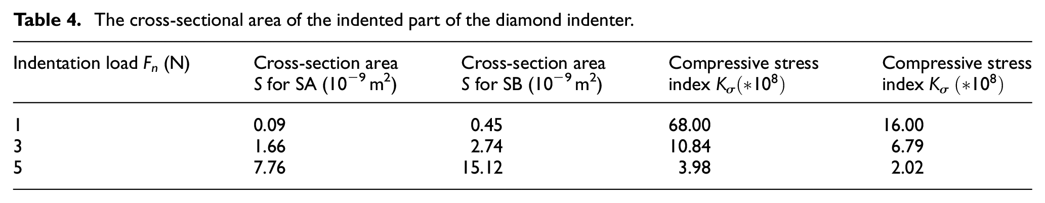
Figure 7 depicts the compressive stress index and the direction ratio variation, which shows that the Kσ decreases with the increase of indentation load from 1 to 5 N. Moreover, the compressive stress index Kσ for SA is much higher than SB direction, which is 4.25 at 1 N, 1.6 at 3 N, and 1.97 at 5 N. The direction ratio λ at 1 N is more than two times at 3 and 5 N, which could be expressed with the scratched surface in Figure 6. In Figure 6, the friction is main source for the surface topography, few material removals occur in SA direction, thus the actual Ft should be lower than the calculated value in formula (3). From another perspective of Table 1, the material Properties at room temperature for SA direction is much higher than SB direction, with a strength ratio of 15.3 for Young’s modulus and 3.85 for shear modulus. It could be found that the reason for these characteristics is the carbon fiber shows higher mechanical strength in SA direction.
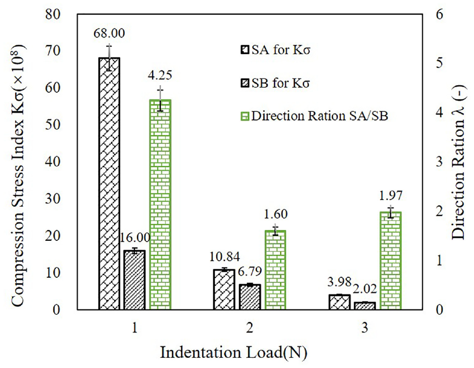
Compressive stress index and the direction ratio variation.
Material removal mechanism
The scratched surface under microscope observations of unidirectional Cf/SiC composites were carried out on Scanning Electron Microscopy, and the results are shown in Figure 8 for SA direction and Figure 9 for SB direction. The magnification is 500 times and enlarged 2000 times. It can be found that the scratched surfaces show different fracture features with different fiber orientations. From the topography of Figure 8(a), the scratched surface is mainly produced by micro friction with no material removal process, which can be proved by the AE signal in Figure 11. While with the increase of indentation load to 3 N, the material is broken with Silicon Carbide matrix fracture, interface debonding. The fibers in Figure 9(b) mainly keeps intact without rupture, few cracked fibers show a shear fracture by the indentation load in normal direction. However, when the load increases to 5 N, the fiber shows severe damage of fracture debris, together with mix interface fracture of debonding and phase fracture.
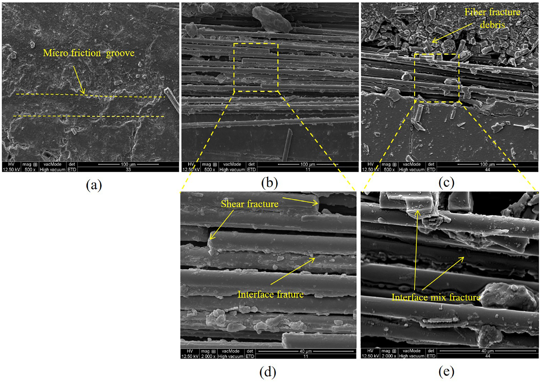
SEM images of scratches parallel to the fiber direction: (a) load of 1 N, (b and d) 3 N, and (c and e) 5 N.
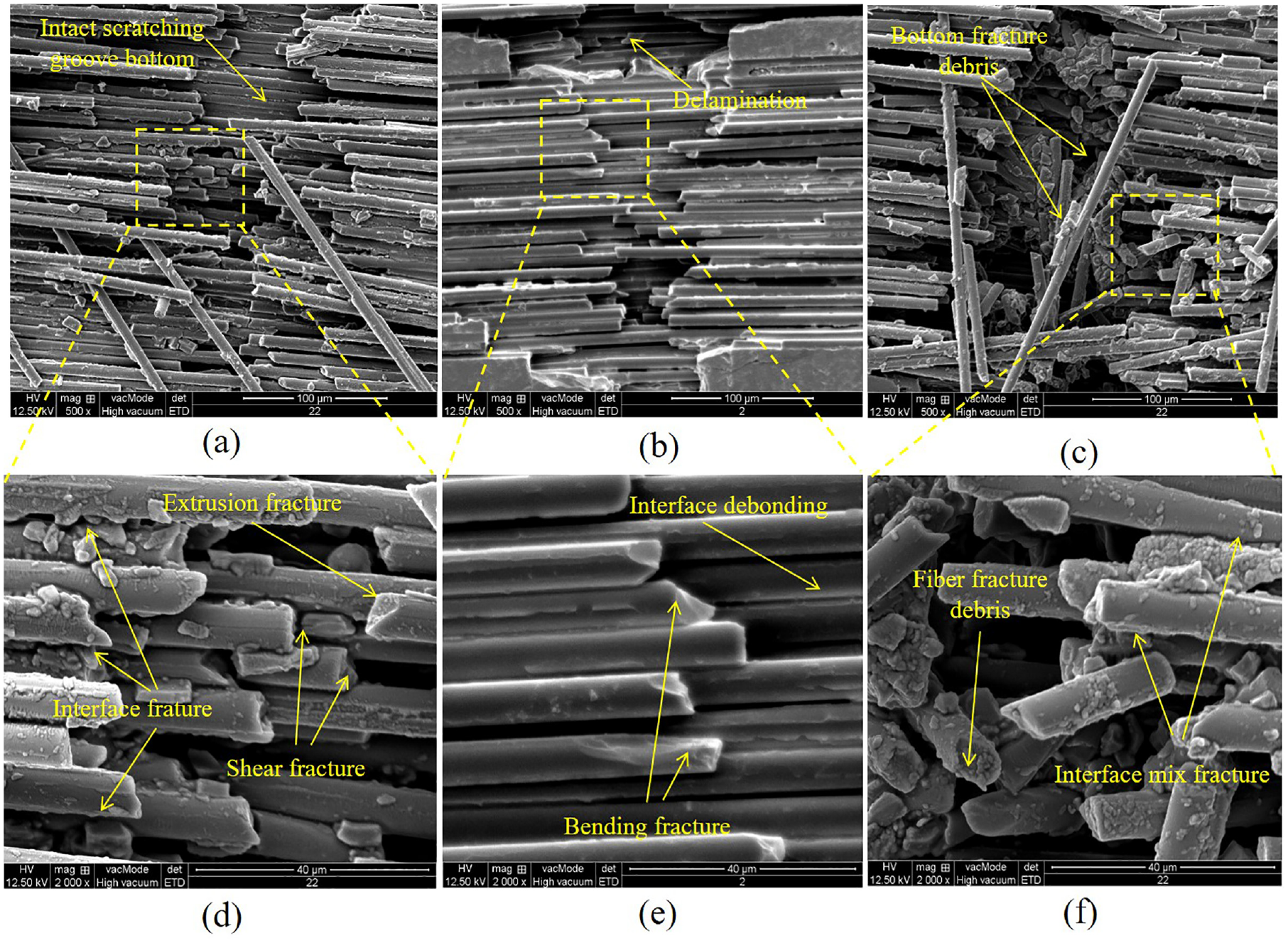
SEM images of scratches perpendicular to the fiber direction: (a and d) load of 1 N, (b and e) 3 N, and (c and f) 5 N.
When the scratched direction is perpendicular to the fiber direction in Figure 9, the SEM topography shows a different removal mechanism. When the load is 1 N, the scratching groove keeps an intact groove bottom without fiber rupture. Moreover, the broken part shows a complicated fracture mechanism, with shear fracture in the bottom position by normal force, extrusion fracture at the fiber fracture appearance and interface fracture with cracks attached. When the indentation load increased to 3 N, the Cf/SiC shows a delamination by massive interface debonding and fiber fracture of bending features in Figure 9(e). From the Figure 9(c) and (f) of 5 N, the scratched groove shows a severe bottom fracture damage, which is much deeper than the actual indenter depth. This means that the load exceeds the critical load, which causes fracture cracks propagated along the normal direction. In the meanwhile, the enlarged image of Figure 9(f) reflects that both the fiber and interface is under severe rupture with multiple fracture modes.
Based on the above analysis of the experiments, the typical failure features in scratching process is summarized in Figure 10, with the typical failure modes of fiber materials 48 in Figure 10(e). As illustrated in Figure 10, when it is scratched in SA direction, the crack is first propagated at the tip of indenter along the normal and scratched direction. While when the load reaches the critical load, the fiber is removal by grit extrusion along moving direction, shear removal along normal direction. In the meanwhile, this process is also accompanied with the interface failure and random cracks propagation. In the SB scratched direction, the cracks are produced at a more severe intensity for the lower transverse strength. The cracks are generally propagated along the fiber direction with interface failure, also perpendicular bending fracture failure. Affected by the lower transverse strength, the normal direction could cause severe bottom damage by crack propagation and the fiber is cracked in pieces with a multiple fracture mechanism.
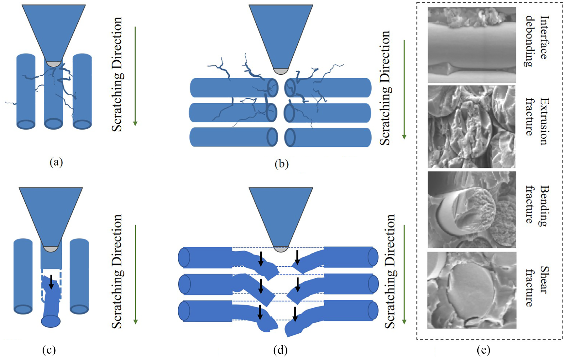
Typical failure features in scratching process: (a) crack propagation for SA, (b) crack propagation for SB, (c) fiber failure for SA, (d) fiber failure for SB, and (e) failure types.
The transition from Figure 8(a) elastic scratch to (b) brittle fracture can reflect the plastic-brittle transition of the material. According to the indentation fracture mechanics, when the diamond indenter is in contact with the material, it is in the rub stage, and the deformation in this stage is elastic deformation. If the load is withdrawn at this point, the material will return to its original shape due to elastic deformation. As the diamond indenter presses into the load increases, the indenter will make the material along the scratch to produce material stacking, this stage is called the plowing stage. This stage of deformation for the elastic-plastic deformation, if the indenter in this stage to withdraw the load, the material due to elastic deformation will occur some recovery, but will not be completely back to the original shape, the plowing stage of the formation of scratches will also be retained. The indentation load of the indenter continues to increase until the indentation load exceeds the critical load and the material undergoes brittle fracture, generating a large amount of debris. The unidirectional Cf/SiC composites exhibit a clear transformation of the brittle-plastic removal mechanism, where the material undergoes a process of “plastic removal – brittle-plastic transformation – large size brittle fracture.”49,50
Scratching forces and AE signals analysis
The scratching force and Acoustic Emission (AE) signal could help to illuminate the internal mechanism of material removal process. In the general practice, the force is reckoned as an important indicator for investigating the material removal mechanism. Besides the scratching force, this paper gives the AE signal to analyze the mechanical responses during the removal process. Based on the scratching test with diamond indenter on the unidirectional Cf/SiC composite material, the acoustic emission signals and force signals generated by the scratching process are collected.
Figure 11 is the scratched dynamic indentation force and AE intensity under the pre-indented load of 1 N. As shown in Figure 11, the acoustic emission signal in the SA direction is small, the maximum is 5, and the force signal is stable, with fluctuations within 0.1 N. This indicates that no material removal occurred during the scratching test and the surface remained intact, which is consistent with the analysis of Figure 8(a) in Section “Material removal mechanism.” Combined with Figure 5(b), it can be seen that the material is damaged in the SB direction, but it can be seen from Figure 9(a) and (d) that the material damage is not serious. And it can be seen from the analysis in Section “Material removal mechanism” the scratching maintains an intact groove bottom and does not extend deeper. Besides, fibers mainly keep intact without rupture. As shown in Figure 11, in the SB direction, the acoustic emission signal pattern shows relatively independent peaks, and the surface material does not appear to be damaged in a large area, which is consistent with the observation of the scratches of the material as shown in Figure 5.
Acoustic emission signal and dynamic load with indentation load of 1 N.
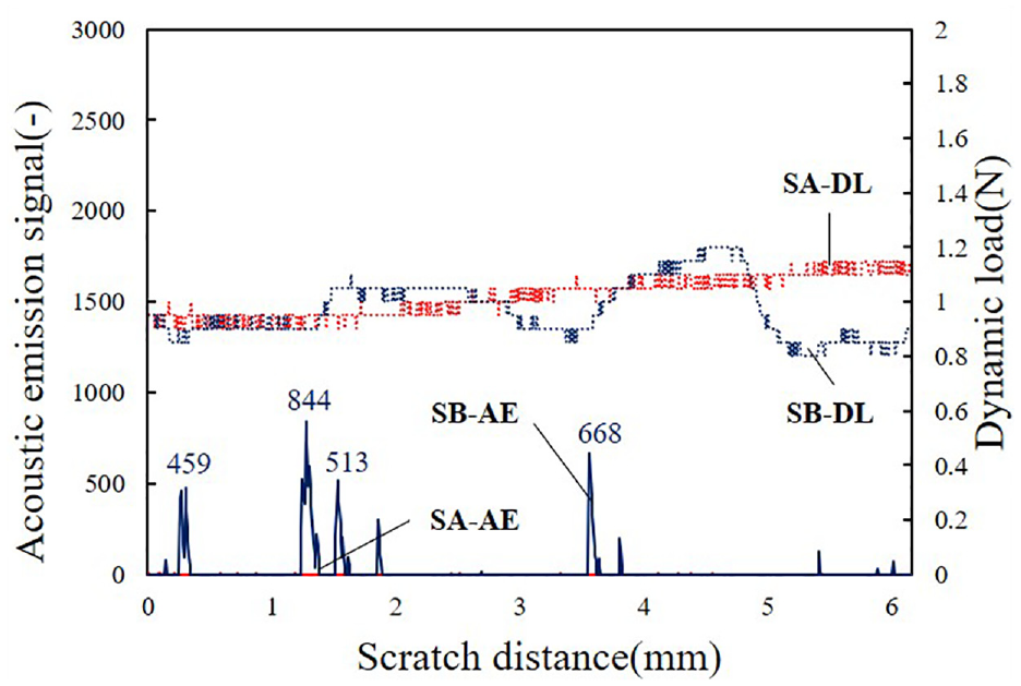
From Figures 5(a) and 8(b) and (d), it can be seen that when the indentation load in the SA direction is 1 N, when the indentation load is 3 N, the scratched surface of the material shows obvious damage. According to the analysis in Section “Material removal mechanism,” it can be seen that at this time, the material is broken with Silicon Carbide matrix fracture, interface debonding, and few carbon fibers show a shear fracture. In the SB direction, it can be seen from Figure 5(b) that the material scratches become wider when the scratching distance reaches about 3 mm, and the material scratches also become wider when the scratching distance is about 6 mm. This is consistent with the sudden change of the acoustic emission signal and the force signal in Figure 12. Combined with Section “Material removal mechanism,” it can be judged that the material damage here is relatively serious, the Cf/SiC shows a delamination by massive interface debonding and fiber fracture of bending features.
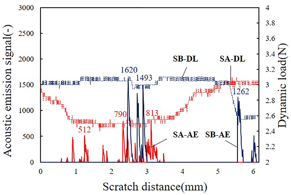
Acoustic emission signal and dynamic load with indentation load of 3 N.
From Figure 5(a), it can be seen that there is no significant material damage at 1 mm of the material in the SA direction, which is consistent with the acoustic emission signal remaining relatively stable with the force signal in Figure 13. But when the scratching distance continues to increase, there are large fluctuations in the acoustic emission signal and force signal. Combining Figure 8(c) and (e), it can be seen that compared with the scratch when the indentation load is 3 N, the scratch is wider and the material damage is more serious under this process parameter. According to the analysis in Section “Material removal mechanism,” the fiber shows severe damage of fracture debris, together with mix interface fracture of debonding and phase fracture. It can be seen from Figure 5(b) that when the SB direction is scratched, the material surface is damaged from the scratch, and the material damage near the scratch is extremely serious, which can be seen from the sharp fluctuations of the acoustic emission signal and the force signal in Figure 13 The situation reflects. Combined with the analysis in Section “Material removal mechanism,” it can be seen that under this scratching parameter, the damage situation is extremely complicated, and both the fiber and the interface are in a serious fracture state. Moreover, both the fiber and interface is under severe rupture with multiple fracture modes.
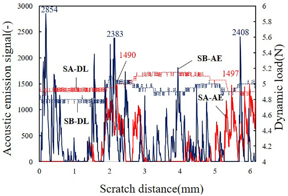
Acoustic emission signal and dynamic load with indentation load of 5 N.
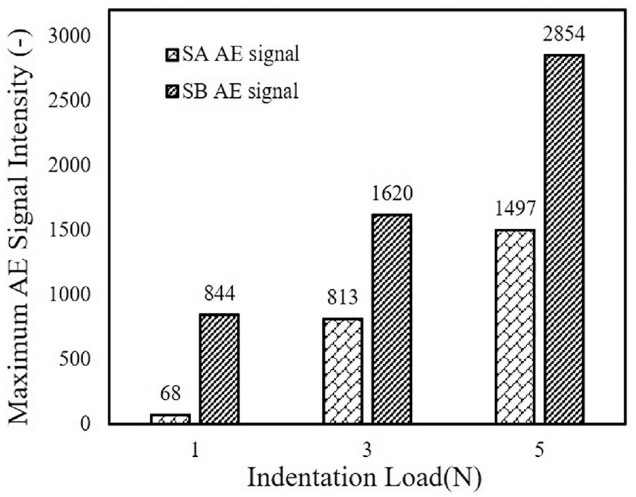
In general, the dynamic load measured in each scratching test fluctuates slightly around the indentation load, and the dynamic load in the SA direction is more stable than that in the SB direction, which indicates that the strength in the SA direction is higher. It can also be seen intuitively from Figure 5 that the surface of the material in the SA direction is smoother than that in the SB direction. And it can be seen from the acoustic emission signals measured under various parameters in Figure 14 that the acoustic emission signals of each test are extremely uneven. As the indentation load increases, the intensity of the acoustic emission signal increases significantly, and the fluctuation of the acoustic emission signal becomes more severe. Combining Figures 5, 8, and 9, it can be seen that as the indentation load increases, the damage to the material surface becomes more serious. It is worth noting that, as shown in Figure 12, in the scratching test with an indentation load of 3 N and SB direction, the dynamic load suddenly occurred in the final stage of the scratching test, and the value dropped significantly. This phenomenon may be caused by the overall fracture of this part of the matrix.
Acoustic emission signal under different indentation load.
Conclusions
Typical heterogeneous structure makes the Cf/SiC composites difficult to be removed at a desirable quality and efficiency. This paper is devoted to investigate the material’s mechanical response and removal mechanism by static single grit scratching method. The scratching force and acoustic emission signals, together with the groove topography, were measured to reveal the removal characteristics. The results show that the overall dynamic load of each scratching test fluctuates little around the preset load and the acoustic emission signal was extremely uneven for each test. The AE intensity increased significantly as the indentation load increased, and the peak value appeared more obvious and higher with the increase of indentation load.
Moreover, the groove depths and widths increase with the elevation of indentation load, accompanying with an increasingly severe surface damage and extended groove. When it is scratched in SA direction, the crack is first propagated at the tip of indenter along the normal and scratched direction, accompanied by grit extrusion along moving direction, shear removal along normal direction. In the SB scratched direction, the cracks are produced at a more severe intensity for the lower transverse strength. The cracks are generally propagated along the fiber direction with interface failure, also perpendicular bending fracture failure.
Footnotes
Appendix
Declaration of conflicting interests
The author(s) declared no potential conflicts of interest with respect to the research, authorship, and/or publication of this article.
Funding
The author(s) disclosed receipt of the following financial support for the research, authorship, and/or publication of this article: This work is supported in by the National Natural Science Foundation of China (No.52005098) and the Shanghai Natural Science Foundation (22ZR1402400). The authors wish to record their gratitude for the generous supports.