
Abstract
The present work is an attempt to model the components of specific grinding energy in a pragmatic manner. This work explores the contribution of specific energy constituents such as shearing, primary rubbing, secondary rubbing, and ploughing energy while grinding Inconel 718 (IN-718) superalloy. Specific shearing energy has been calculated using the dynamic yield strength of IN-718 as obtained by adopting the Johnson–Cook material model. Specific rubbing energy has been estimated using real contact length measured experimentally. Rubbing grit density has been estimated by considering grinding infeed, grit size, wheel structure, and work material hardness unlike the previous models, where it was mostly taken as a constant value. Single grit grinding experiments have been performed with 36 and 20 mesh size single alumina grits to obtain the insight of ductile flow in IN-718 grinding. These experiments have been conducted at grinding speeds of 5, 10, and 15 m/s using vacuum brazed single alumina grit shank fitted into aluminium make dummy grinding wheel. Specific ploughing energy has been estimated after suitably apportioning the tangential forces as obtained from single grit grinding. Two-dimensional study of the scratch profiles has been performed using a compound microscope to investigate plausible ploughing mechanisms of IN-718. The present studies indicate that at lower infeeds, micro-fracturing of alumina grits is more recurrent, whereas wear flattening is more common at higher infeed. The higher pile-up ratio at lower infeed signifies more ploughing resulting into inefficient cutting causing more energy consumption. The micro-fracturing of single alumina grit while scratching has also been observed. The present model for specific grinding energy is an improved version of earlier energy models as it incorporates variables which are much closer to the actual grinding conditions.
Keywords
Introduction
Grinding is an energy intensive secondary manufacturing process and is becoming one of the most popular manufacturing choices, comprising about 25% of the total machining processes. 1 The specific energy requirement in grinding is about one order or two orders of magnitude higher than other conventional metal cutting operations. The high requirement of specific energy while grinding makes the process more prone to surface oxidation of the ground product and causes significant wheel wear. 2 Thus, the precise estimation of the specific energy consumption is essential to accurately determine the power rating of the motor used for the grinding machine tool. Undoubtedly, this estimation becomes more relevant in the case of designing and prescribing the appropriate cooling and lubricating accessories to safeguard the ground surface from acute thermal exposure. The precise estimation of the energy expended while grinding can be made through a better understanding of the basic grinding mechanics. Grinding process resembles a scratching process. Researchers have also named grinding process as a multi-scratching process induced by the numerous hard abrasive grits.1,3 Hence, single grit scratching appears to be a unit event of a grinding process that needs to be investigated methodically to comprehend the possible grinding mechanisms. 4 Takenaka 5 was the first researcher who performed single grit grinding over a metallic workpiece.
Grinding is a complex and dynamic process where some important phenomena occur, which consumes a substantial amount of energy. 6 The important energy consumers in a grinding process can be listed as follows: 7
Chip formation due to shearing – chip formation due to shearing by the micro-cutting action of the hard abrasive grits;
Primary rubbing – rubbing between the grit tip and the work material;
Secondary rubbing – rubbing along the cutting edge between the abrasive grits and the work material over the entire cutting length;
Ploughing (ductile flow) – sideways displacement of the work material by the abrasive grits of undefined shapes with irregular cutting edges;
Wear flat rubbing – friction between the wear flat developed on the abrasive grit and the work material;
Friction between the loaded swarf and work material – friction between the loaded chip particles lodged at the inter-grit spacing and the work material;
Friction between the work material and the bond material;
Removal of thermo-mechanical micro-weldments between the loaded chips and workpiece and also between the grit tip and workpiece;
Removal of redeposited chip particles from the ground work surface.
Ghosh et al. 8 categorised the above-mentioned energy consumers into two broad segments. The chip formation due to shearing, primary rubbing, secondary rubbing, and ploughing (i.e. from 1 to 4) was clubbed in one group and was named as primary energy consumers in grinding. The remaining energy consumers (i.e. from 6 to 9) were placed in another group and named as secondary energy consumers. The researchers pointed explicitly that primary energy consumers are relevant in all types of grinding operations, whereas secondary energy consumers are significant only in longer duration grinding.
Superalloys are the high-performance advanced materials especially suitable for high temperature, high corrosion and also for working conditions which involve intense fluctuating stresses applications. 9 These alloys are widely used in making important components such as turbine blades, exhaust valves, nozzles, and combustion chambers of gas turbines to be used particularly in adverse working conditions. The usage of superalloys started from the late 1940s. 10 Inconel 718 (IN-718), an important Ni-based superalloy invented in the 1950s, covers up roughly half of the total superalloys in production and demand. 11 Its broad industrial acceptability is due to its high hot strength, high creep resistance, and high corrosion resistance.12–14 High strength, severe strain hardening, and low thermal conductivity of IN-718 make it a difficult-to-grind material (DTG). 15 Therefore, to improve its grindability and for proper selection of grinding parameters and metal working fluids, it becomes essential to estimate the specific grinding energy requirement accurately. Due to the ever increasing engineering applications of IN-718 superalloy, the present work considered this superalloy for estimation of specific grinding energy requirement.
State-of-the-art work related to specific grinding energy modelling and single grit grinding
The specific grinding energy also known as specific energy is a fundamental parameter for characterising the grinding process. It is defined as the energy expended per unit volume of material removal. 16 Its magnitude directly conveys the reflection of dominant mechanisms of abrasive work surface interactions. The specific energy is widely used as an inverse measure of the grinding efficiency. 17 In grinding of metallic materials, specific energy is modelled as the sum of shearing, rubbing, and ploughing components. A small number of theoretical and experimental works related to estimation of specific energy modelling in grinding process have been found in the available literature. First, Ghosh et al. 8 had presented a classic approach to estimate the different components of specific grinding energy. The estimation of total specific grinding energy was carried out considering the primary energy consumers in high efficiency deep grinding (HEDG) of bearing steel. They proposed a semi-empirical model to estimate the specific grinding energy and the same has been validated with the experimental results obtained by HEDG of bearing steel using cubic boron nitride (cBN) grinding wheel. Furthermore, Singh et al. 18 proposed and validated the model by performing the single grit scratch test using single point diamond dresser inserted in a dummy grinding wheel. They validated the results in case of two materials of exactly different natures, a ductile mild steel, and another hard conductive ceramic. Based on the experimental results, they presented the regression models to predict the specific energy components and had shown the predicted model values to be very close to the experimental ones. Öpöz and Chen 19 presented some investigations into single cBN grit grinding on EN24T steel. They critically investigated single grit scratching in terms of pile-up ratio, chip removal strength, and effective grit engage ratio. They studied the intricate mechanisms during single grit scratches and opined that the material removal is more prominent at the grit entrance side of the scratch compared with the grit exit side. In another research article, Öpöz and Chen 20 used cBN grits of mesh size 40/50 to produce scratches on IN-718. They glued the single cBN grain over the steel shank using Loctite super glue and conducted scratching at wheel peripheral speed of 8.37 m/s. Based on their experiments, they studied the material removal pattern of IN-718 at entrance to be shearing, whereas on exit side pile-up appears to be more prominent. The cBN grit dislodgement due to the limited adhesive strength of super glue was one of the main constraints in conductance of single grit scratch tests. Tian et al. 21 used regular diamond-shaped 30/40 mesh size single grit brazed on a tool holder to investigate the effect of grinding speed in material removal in grinding of GH4169 alloy. The speed effect was studied through analysing the variations in grinding forces, chip formation, and pile-up ratio. Based on their observations, they pointed that strain hardening dominates over thermal softening up to a grinding speed of 100 m/s, whereas beyond 100 m/s reversal of this phenomenon occurred. Azizi and Mohamadyari 22 modelled and simulated the grinding forces for single grit scratching on Inconel 738. They incorporated the influence of active grit counts over the grinding forces. According to them, slopes of the cutting edges are more influential than the number of cutting edges for grinding force simulation. Aurich and Steffes 23 conducted single grit scratch tests using cBN grit on AISI 4140H heat treated steel. They used an indexable insert onto which the single grain was galvanically bonded. Mainly, they focused on capturing the effect of different grit shapes in elastic–plastic material deformation during the single grit grinding. Based on their findings, they opined that the shape of the single grain scratches is the reflection of the grains shape. Doman et al. 24 performed finite element (FE) simulation of the rubbing and ploughing phases considering spherical indenters. They performed single-grain grinding using a scratch test setup. The measured forces were compared to the FE predicted and found to be in good agreement. Previously, many of the researchers have used shaped tools of known geometry, diamond stylus, diamond indenter, conical indenter, and spherical tool in making the single grit scratching to investigate the abrasive grit–workpiece interaction at micron level.18,24–27 However, such scratches significantly differ from the scratches obtained by actual grits during grinding.
Literature gap and outline of the work
Based on the above-cited literature, it can be seen that a little amount of research work related to the modelling and validation of specific grinding energy is present. Many research works focussed on the material flow pattern through scratch tests using either diamond indenter, spherical tool, and form tool instead of using an actual single grit.8,18,24–26 These shaped tools make the scratching easy, but the groove formed varies widely from a groove formed by an actual single grit grinding. Few works related to single grit grinding of IN-718 using superabrasive grits have been reported. Many of the researchers glued the grit over the shank using super glue which has limited adhesive strength.19,20 Often, this lower adhesive strength causes dislodging of the grit while performing the single grit scratch tests. Second, in almost all cited works, the authors have taken fixed values of rubbing grit per unit area (rubbing grit density) while calculating the specific rubbing energy components. However, in real practice, the variations in grinding parameters significantly influence the rubbing grit density. In earlier research works, while estimating the contact area, geometric contact length has been mostly considered, whereas the actual contact length significantly differs from the geometric contact length. 28 Additionally, many researchers took half of the tangential forces in the estimation of specific ploughing energy ignoring its dependence on grinding infeeds. 18 Therefore, the current work attempts to overcome those shortcomings by establishing a more realistic specific grinding energy model. The rubbing grit density has been calculated incorporating the important grinding variables such as grit size, wheel structure, average rake angle, and hardness of the work material. Moreover, unlike previous work, the proposed model considers the actual contact length rather the geometric contact length in the calculation of rubbing energy components. Two different sized alumina grits (#36 and #20 mesh size) have been brazed over the steel shanks. The vacuum brazed grits have much higher adhesive strength compared to the super glued grits used by some researchers. 20 The purpose of single grit scratch tests is to replicate and examine the actual behaviour of IN-718 deformation with single alumina grit. This investigation can be seen as a primitive phenomenon replicating the exact grinding process. Second, the grinding wheel speed (5, 10, and 15 m/s) used is similar to the actual wheel speed in case of surface grinding operation using the conventional abrasive wheel. The nature of plastic deformation has been studied under 36 and 20 mesh size alumina grits which seem to substantially quantify the dependence of material pile-up and ploughing with varying grit sizes. More importantly, based on the preliminary studies, measured tangential forces have been apportioned at different infeeds. The groove profilograms generated from the single grit experiments have been investigated using an advanced and high-resolution compound microscope. Scanning electron microscopy (SEM) study of the scratched surfaces has been performed to investigate the surface phenomena. In the end, the total specific grinding energy model in dry grinding of IN-718 has been developed using the experimental findings.
Experimental details and procedure
In this work, the dynamic behaviour of IN-718 has been captured using Johnson–Cook (JC) material model. Furthermore, single alumina grits have been brazed in vacuum using active braze alloy (ABA) over steel shanks. These brazed shanks have been further used in conducting single grit scratching/grinding. The number of experimental runs has been decided by adopting Box–Behnken experimental design which is based on the fundamentals of response surface methodology (RSM). The upcoming section elaborates the complete details of estimating the work material dynamic behaviour, grinding wheel, grit selection, and discussions related to the estimation of the different components of specific grinding energy. It also elaborates the methodology adopted for vacuum brazing of alumina grit and the subsequent procedure followed in single grit grinding.
Estimation of dynamic behaviour of IN-718
IN-718 exhibits dynamic behaviour in grinding due to its severe strain hardening nature. 12 In grinding, strain rate is much higher as compared to other machining processes, and shear stress increases with increase in strain rate. In this work, JC model has been used for estimating the yield stress for IN-718 at high strain rates. The JC model 29 incorporating the isotropic hardening of IN-718 has the form given below
where
where
The value of the nominal shear angle has been quantified using the relation
where

Equations (2)–(4) have been used to calculate
Selection of suitable abrasive grit
The prime focus of the present work is an improvement in grinding process effectiveness through cost and time reduction. A comprehensive experimental study was conducted by the authors to find the best-suited conventional abrasive wheel for IN-718 grinding, and consequently, it was concluded that alumina wheel appears to be the best choice. 33 Thus, alumina has been selected as the grit material for performing the single grit scratch tests. To investigate the effect of grit size on the specific grinding energy components, two different alumina grits of mesh sizes 36 and 20 have been selected in the present work.
Brazing of alumina grits over steel shanks
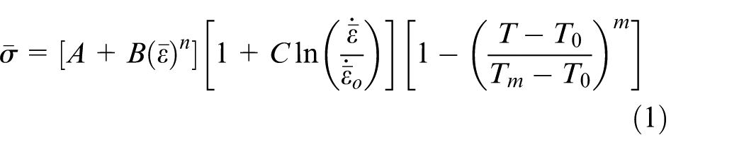
In single grit grinding tests, pull out of the grit during scratching is the main concern which happens due to the limited adhesive strength. Therefore, to overcome this limitation, the authors decided to braze the alumina grits, since brazing of the grits results in sufficient adhesive strength to sustain during scratching. Thus, in the present work, vacuum brazing technique using ABA has been adopted to braze alumina over steel shanks. ABA is a special silver–copper–titanium–based alloy which is specifically used in ceramic to metal brazing. Titanium (Ti)-based braze alloy is more suitable which has an excellent wetting property even to the ceramic surface due to the formation of titanium oxide (TiO) which has exquisite wettability nature. 34 Typically around 900 °C, Ti reacts with non-metal and forms oxide which has excellent wetting nature. In the present work, Ticusil has been used as ABA for brazing alumina grits over the steel shanks. A small indent with 0.5 mm drill bit has been made over the shanks so that the retention of the ABA can be ensured at elevated temperatures while performing brazing. The brazing has been conducted at 10−4 Torr vacuum level using vacuum brazing furnace. Figure 1 depicts the pictorial view of two steel shanks with included angle brazed with alumina grit used in single grit grinding experiments. Normally for conical grits, the rake angle can be taken as the half of the included angle as schematically shown in Figure 2. 16 Based on this analogy, in this work, an average of −45° as rake angle has been taken in the associated calculations.
A pictorial view of the steel shanks brazed with alumina grit of (a) 36 mesh size and (b) 20 mesh size.
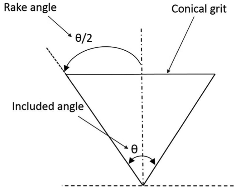
A schematic presentation of rake angle in conical shape grit.
Details of single grit grinding
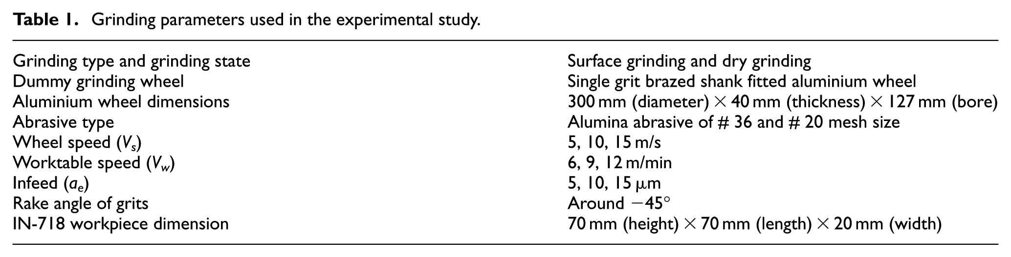
In this work, commercially available age-hardened IN-718 plates have been used for conducting single grit grinding experiments. All grinding experiments have been carried out in down grinding mode using a Chevalier Smart H1224II CNC surface grinder. Grinding forces have been measured online with a Kistler 9257B piezoelectric dynamometer. The detailed grinding kinematics, wheel type, wheel dimensions, and specimen size are listed in Table 1.
Grinding parameters used in the experimental study.
The single grit grinding has been performed using an in-house designed and manufactured setup as shown in Figure 3. Here, a single alumina brazed shank has been fitted into aluminium made dummy grinding wheel. The dummy wheel is equipped with spring and screw mechanism to hold the shank tightly. Before single grit grinding, the IN-718 surface was flattened and made smoother. Figures 4 and 5 show the photographic views of scratches made and the detailed nomenclature of the transverse cross-section of a typical scratch profile. Three- as well as two-dimensional scratch profiles have been captured using a microscope (Carl Zeiss, Germany) with the imaging resolution of 0.5 µm. Side flow of a ductile material is an important concern while estimating the energy consumption in grinding. This energy component can be illustrated with the help of material pile-up ratio which is defined as the ratio of total pile-up area (A1 + A2), and groove section area (Av) as depicted in Figure 5(b). 20 It postulates the elastic cum plastic deformation of the work material without actual cutting. Figure 5(a) shows the schematic of a typical scratch with geometrical parameters such as pile-up height (h), groove radius (r), and groove depth (e). 18
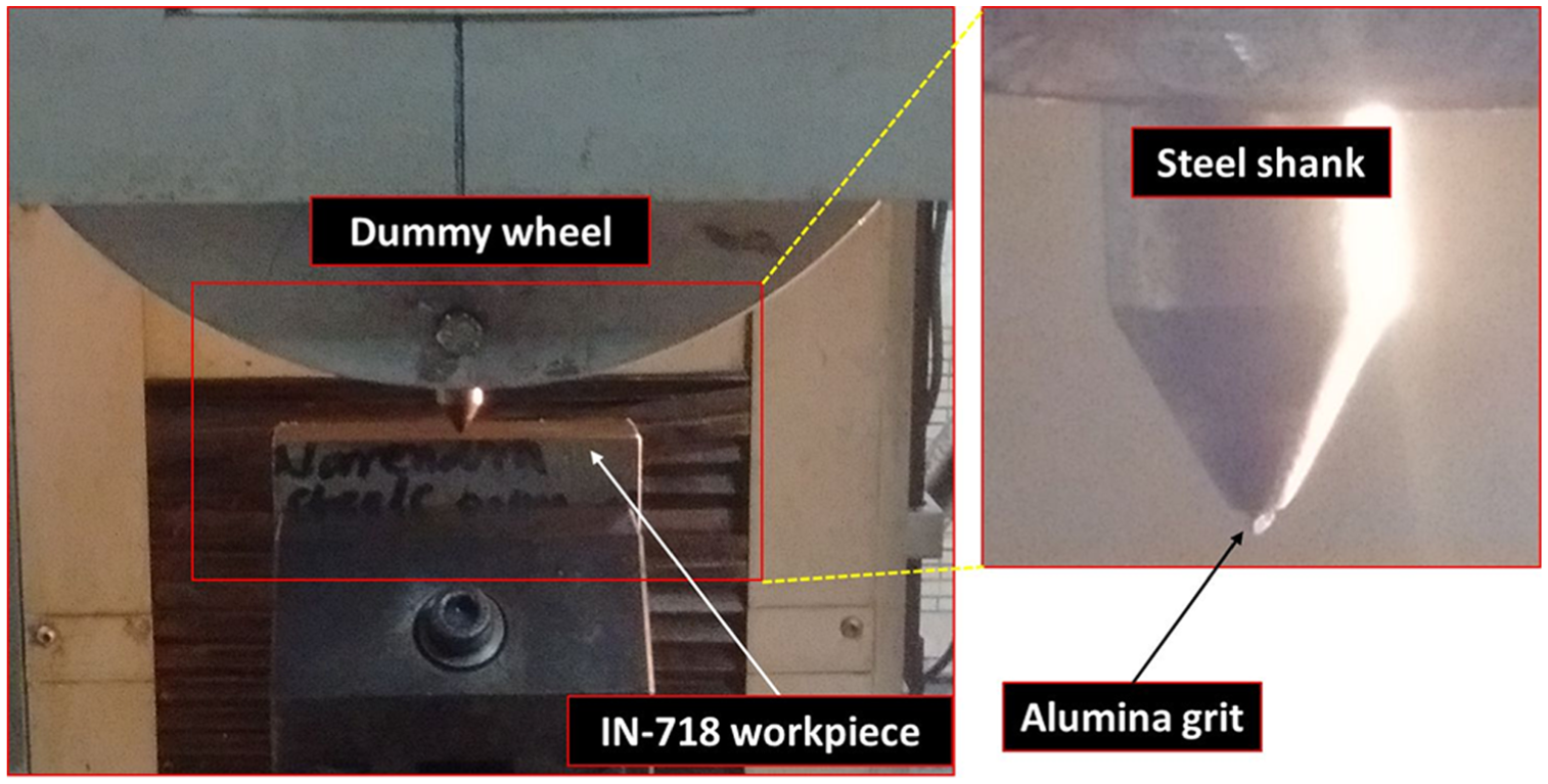
A pictorial view of the setup used for single grit grinding.
Single grit scratch images over IN-718 work samples.
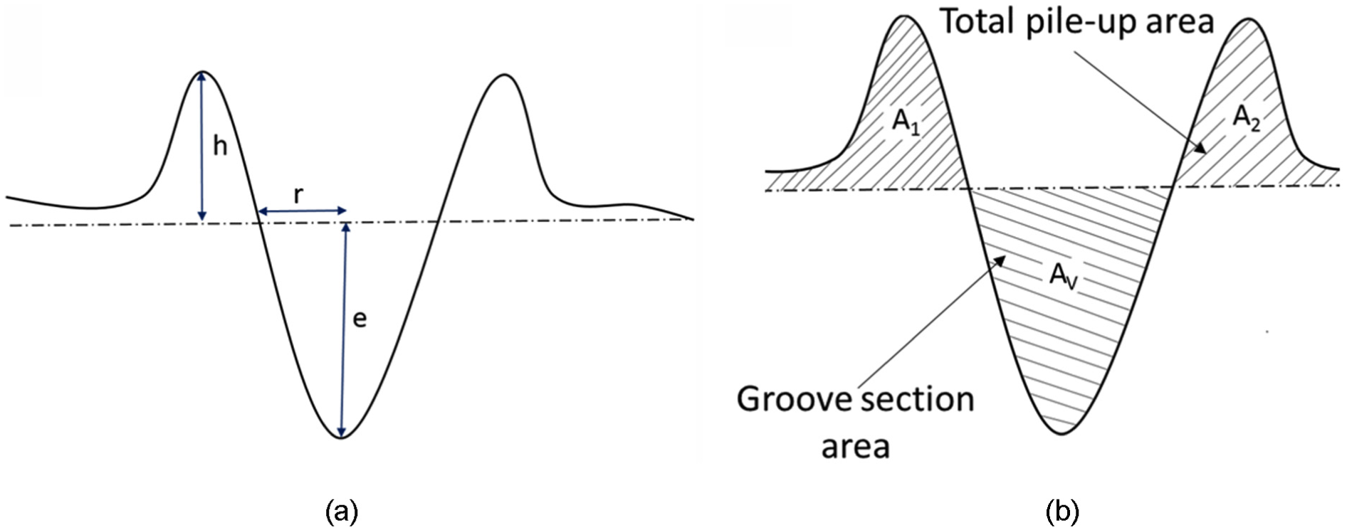
(a) Schematic of a groove and (b) groove transection indicating different areas.
Design of experiments for single grit grinding
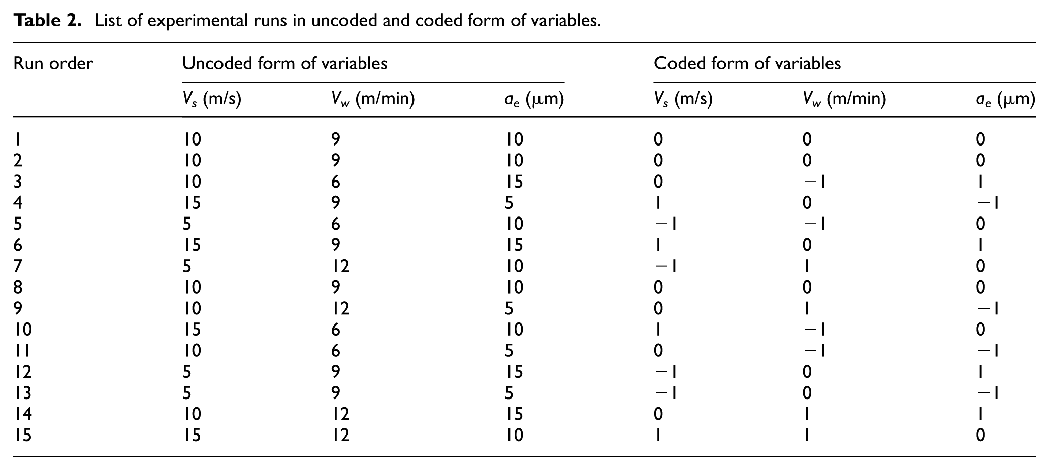
Experiments have been conducted to model the specific grinding energy components in terms of process parameters namely wheel speed, table speed, and infeed. Each of the process parameters has been considered at three different levels as given in Table 2. The number of experimental runs has been decided using Box–Behnken design. It is one of the best-suited design methodologies for three-factor and three-level design using the concept of RSM. 35 The number of experimental runs with coded and uncoded form of the variables is depicted in Table 2. The response variables measured were the normal (fn) and tangential (ft) forces per unit grit along with geometrical parameters such as total pile-up area, groove area, pile-up height, groove diameter, and groove depth.
List of experimental runs in uncoded and coded form of variables.
Estimation of specific grinding energy components
In metal grinding, components of primary energy consumers are more significant compared to other energy consuming components. 8 Therefore, this work is an endeavour to estimate the primary energy consumers accurately. A brief discussion about the components of primary energy consumers in grinding is as follows.
Specific shearing or chip formation energy (UShear)
The minimum energy expended per unit volume of material removal during grinding is known as specific shearing energy. This energy component can be estimated using classical theories on machining assuming perfectly sharp wheel using the following equation 18
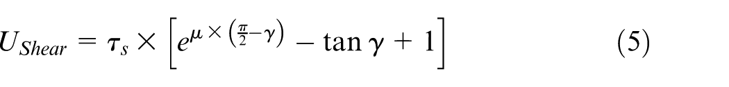
where
First, the value of
Specific primary rubbing energy (UPri_rub)
Rubbing is the phenomenon of sliding of the abrasive grits over the work surface without either shearing or displacing it. Normally, it occurs at the beginning of the grit-work surface engagement which can be estimated using the relation given as 18
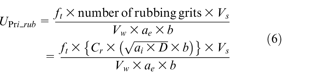
where
where
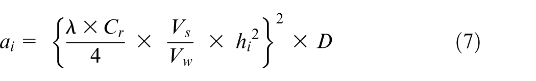
Specific secondary rubbing energy (USec_rub)
The phenomenon of secondary rubbing occurs between the grits and the workpiece due to high wedge angles of the abrasive grits along the entire grinding length of the work surface. 18 It can be estimated using the following analytical relation 18
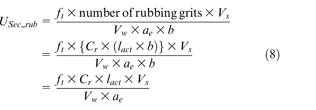
where
Specific ploughing energy (UPlo)
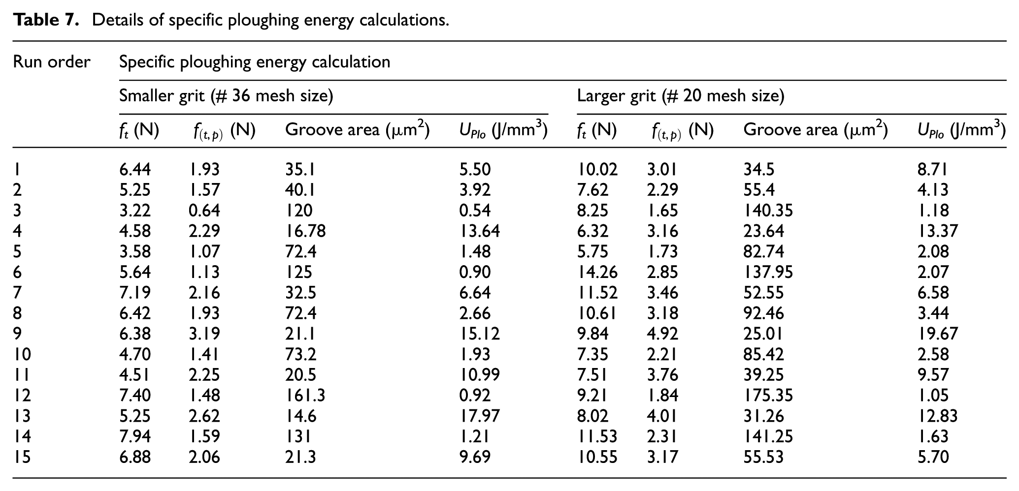
Ploughing is usually associated with side flow of the work material from the cutting path and takes the shape of ridges. 16 In the present work, this component has been evaluated using the two-dimensional surface profile of the displaced material during single grit grinding. The actual depth of cut has been measured using the two-dimensional profiles of the scratches at the deepest point. The specific ploughing energy can be estimated using the relation 18
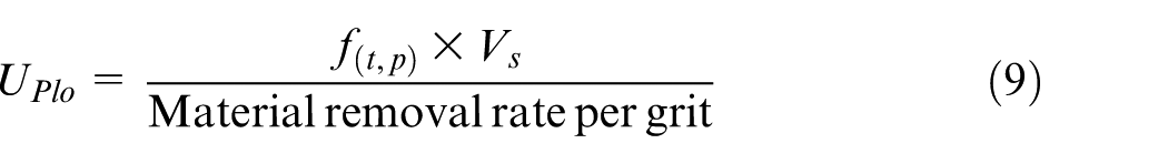
where
In single grit grinding, the total tangential force as obtained through measurement by a dynamometer arises mainly because of metal shearing, ploughing, and rubbing. Hence, in grinding operation,
Estimation of real contact length and rubbing grit density
The real length has a significant influence on the grinding forces, grinding zone temperature, elastic deflection, and surface integrity of the workpiece.36,37 In earlier work, the researchers used geometric contact length in the estimation of specific rubbing energy components. 18 However, in reality, the real contact length is a multiple of the geometric contact length. 38 Two-half slot method is used in this work to estimate the real contact length under different grinding conditions. In the present study, two half slots of width of 2 mm and depth of 0.2 mm are made over alumina grinding wheel maintaining a gap of 5 mm between the slots. Before making the slots, the grinding wheel was conditioned using a dressing lead of 25 mm/min and a dressing depth of 40 μm made in four passes.
In rubbing energy estimation, the estimation of the rubbing grit density becomes an important criterion which needs to be addressed accurately. In earlier work, the researchers primarily used a rough estimate of rubbing grit density mainly due to the complexities associated with its accurate estimation. In this work, the model developed by Setti et al. 39 has been adopted to estimate the rubbing grit density. This model relies on Rabinowicz’s abrasive wear model. Abrasive wear is the loss of material by the passage of hard particles over a surface. The proposed method, unlike the previous models, simultaneously takes care of the variations in infeed, abrasive grit sizes, and work material properties. In this model, based on the grinding wheel specification average load acting over individual grits has been estimated. The grit taking lesser load than the average load has been called as rubbing or simply contacting grits. These grits are not responsible for material shearing rather they simply slide over the work surface leading to rubbing.
Results and discussions
Specific shearing energy (UShear)
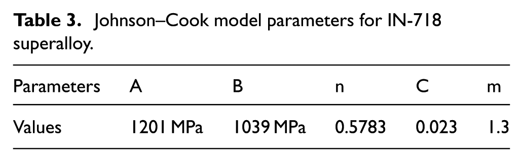
Figure 6 shows the load versus displacement, and true stress versus true strain diagram for IN-718 deduced from the compression test result. Some of the constants used in the model have been derived from a compression test of IN-718 specimen, and the remaining parameters of JC model have been taken from the similar findings of Wang et al. 29 They had shown the behaviour of C at different temperatures and strain rates and claimed that the error reduces to 1% at high strain rates. Table 3 summarises the JC model parameters used in this work for dynamic flow stress estimation of IN-718 superalloy. 29
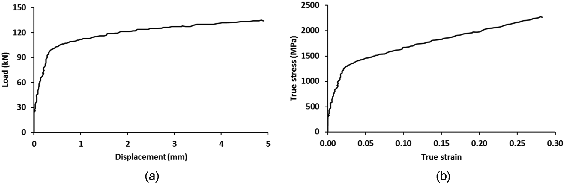
(a) Load versus displacement curve and (b) true stress versus true strain curve for IN-718.
Johnson–Cook model parameters for IN-718 superalloy.
IN-718 shows almost stable mechanical responses in machining up to a temperature limit of 700 °C.
12
Normally, in surface grinding of IN-718, the average temperature of the ground surface falls in the range of 1000 °C.
33
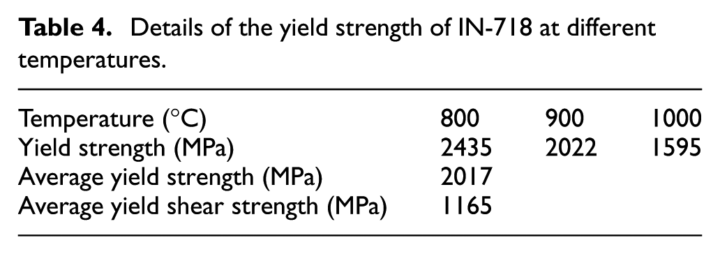
Therefore, in this work, the mean of yield strength values in between 800 °C, 900 °C, and 1000 °C has been taken in the calculation of UShear. Using JC model, the values of the yield strength at different temperatures have been estimated and are given in Table 4.
Details of the yield strength of IN-718 at different temperatures.
Specific primary rubbing energy (UPri_rub)
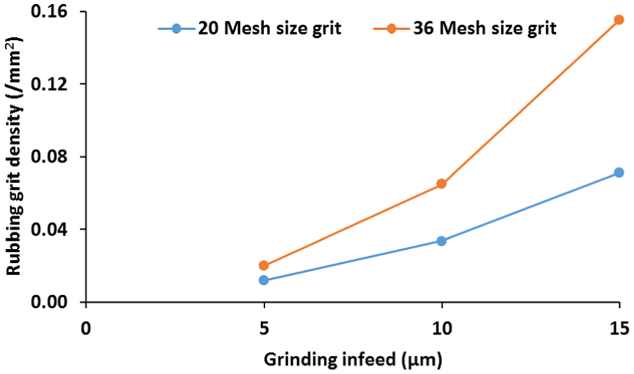
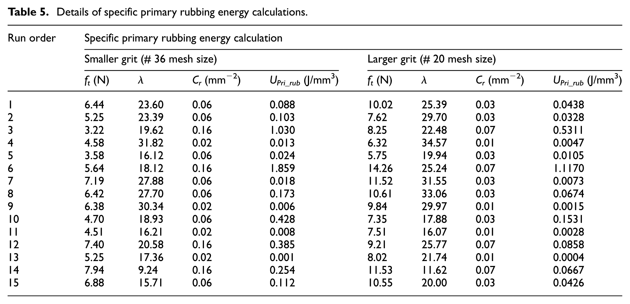
An accurate estimation of the rubbing grit density becomes important in the estimation of specific rubbing energy components. In the present work, it is estimated using the model developed by Setti et al. 39 The rubbing grit density for 30 and 20 mesh size grits at different infeed values have been calculated using the model developed by Setti et al. 39 and is shown in Figure 7. The rubbing grit density for 36 mesh size grit is slightly on the higher side and has an increasing trend with an increase in grinding infeed. Using the measured values of tangential forces, calculated rubbing grit density, and deduced values of λ as the ratio of the measured value of groove width and groove depth, the different values of UPri_rub at different grinding kinematic conditions have been calculated using equation (6) and are presented in Table 5.
Variation in rubbing grit density with grinding infeeds.
Details of specific primary rubbing energy calculations.
Specific secondary rubbing energy (USec_rub)
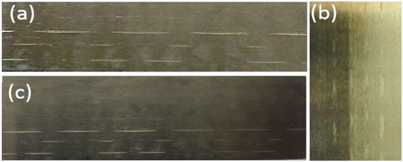
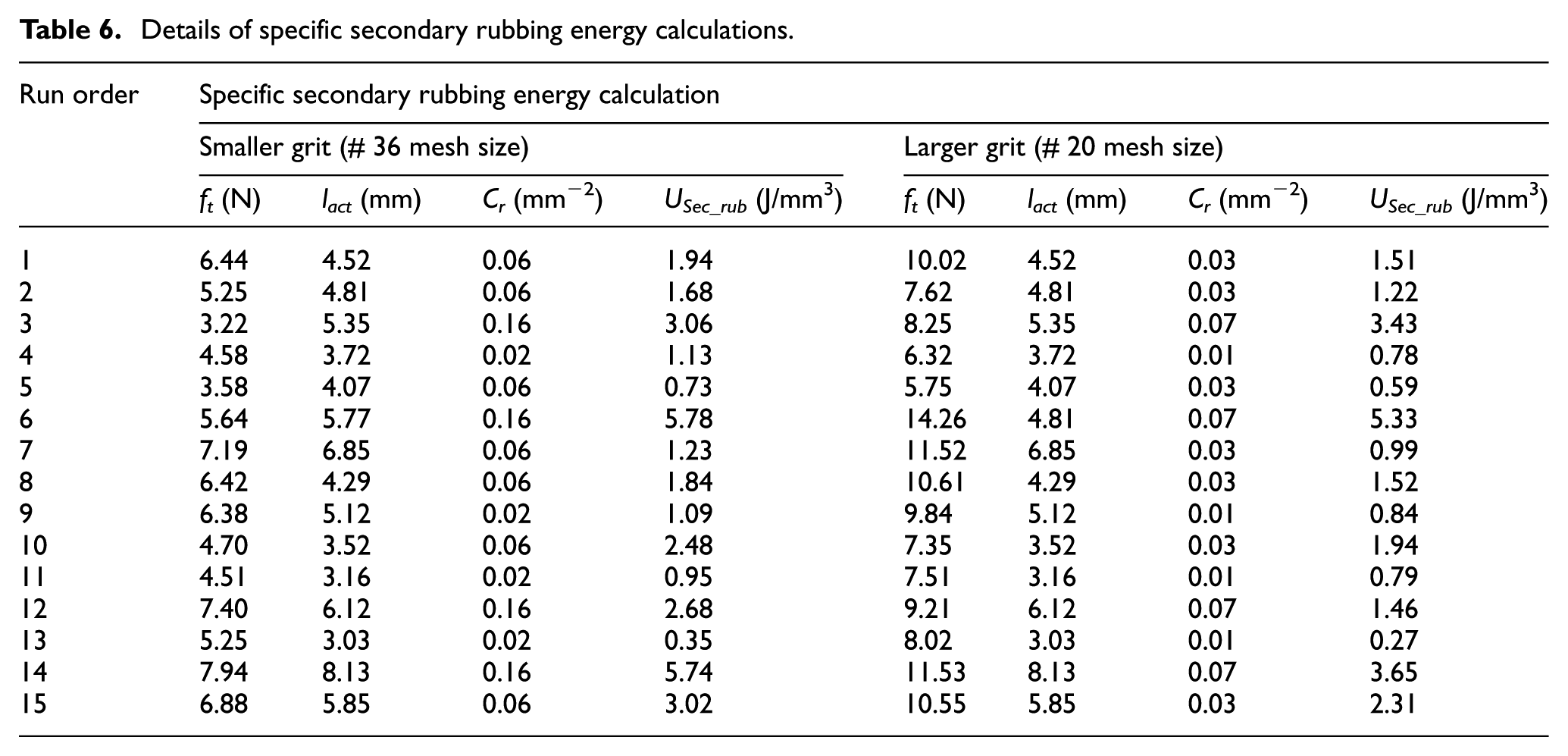
Secondary energy is an important and significant energy consumer in grinding process. Figure 8 shows the slotted alumina grinding wheel used for contact length experiments. Alternate patches of contact and non-contact of the grinding wheel over the IN-718 work surface can be clearly seen in Figure 8(b)–(d). Furthermore, using stereo zoom microscope (Carl Zeiss), these contact lengths have been measured and found to be much higher than the geometric contact lengths. Here, using the value of ft, Cr, and lact in equation (8), the component of USec_rub has been estimated. The estimated values of USec_rub at different grinding kinematics are listed in Table 6. From the listed values in the table, it is clearly seen that 36 mesh size grit yielded higher values of USec_rub as compared to 20 mesh size grit. It is mainly due to the larger value of rubbing grit density for 36 mesh size grit as compared to 20 mesh size grit.
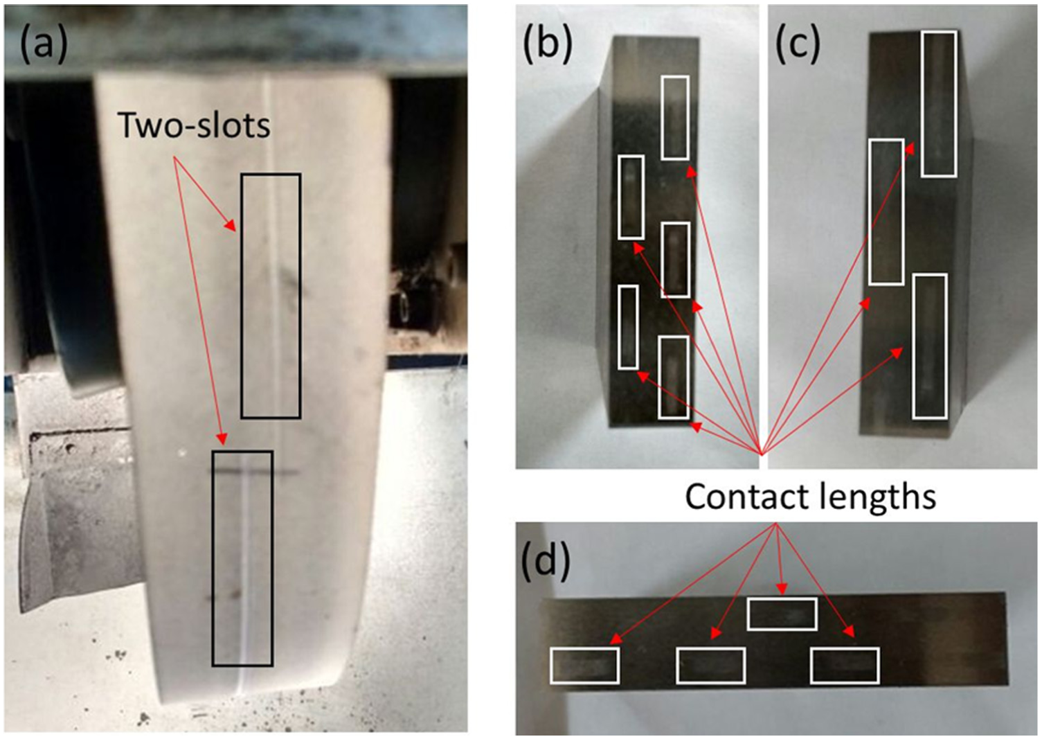
(a) Pictorial view of the slots on wheel surface and (b–d) patterns on IN-718 work surfaces after the first pass at different grinding kinematics.
Details of specific secondary rubbing energy calculations.
Specific ploughing energy (UPlo)
Specific ploughing energy is a significant contributor in specific grinding energy estimation, particularly for tough IN-718. Here, based on the scratch profilograms studies, at different infeeds, pile-up ratio for both grit sizes has been calculated. Pile-up ratio in case of 36 mesh size grit has been observed to be on the higher side compared to 20 mesh size grit (refer Figure 9) at lower infeed. Figure 9 reflects the inverse behaviour of pile-up ratio at higher infeeds for both grit sizes. Higher pile-up ratio at lower infeed signifies inefficient material cutting leading to more power consumption. It also signifies the sideways displacement of the work material after plastic deformation.
20
The pile-up of IN-718 is a consequence of the kinematic interaction between the grit and the work surface, which in turn depends on the process parameters. Indeed, higher material pile-up has been observed at higher grinding speed and lower infeed. It could be attributed to insufficient material strain rate eventually resulting in more material being displaced and therefore more material pile-up.
23
Here, the share of UPlo in UTotal has been found to be nearly 50%, 30%, and 20% at the infeed of 5, 10, and 15 μm, respectively. Therefore, UPlo for 5, 10, and 15 μm has been calculated incorporating modified
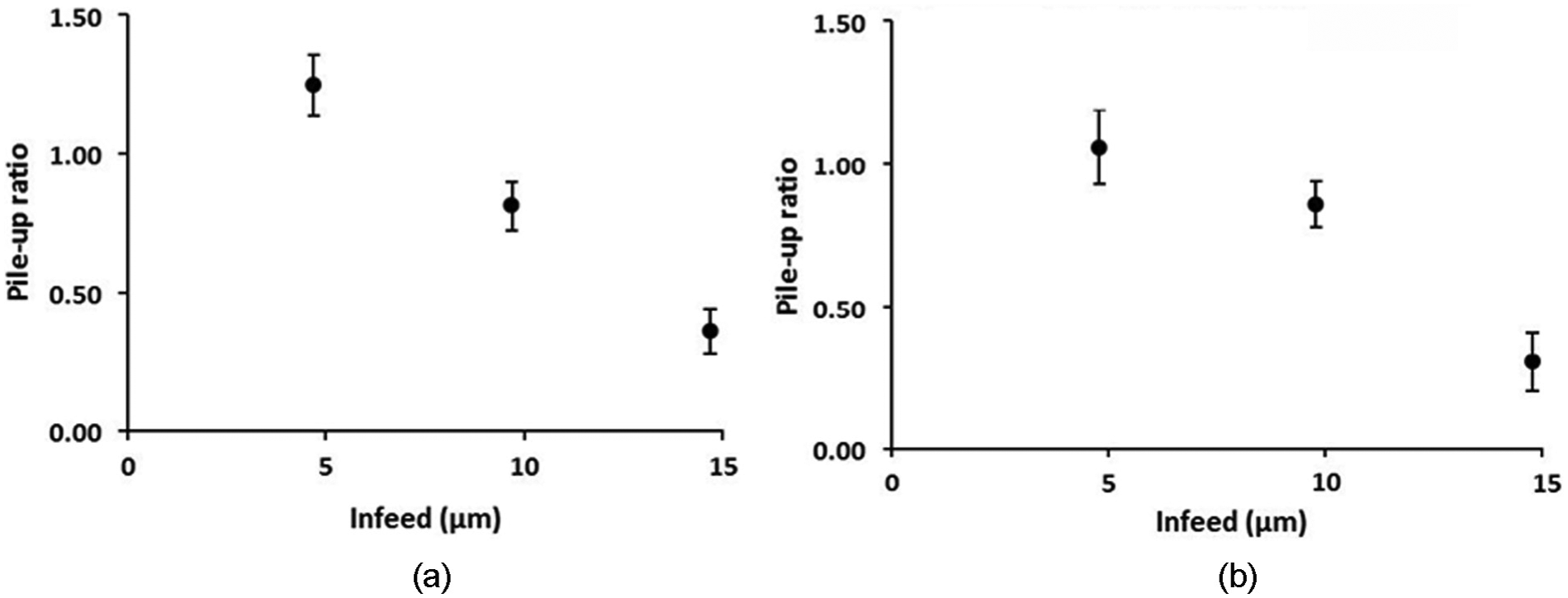
Pile-up ratio variations with grinding infeeds: (a) 36 mesh size grit and (b) 20 mesh size grit.
Details of specific ploughing energy calculations.
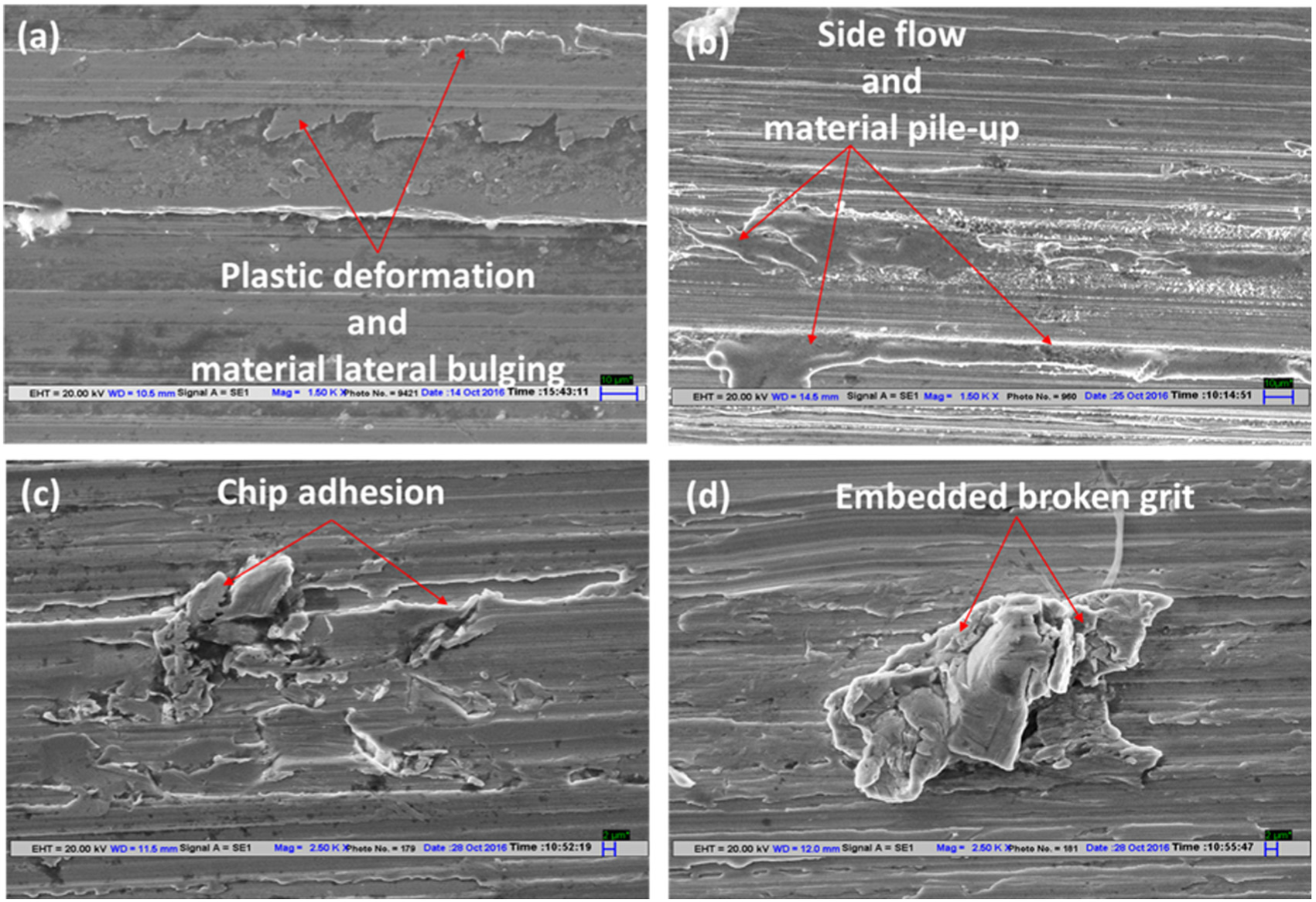
SEM observations of IN-718 samples ground with single alumina grit.
Micro-fracturing of abrasive grits during grinding operation is a very common and prominent phenomenon. Furthermore, it becomes more prominent with the highly friable alumina grit during grinding of tough IN-718. In this study, the analysis of the scratches reveals that the micro-fracturing is more common at lower infeed. The intensity of micro-fracturing diminishes with an increase in infeed, which is depicted in Figures 11 and 12. Such behaviour is exhibited because stress field intensifies over a relatively small grit tip area leading to the generation of micro-cracks. 4 Whereas, with an increase in infeed, the share of the area becomes larger compared to the increase in load and this eventually results in reduced micro-fracturing of the grain. At higher infeed, the grits are more prone to attritious wear leading to the formation of wear flats rather than generating multiple cutting edges. This possibility is well supported by the groove surface profiles shown in Figures 11(c) and 12(c). Possibly, the micro-fracturing phenomenon could be another possibility for the higher ploughing energy consumption at relatively lower infeeds.
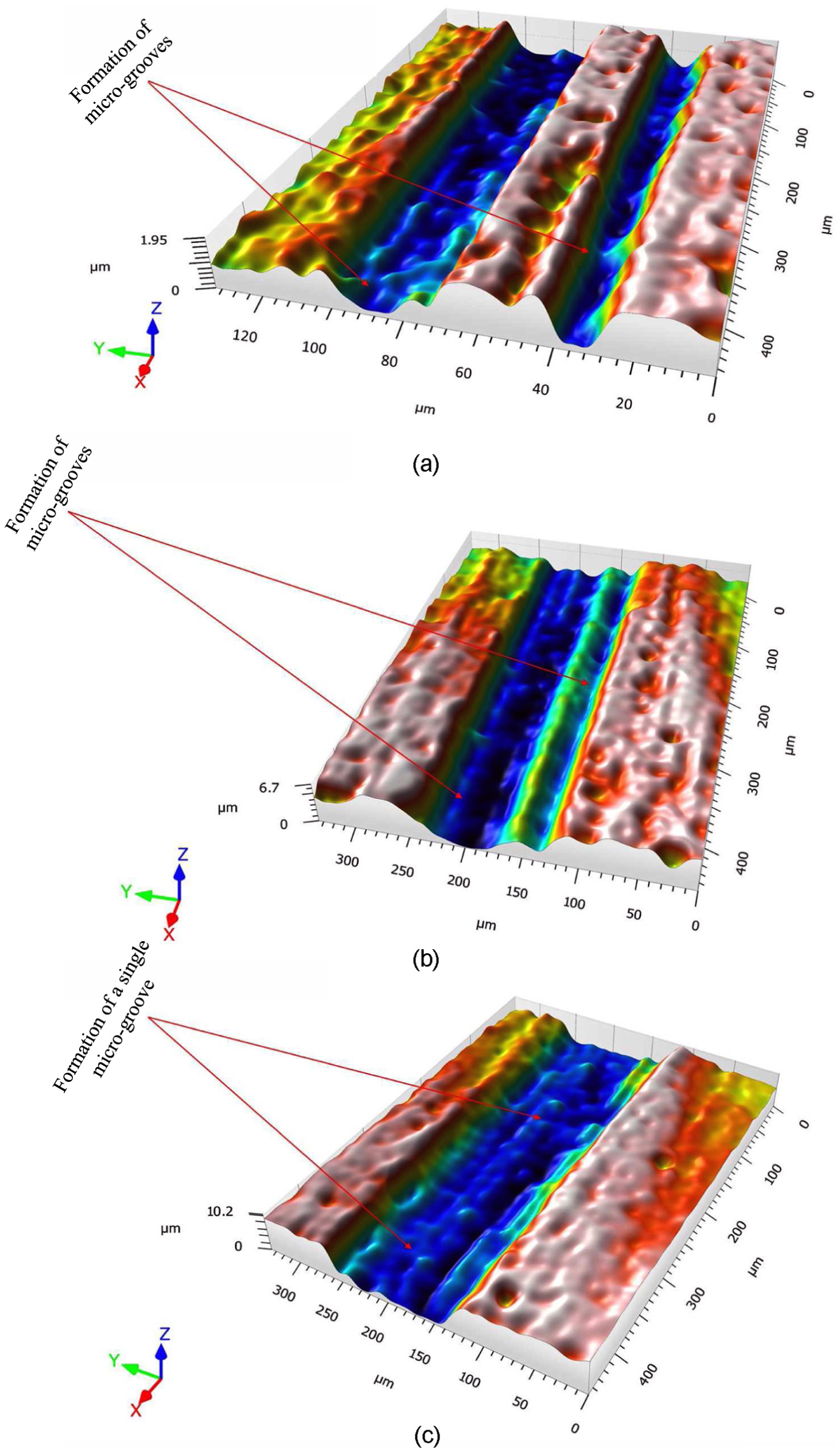
Three-dimensional grooves profile generated at different grinding infeeds: (a) formation of two micro-grooves separated by un-distorted work surface at 5 μm infeed, (b) formation of two micro-grooves at 10 μm infeed, and (c) formation of single micro-groove at 15 μm infeed.
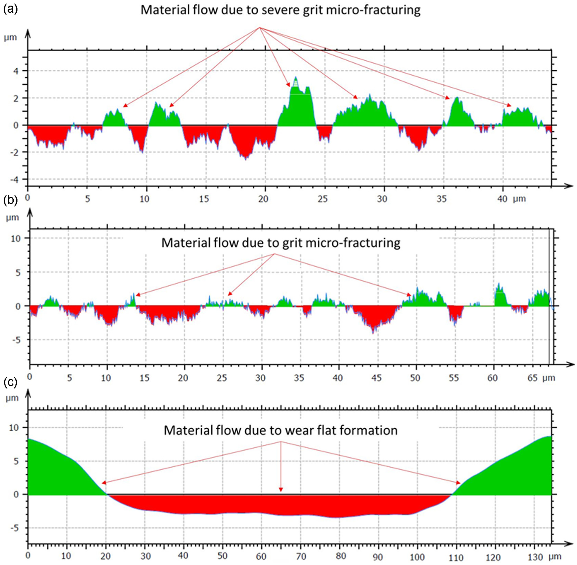
A view of a transverse cross-section of the scratches formed at grinding infeed of (a) 5 μm, (b) 10 μm, and (c) 15 μm.
Specific grinding energy (UTotal) comparison for two grit sizes
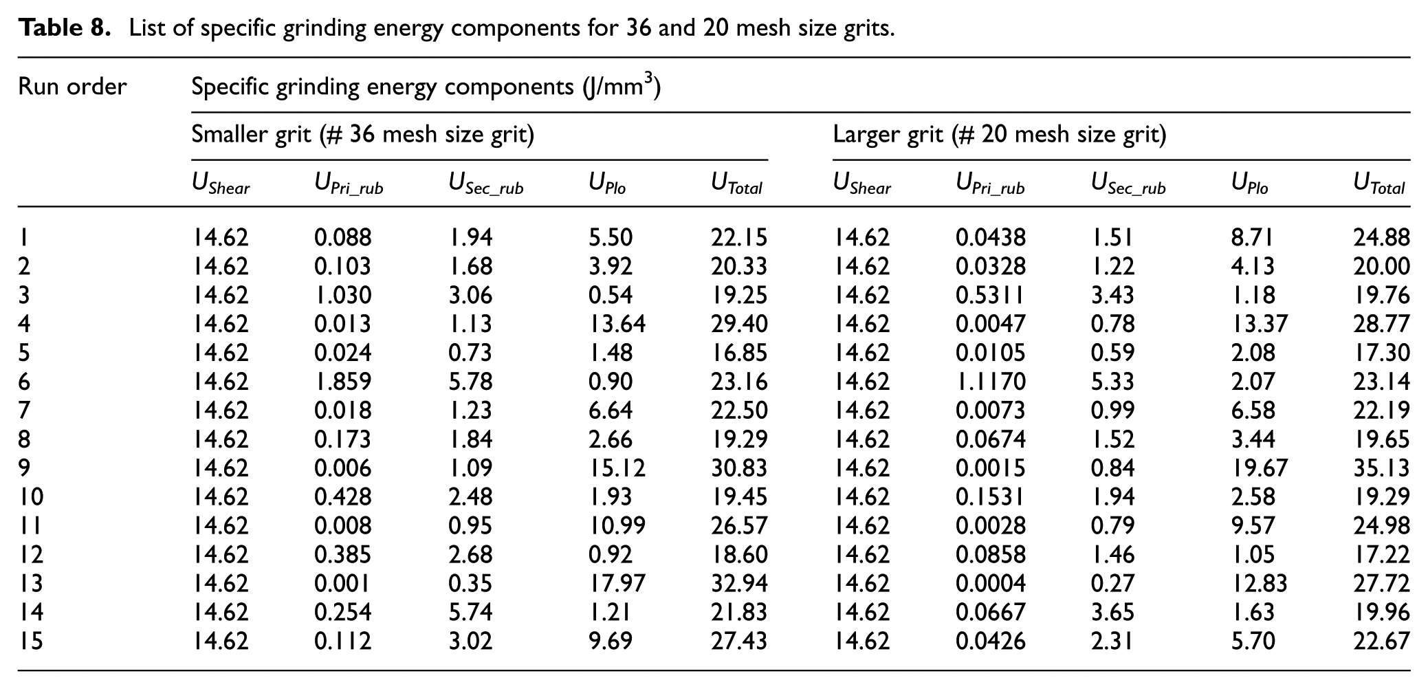
Figure 13 reveals the different components of specific grinding energy variation with grinding infeed at 15 m/s wheel speed and 9 m/min table speed for both grits. The magnitude of UShear has been found to be constant for both grit types and irrespective of the change in grinding kinematics. 16 The rubbing energy components are found to be consistently increasing with increase in infeed for both grits. It could be due to increase in rubbing grit density and tangential force values with increase in infeed. This observation is in line with the basics of the grinding principle. 36 Another important observation is the continuous increment in UPlo with a decrease in infeed. It can be explained with the argument that the role of the metal shearing is relatively small and decreases with the decline of grinding infeed. 36 Table 8 contains and summarises the numerical values of all components of specific grinding energy taken into account for both grit sizes. These tabulated values can be used to infer the relevant information about their individual contribution to the total grinding energy.
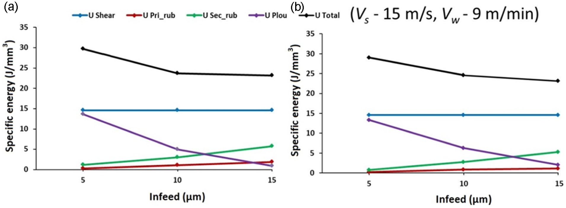
Variation in components of specific grinding energy: (a) 36 mesh size grit and (b) 20 mesh size grit.
List of specific grinding energy components for 36 and 20 mesh size grits.
Validation of the modelled specific grinding energy
The comparison between the actual and the predicted UTotal for both grit sizes has been presented in Figure 14. The figure depicts a close matching of the trend between the actual and the predicted values for both grits with reasonable scattering. Indeed, these scattering may be attributed to the in-process grit fracturing, wear flat formation, and change in shape of the grits during single grit grinding. Another prominent possibility can be due to the exclusion of secondary energy consumers. Formation and growth of continuous wear flats in grinding, friction between bond and workpiece, wheel loading, and redeposition of debris over the work surface are some of the secondary energy consumers.
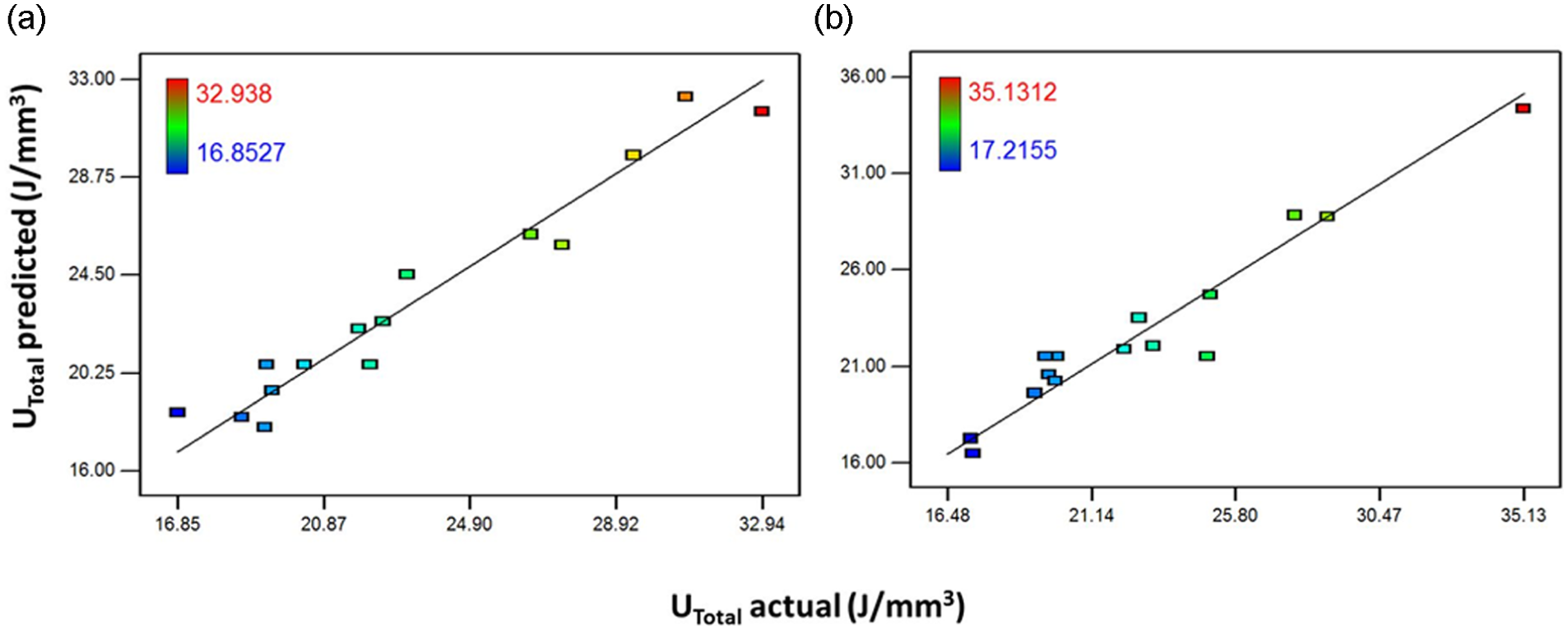
Comparison between the predicted and actual values of total specific grinding energy: (a) 36 mesh size grit and (b) 20 mesh size grit.
Conclusion
This work is a comprehensive attempt to investigate the fundamentals of metal cutting in grinding of IN-718. It has been explored deeply after performing single grit grinding using alumina grit brazed steel shanks. Specific shearing energy has been calculated by incorporating the dynamic property of IN-718. The rubbing components have been modelled realistically incorporating the real contact length and improved value of rubbing grit density. Specific ploughing energy has been estimated by incorporating the value of tangential force in ploughing after apportioning the tangential forces obtained from single grit grinding. The phenomenon of ploughing has been studied meticulously through two-dimensional investigations of the cross-section of the groove profiles. The major conclusions of this research work are listed as follows:
The dynamic yield strength of IN-718 has been estimated using JC model and found to be decreasing with increase in temperature beyond the threshold value of 700 °C, overriding the effect of work-hardening.
Specific shearing energy has been calculated using dynamic yield strength of IN-718. This energy is found to be independent of grit sizes and grinding kinematics.
Specific primary rubbing energy has been estimated employing rubbing grit density calculated using abrasive wear model. The contribution of this energy component is limited to 1.5% of total specific grinding energy.
In the estimation of secondary rubbing energy, along with improved rubbing grit density, actual contact length has been considered. It makes the proposed model more accurate and closer to the real grinding process. The proportion of specific secondary rubbing energy is up to 10.5% of total specific grinding energy. Its values are found to be increasing with increase in grinding infeed and grit mesh size.
The proportion of specific ploughing energy has been calculated considering an appropriate apportionment of tangential forces at different grinding infeeds. In this work, average tangential force in ploughing has been taken as 50%, 30%, and 20% of tangential forces at grinding infeeds of 5, 10, and 15 µm, respectively.
A substantial increase in the percentage of specific ploughing energy has been observed in the case of grinding at smaller infeed. This is primarily due to increased micro-splintering of grit resulting into a generation of multi-cutting edges leading to substantial increase in pile-up ratio at lower infeed.
Footnotes
Appendix 1
Acknowledgements
The authors would like to thank Dr Amitava Ghosh, Associate Professor – Department of Mechanical Engineering, IIT Madras for his support in conducting vacuum brazing of alumina grits. The support received by M/S Carl Zeiss (Bangalore) India Pvt. Ltd. in performing the three-dimensional profile studies of scratches is gratefully acknowledged. The support and guidance while conducting single grit grinding, SEM study from the staff of Central Research Facility (CRF), and Nanoscale Research Facility (NRF), IIT Delhi is thankfully recognised. The authors would like to acknowledge the help and support received from Dr Prashant Gudur, Mr Neeraj Carpenter, and Mr Pai.
Declaration of conflicting interests
The author(s) declared no potential conflicts of interest with respect to the research, authorship, and/or publication of this article.
Funding
The author(s) received no financial support for the research, authorship, and/or publication of this article.