
Abstract
Grinding is an essential gear finishing method. Grinding force analysis and prediction are critical to understand grinding mechanisms. By using a geometry model for gear form grinding and surface grinding mechanisms, a theoretical model was established to calculate the gear form grinding force. By considering the complete tooth depth engagement between tooth grooves and wheel profiles during form grinding, three segments of the involute, transition arc and tooth bottom line, which were included in complete tooth groove profiles, were analysed using the model. Contact relations among the normal grinding depth, wheel equivalent radius, wheel linear velocity and wheel profile were obtained. In addition, grinding experiments were outperformed on the basis of the single tooth, and the unknown coefficients of the form grinding force calculation model were acquired. The effects of the grinding depth, feed speed and grinding speed on grinding force were analysed using the grinding force model. The comparison of the predicted values of the form grinding force model with the experimental results, indicated that the relative errors of tangential and normal grinding forces are within ±10% and ±12%, respectively. The results confirmed the accuracy of gear form grinding force calculation model. These findings play a key role in parameter optimisation during gear form grinding.
Introduction
Gears are an essential transmission part, which is widely used in industries such as automobiles, construction machinery, aerospace and ships. High-precision gears can improve the transmission accuracy and stability and minimise vibration and shock-induced energy loss.1,2 Gear grinding is the process of tooth profile finishing of hardened gear parts and is commonly performed on the basis of rough machining of tooth profiles (such as hobbing and milling) and heat treatment. The finishing allowance is removed through grinding to further improve the gear accuracy and surface quality.3–5 Grinding force is the main parameter that characterises the basic laws of grinding. The resistance generated through the elastic and plastic deformation of gear materials and the friction force produced among abrasive grains, bonding agents and a gear surface are the sources of grinding force.6,7 The grinding force is closely associated with grinding surface quality, grinding specific energy and wheel durability, and is vital for energy consumption, heat generation and vibration during grinding process.8,9 Grinding force modelling helps in the study of material removal mechanisms and mechanical behaviours. 10
Numerous grinding force studies have focussed on grinding processes with simple kinematics and tool geometry, such as surface, external and internal grinding. Tang et al. 11 presented a surface grinding force model combined with abrasive machining theory. The effects of grinding machining parameters on the dynamic mechanical properties of metal cutting and on the friction coefficient between the workpiece surface and abrasive grain were comprehensively considered. To study surface grinding of SiCp/Al composites, Gu et al. 12 established a PSO-SVM predictive model for the multi-abrasive grinding force of silicon-carbide-particle-reinforced aluminium matrix composites according to big data analyses and machine learning. Cai et al. 13 developed a dynamic grinding force model for the peripheral grinding of carbide inserts with the help of a single-abrasive grain grinding force model. In this model, cross-segmental cutting and wear flat zones were analysed, and the effect of residual stress was emphasised. Fang et al. 14 reported an internal thread grinding force model by considering the thread helix angle and overlap effect of abrasive grains. In addition, the optimum normal force without pits can be obtained on the internal thread surface.
Similarities among the aforementioned grinding methods are as follows: the contour shape of the wheel width is parallel to the wheel axis, and the grinding contact zone between the workpiece surface and grinding wheel is regular. However, for form grinding with complex-shaped workpieces, the distribution of grinding parameters and effective diameter of the wheel along the normal segment of a workpiece profile are different, and the grinding load distribution is nonuniform. 15 Hence, the grinding force models of the aforementioned grinding methods are not suitable for complex form grinding. Miao et al. 16 used microcrystalline alumina abrasive wheels to form grind the turbine blade roots of a nickel-based superalloy, and analysed the comprehensive effects of the grinding parameters and root cross-segmental profile of workpieces on the grinding force. These studies are of considerable importance in the process optimisation of parts with complex profiles. Rausch et al. 17 proposed a prediction model for the grinding force of grinding free-formed surfaces based on the chip thickness. The grinding force model uses an ideal CSG particle shape and a geometric kinematics modelling method represented using a dexel model.
For the gear grinding of complex shapes, the commonly used grinding methods are generative grinding 18 and form grinding. Considering the constantly changing grinding contact conditions, Hübner et al. 19 proposed a simulation-based grinding force model for gear generative grinding. This model can be used to describe dynamic changes in the grinding process and optimise the process. Similarly, Guerrini et al. 20 proposed a new two-stage finite-element method for gear generative grinding. Real abrasive grain geometry obtained through computer tomography in a paper 21 was employed as the modelling basis. Furthermore, the simulation results of the grinding force of the single-abrasive grain grinding model were compared with the experimentally measured grinding force for grinding force prediction. Teixeira et al. 22 developed an alternative method for normal force modelling considering tool topography during gear grinding. Generative grinding depends on the generative motion of grinders, and the workpiece and grinding wheel are mutually enveloped to form an involute tooth profile. Thus, the grinding force model is established using point contact between the workpiece surface and grinding wheel. However, form grinding is conducted based on the engagement of the wheel form surface and tooth surface on both the sides of tooth grooves, and the grinding process is line contact. 23 For the nonlinear distribution of the tangential grinding force in gear form grinding, Yi et al.24,25 proposed an analytical model to calculate this force on the basis of the measured grinding power. However, the soft measurement method using grinding power is less accurate than a dynamometer. Wang 26 and Yang 27 have proposed grinding force models for form grinding the involute gear with microcrystal corundum grinding wheels. The effects of grinding parameters, the edge density of abrasive grains and the geometric parameters of gears on the grinding force were described. This study establishes the theoretical and experimental basis for selecting reasonable gear form grinding technology. However, during grinding, variations in the grinding parameters of each point on the involute tooth profile and the equivalent diameter of the grinding wheel were not considered.
During gear form grinding, differences in the curvature of each point on the involute of the tooth profile lead to variations in the grinding depth, wheel equivalent diameter and grinding speed of each point. Hence, on the grinding contact line, the grinding force constantly varies. Form grinding characterised by a large contact length with additional uneven stock must be eliminated along the profile line. 28 The risk of grinding burns is high in entire tooth groove grinding; thus, the form grinding force of the complete tooth depth engagement must be studied.
For complex gear form grinding, the present work deals mainly with the grinding force of involute segment, and the accurate prediction of the grinding force considering complete tooth depth engagement which has higher burn risk during grinding is limited. Different from existing studies, this paper analysed grinding force in detail on three segments of complete tooth groove profiles: involute, transition arc and tooth bottom line. By considering grinding force dynamic changes in involute gears during form grinding and the complete tooth height engagement between tooth grooves and the wheel profiles, a grinding force calculation model was established for gear form grinding. On the basis of the geometry model of gear form grinding, the contact relations among the normal grinding depth, wheel equivalent radius, wheel linear velocity and wheel profile were described. Additionally, the effects of grinding parameters on the grinding force were analysed by using the grinding force calculation model. The prediction results of the calculation model were compared with the experimental results to verify the accuracy of the grinding force model. The results are beneficial for optimising gear form grinding.
Geometry model of gear form grinding
During gear form grinding, after precise dressing, the wheel form surface is used as the grinding plane. The complete tooth depth engagement is formed between the wheel form surface and two sides of the tooth groove. Figure 1 illustrates a form grinding based on the grinding contact relation between the grinding wheel and gear for complete tooth depth engagement.
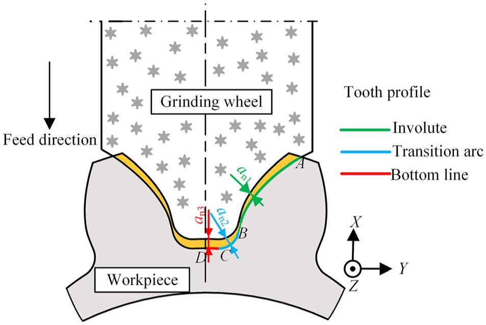
Gear form grinding in complete tooth depth engagement.
Figure 1 shows grinding contact between the tooth profile of the gear end face and wheel form surface. The form grinding wheel provides feed motion along the radial direction of the gear to remove material. The complete tooth profile from top to bottom of the tooth comprises an involute (segment AB), a transition arc (segment BC) and a straight line (segment CD). Different from that in surface grinding, in form grinding, the profile of the wheel axial working surface is parallel to the outer contour curve of the workpiece. Along the gear tooth groove profile, all the normal grinding depth, wheel equivalent diameter, contact arc length and grinding speed are different. Therefore, grinding force distribution is not the same on each segment of the gear tooth profile.
Normal grinding depth
Figure 2 presents the grinding geometric model of the tooth groove involute segment. The normal grinding depth an1 of the arbitrary point K on the involute can be expressed as follows:

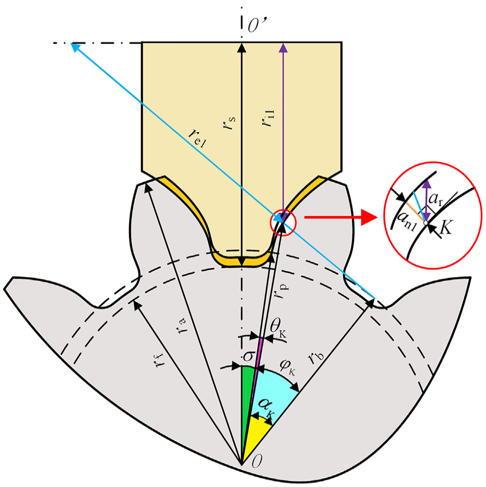
Grinding geometry model of the tooth profile involute segment.
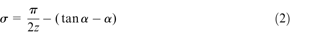
where ar is the radial grinding depth of the grinding wheel, φk is the rolling angle, φmax is the rolling angle at addendum circle and φmax =
If the transition arc radius of the tooth profile is rt, the centre of circle and arc angle are E and β, respectively. According to the form grinding geometry model of the transition arc segment (Figure 3), the normal grinding depth an2 at the arbitrary point K on the arc can be obtained as follows:
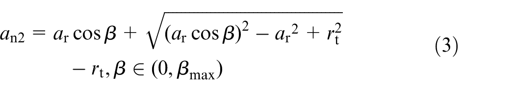
where βmax = π/2−σ.
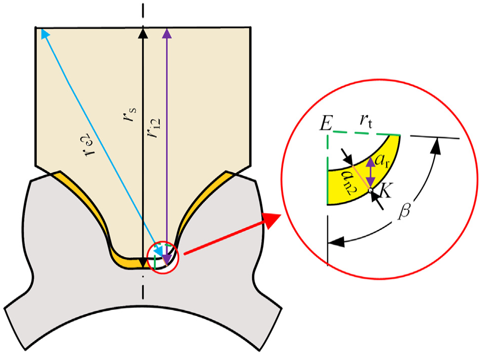
Grinding geometric model of the tooth profile transition arc segment.
At the tooth bottom where the CD segment is located, the profile line of the grinding wheel is parallel to the axis; thus, surface grinding can be considered the grinding method of this segment. At an arbitrary point on the tooth bottom line, the wheel normal grinding depth, an3, is equal to the wheel radial grinding depth. This depth can be denoted as follows:

According to equations (1) and (3), for different radial grinding depths, the variation trends of the normal grinding depth of the involute and transition arc segments with the rolling (Figure 4) and arc (Figure 5) angles, respectively, can be obtained. The basic structural parameters of the gear are as follows: the number of teeth z = 24, the modulus mn = 6, and the reference circle pressure angle α = 20°. It can be observed from Figures 4 and 5 that the normal grinding depth an in the involute and transition arc segments of the tooth profile increases with an increase in the rolling angle and decreases with an increase in the transition arc angle. The results reveal that the normal grinding depth is the largest and smallest at the tooth top and root, respectively.
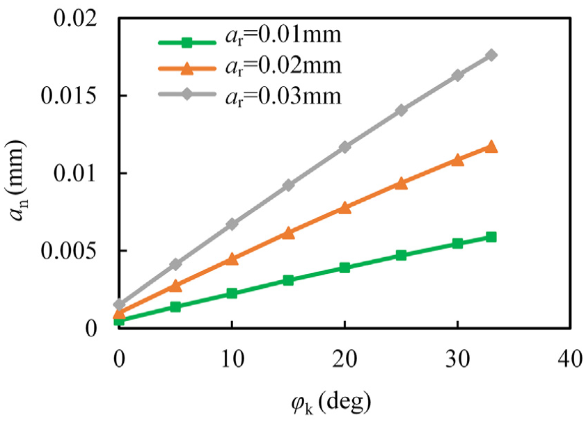
Relation between the normal grinding depth and rolling angle of the involute segment.
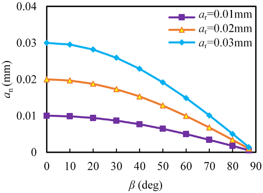
Relation between the normal grinding depth and arc angle of the transition arc segment.
Equivalent radius of the grinding wheel
The radius of curvature changes at each point of the gear involute tooth profile, and the grinding contact condition is different for each point between the grinding wheel and workpiece. Therefore, the equivalent radius of each point in the grinding contact zone of the wheel form surface is different. re1 and ri1 are the equivalent radius and radius of the involute segment of the grinding wheel form surface, respectively (Figure 2). rs and rp are the wheel initial radius before grinding and position vector of any point on the gear involute segment, respectively. OO’ represents the distance between the centres of the grinding wheel and gear,
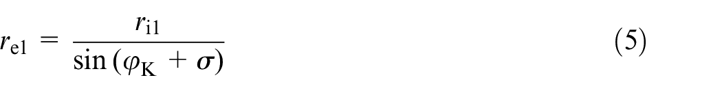
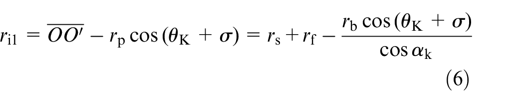
where θk is the unfold angle, αk is the pressure angle at any position on the tooth profile involute curve, θk = tanαk−αk, and αk = arctanφk. Equation (5) can be expressed as follows:
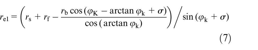
The equivalent radius at an arbitrary grinding contact point between the grinding wheel and transition arc segment of the tooth bottom can be determined as follows (Figure 3):
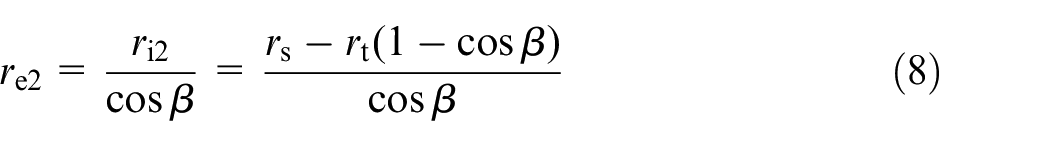
where ri2 is the radius at the arbitrary point on the transition arc segment of the grinding wheel form surface.
Additionally, at an arbitrary point of the tooth bottom line, the wheel equivalent radius re3 is equal to the wheel initial radius; re3 can be expressed as follows:

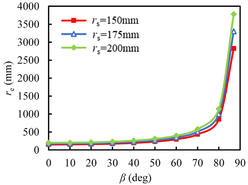
According to equations (7) and (8), the variations in the wheel equivalent radius for the same gear geometry parameters and different wheel initial radii are obtained. Figures 6 and 7 illustrate the relation between the wheel equivalent radius and rolling angle on the involute segment of the tooth profile and that between the wheel equivalent radius of the transition arc and arc angle, respectively. Taking into account the limitation of the grinding wheel installation size by the grinding machine and the actual situation of the workpiece size, three groups of values with the wheel initial radius of 150, 175, and 200 mm are selected. The wheel equivalent radius sharply changes at the arbitrary grinding contact point of the involute and the transition arc segments (Figures 6 and 7). At the position where the involute starts and at the tooth bottom line, the wheel equivalent radius is the largest and smallest, respectively. In addition, this radius shows a trend of sharp decrease with an increase in the involute rolling angle and decrease in the transition arc angle, respectively.
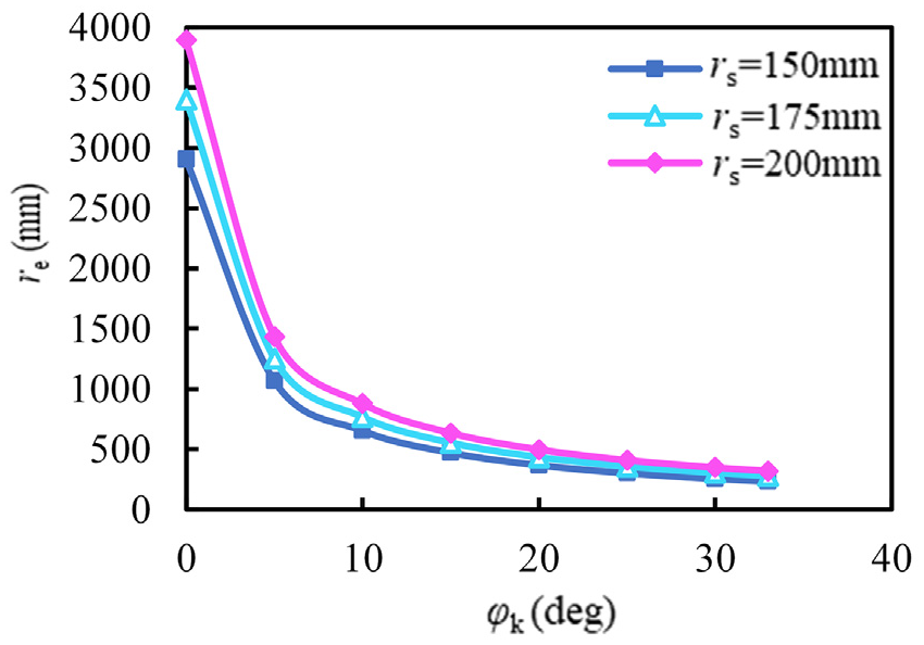
Relation between the equivalent radius of the wheel and rolling angle of the involute segment.
Relation between the equivalent radius of the wheel and arc angle of the transition arc segment.
Linear velocity of the grinding wheel
During gear form grinding, the actual wheel linear velocity can be obtained according to the radius observed at the arbitrary grinding contact point of the grinding wheel form surface and gear tooth profile. This velocity is expressed as follows:
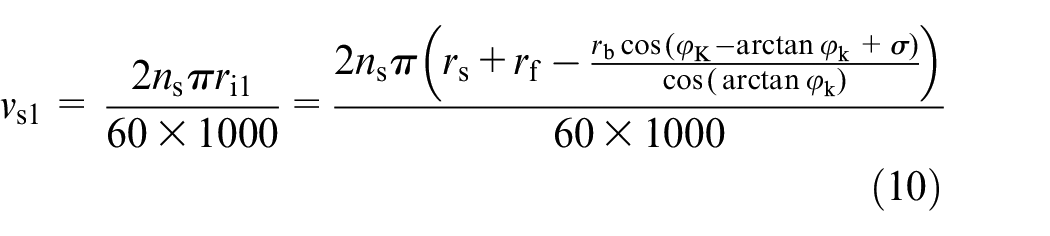
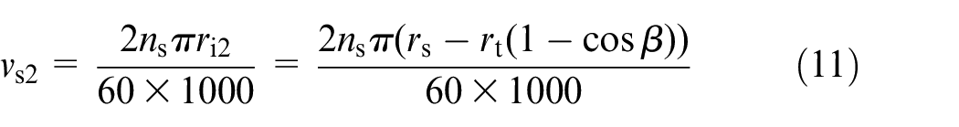
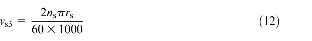
where vs1, vs2 and vs3 are the grinding wheel linear velocities of the involute, transition arc and tooth bottom line, respectively.
Assume that the grinding wheel speed is 1910 r/min. According to equations (10) and (11), the relation among the involute rolling angle, transition arc angle and wheel linear velocity under different wheel initial radii can be obtained. The wheel linear velocity decreases with an increase in the involute rolling angle of the gear tooth profile (Figure 8). This phenomenon indicates that the closer is the involute segment to the base circle, the higher is the grinding speed. The wheel linear velocity slightly decreases with an increase in the transition arc angle, indicating that the change in the transition arc angle exhibits little effect on the wheel linear speed (Figure 9). Thus, it can be considered that the wheel linear velocity of the transition arc segment is the same as the linear velocity of the tooth bottom line segment.
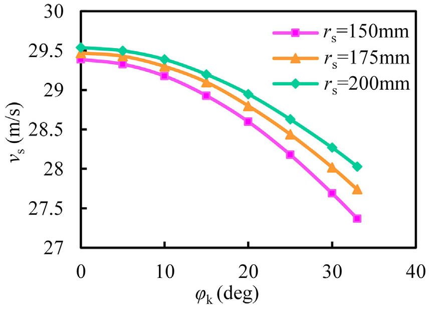
Relation between the wheel linear velocity and rolling angle of the involute segment.
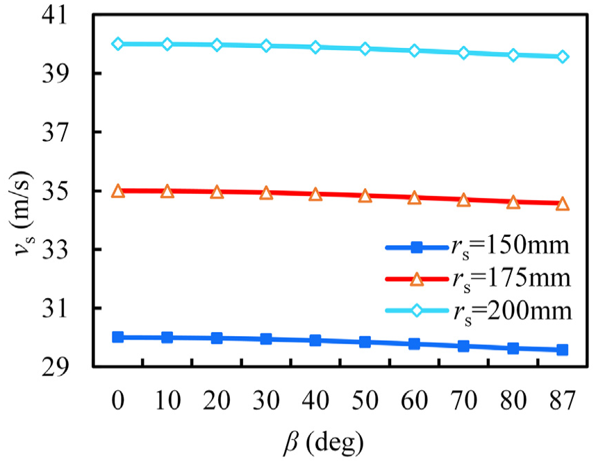
Relation between the wheel linear velocity and arc angle of the transition arc segment.
Grinding force calculation model for gear form grinding
In grinding, an amount of discretely distributed abrasive grains present on the grinding wheel surface is used to slide, plough and cut the workpiece. During grinding, after contact, the workpiece and each effective abrasive cutting edge of the grinding wheel undergo three stages: elastic deformation, plastic deformation and chip formation. The grinding force is derived from the resistance generated in the three stages and from the friction between abrasive grains, the bonding agent and the workpiece surface. The grinding force is commonly decomposed into three mutually perpendicular grinding components: the normal, tangential and axial grinding forces along the wheel radial, wheel tangential and wheel axial directions, respectively. The normal grinding force exhibits the largest value among the three grinding components, and is strongly related to the wheel compressive strength and rigidity of the grinding system. The axial force is small and can be omitted. By considering the influence of grinding parameters on the cutting deformation of metal materials, in surface grinding, Tang 11 proposed a unit width grinding force mathematical model, which is expressed as follows:
where
Any micro-segment present on the tooth profile involute segment can be analysed (Figure 10). The rolling angle of any point K on the involute is φk. When the rolling angle is increased of dφ, the involute arc length increment dl1 becomes:

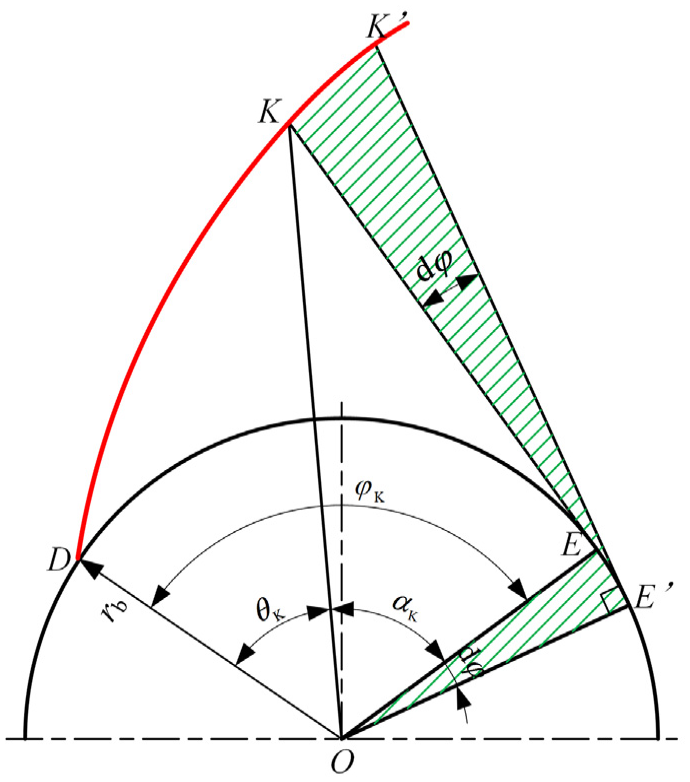
Micro-segmentation in the tooth profile involute segment.
Similarly, an arc length increase of the transition arc segment of the tooth profile is given as follows:

In the gear tooth bottom line segment, the length of the straight line can be expressed as follows:

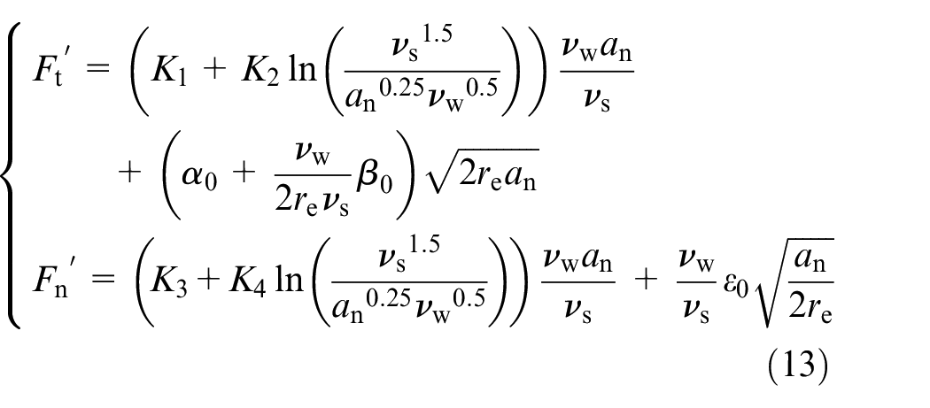
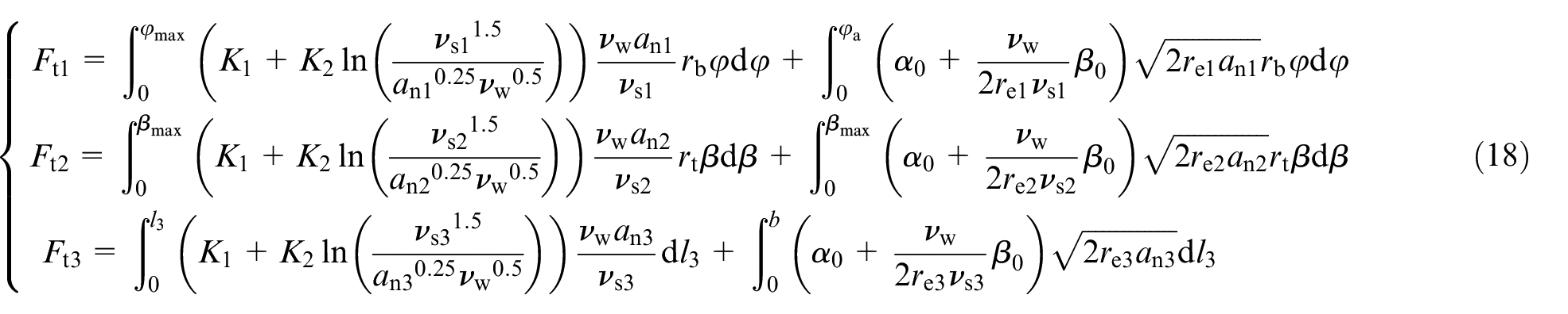
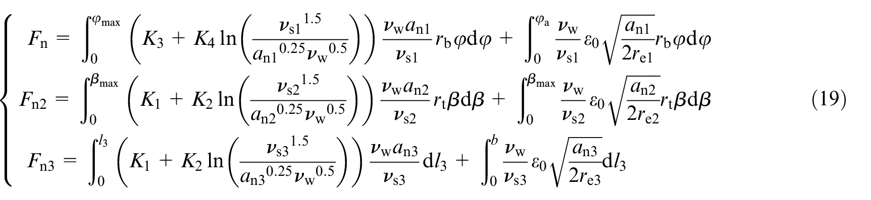
With the unit width grinding force calculation model of surface grinding, the unit width grinding force is applied along the direction of actual grinding contact arc length to obtain the gear form grinding force:
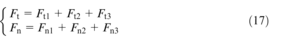
where Ft1, Ft2 and Ft3 are the tangential grinding forces along the involute, transition arc and tooth bottom line, respectively. Fn1, Fn2 and Fn3 are the normal grinding forces along the involute, transition arc and tooth bottom line, respectively. The calculation formulas used are equations (18) and (19).
where b represents the half tooth groove width of the dedendum circle, b = rb sinβ−rt cosβ.
Experiment setups
Gear grinding machine and measurements
Grinding experiments were conducted on the BLOHM PROFIMAT MT-408 high-speed surface precision grinding machine. The maximum spindle power of the machine tool is 62 kW, the limit speed is 6000 r/min, and the range of worktable feed speed is 15 mm/min–25 m/min. In the grinding force measurement, a dynamometer (KISTLER-9257) is applied. The generated charge signal is initially converted into a voltage signal by using a selectable X–Y–Z charge amplifier. Then, the analogue voltage signal is converted into a digital voltage signal through a data acquisition card, and eventually, the digital voltage signal is collected and processed using the dynamic test and signal analysis system. Figure 11 illustrates the gear form grinding system.
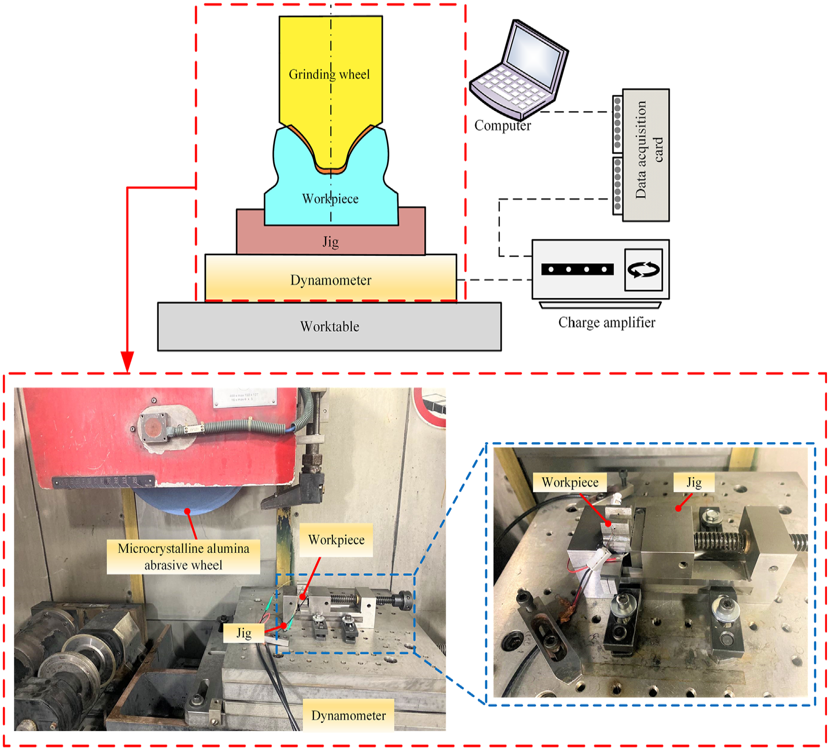
Gear grinding experiment system.
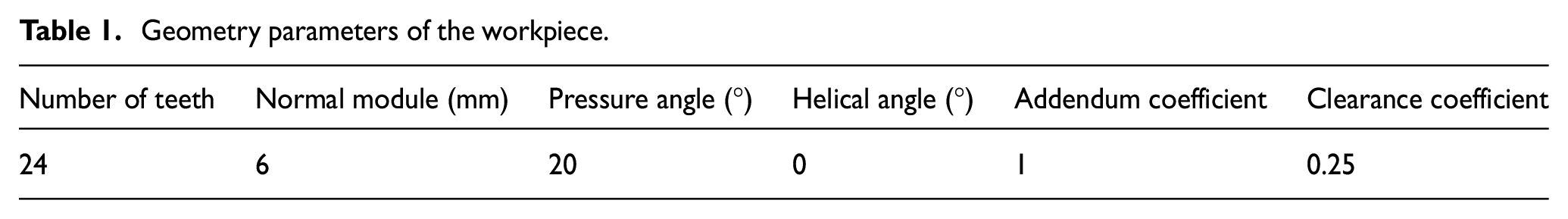
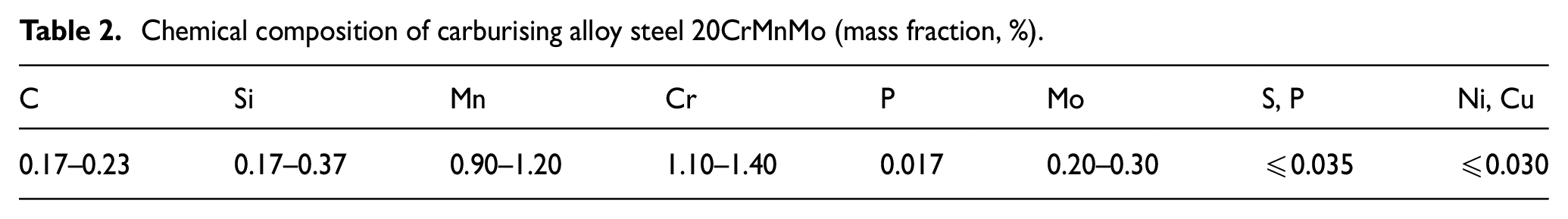
The microcrystal alumina abrasive wheel presents the advantages of high toughness, satisfactory self-sharpening and strong imitation ability. Therefore, a form grinding wheel (Φ350 × 25 × 127 mm, 4CA70GH50) which had the vitrified bond, average cutting diamond diameter of 178 µm and ceramic microcrystalline alumina abrasive (CA) was used for the grinding test. The workpiece was a single tooth cut from a complete involute spur gear. The geometry parameters of the involute spur gear are listed in Table 1. The workpiece material is carburised steel 20CrMnMo. Table 2 presents the chemical composition. To satisfy the neutrality requirements in the grinding tooth profile, the gear is precisely measured using the three-coordinate measuring instrument before gear cutting. The median line of the two tooth surfaces must be cut perpendicular to the wheel axis with accurate calculations. Table 3 presents the basic material parameters of the workpiece and grinding wheel abrasive grain.
Geometry parameters of the workpiece.
Chemical composition of carburising alloy steel 20CrMnMo (mass fraction, %).
Basic material parameters of the grinding wheel abrasive grain and workpiece (20°C).
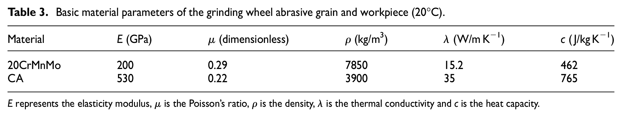
E represents the elasticity modulus, µ is the Poisson’s ratio, ρ is the density, λ is the thermal conductivity and c is the heat capacity.
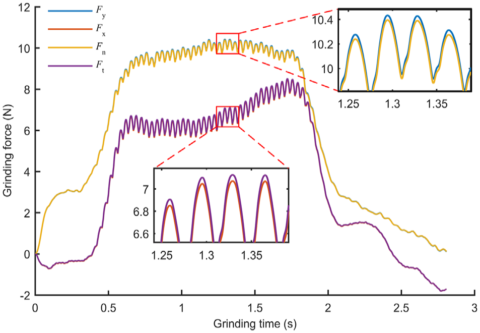
Figure 12 shows a group of grinding forces obtained in the gear form grinding experiment. The grinding parameters are as follows: vs = 32.5 m/s, ar = 0.01 mm and vw = 1000 mm/min. Fx and Fy are the tangential and normal grinding forces, respectively, which are parallel and perpendicular, respectively, to the worktable feed direction. Additionally, during the overall grinding process, the variation tendency of the grinding force observed in the experiment (Figure 12) exhibits an initial increase, followed by stabilisation, and final decrease.
Grinding force measured in the experiment.
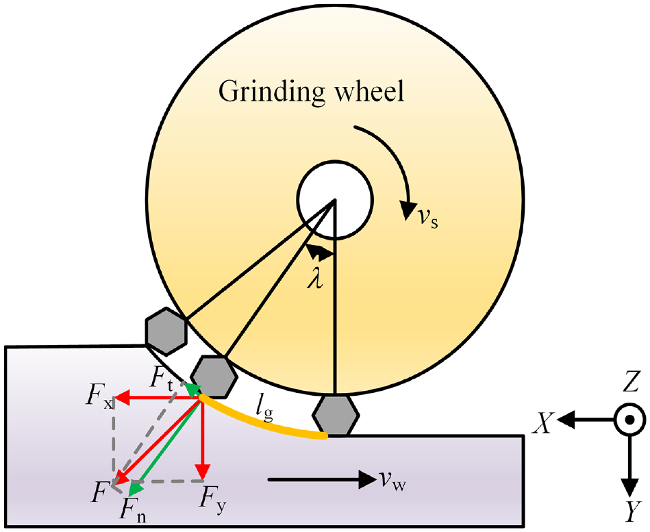
The grinding forces Fx and Fy measured in the global coordinate system of the machine tool must be converted into normal (Fn) and tangential (Ft) grinding forces in the workpiece coordinate system (Figure 13). The transformation relationship is as follows:
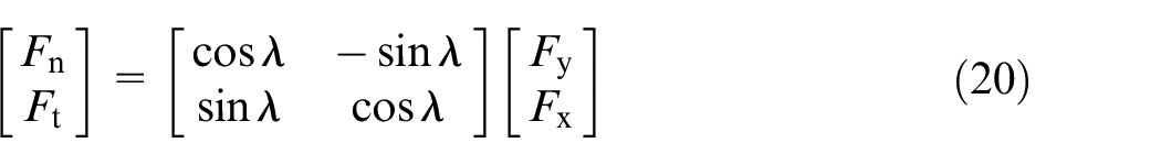
where λ is the rotation angle of the grinding wheel, lg is the geometric contact arc length of the grinding contact zone. The relationship between λ and lg is
Measured grinding force conversion.
Figure 12 presents the normal (Fn) and tangential (Ft) grinding forces acquired after coordinate transformation. The zoom-in view shows that after conversion, the values of Fn and Ft exhibit a small decrease and increase, respectively.
Grinding experiment design
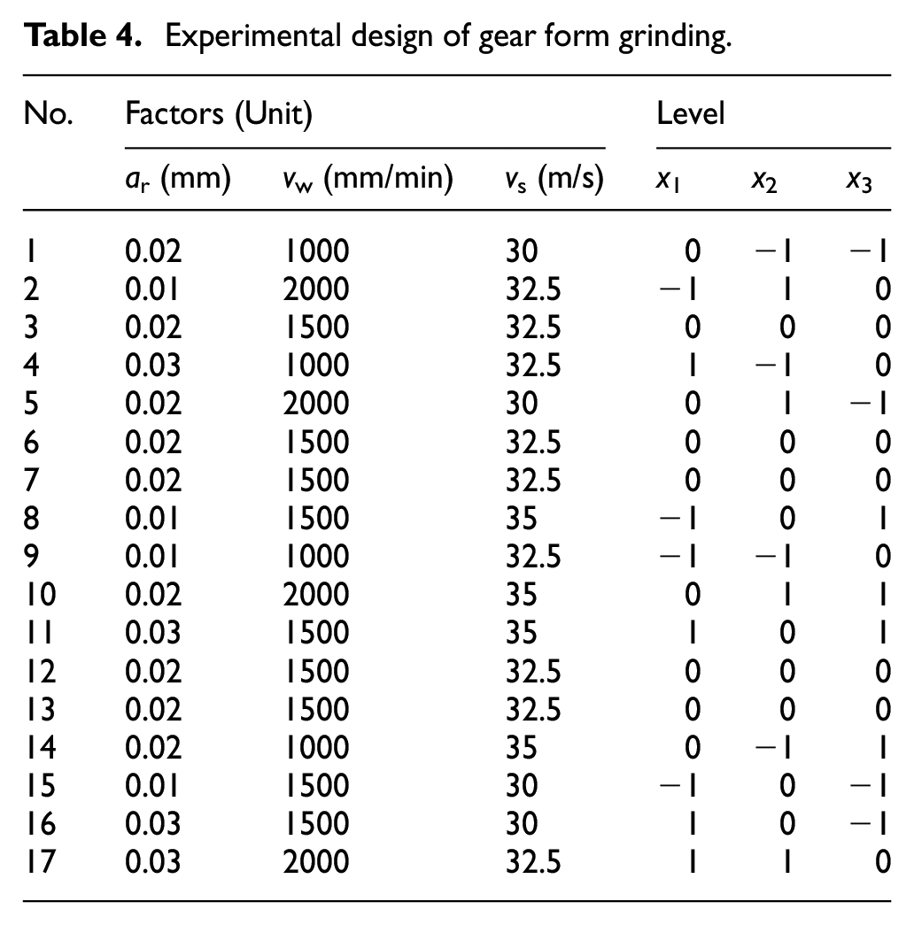
Based on the actual requirements of gear grinding, the Box–Behnken design method is used in experiments. Grinding depth ar, workpiece feed speed vw and wheel linear speed vs are selected as the influencing factors. The level of each influencing factor is coded as (−1, 0, 1), where ‘0’, ‘1’ and ‘−1’ represent the central point, high level and low level, respectively. According to the principle of the Box–Behnken central combination design, polynomial models with interaction terms can be estimated with a few experiments. Table 4 presents the specific experimental design.
Experimental design of gear form grinding.
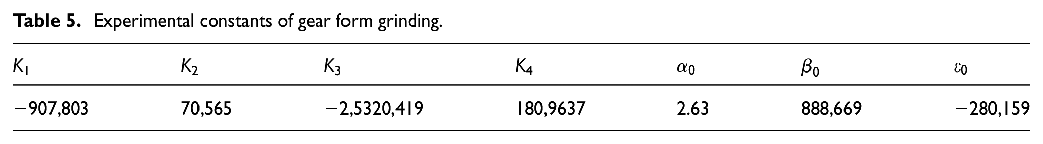
By substituting the first four groups of the experimental results into equations (18), (19) and (20), the values of unknown parameters K1, K2, K3, K4, α0, β0 and ε0 can be obtained. Table 5 presents the results.
Experimental constants of gear form grinding.
Grinding experiment results discussion
For involute gear form grinding, the relation between grinding parameters and the grinding force can be obtained using the grinding force calculation model (Figure 14). Under the same grinding parameters, the normal grinding force Fn is larger than the tangential grinding force Ft because the abrasive grain exhibits a relatively larger negative rake angle, and the squeezing effect of the abrasive grain is stronger than its friction effect during grinding. In the case of changing grinding parameters, Fn and Ft exhibit the same variation trend: if one parameter remains constant, then under the interaction of the other two parameters, the grinding force almost linearly increases or decreases. The grinding force increases with an increase in the workpiece feed speed vw and grinding depth ar and decreases with an increase in the wheel linear speed vs because the increase in vw leads to an increase in the cutting thickness and material removal rate of the single-abrasive grain, thereby resulting in a grinding force increase. When ar increases, both the number of effective abrasive grains involved in grinding and amount of the material removed per unit time increase. Therefore, the resistance required to generate chips and the friction between the abrasive grain and workpiece surface increase, which leads to an increase in the grinding force. When vs increases, the number of abrasive grains in the grinding zone per unit time increases, and the maximum undeformed cutting thickness of the single abrasive grain decreases. Consequently, the effective grinding force of the single abrasive grain is minimised. Additionally, the increase in vs causes an increase in workpiece surface temperature, and the thermal softening effect resulting from temperature increase leads to an increase in the workpiece plastic flow; thus, the grinding force required for material remove is minimised.
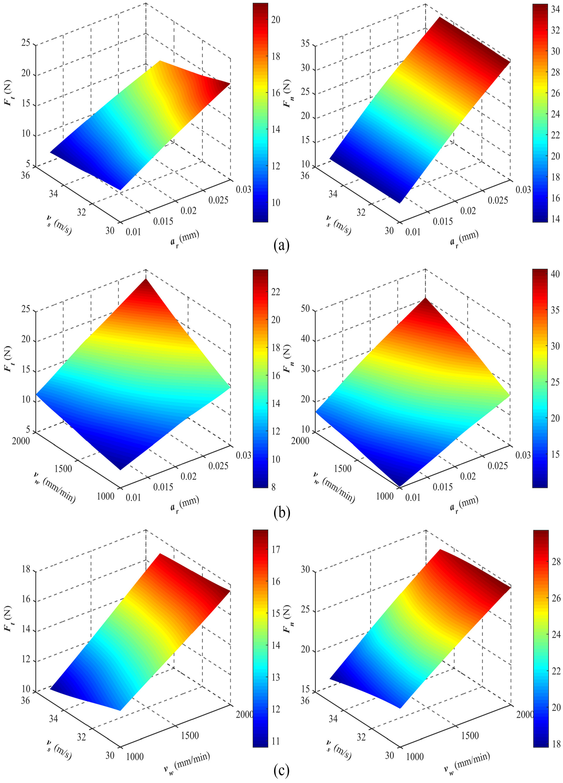
Relation between grinding parameters and the grinding force: (a) relation between the grinding speed, grinding depth and the grinding force (vw = 1500 mm/min), (b) relation between the feed speed, grinding depth and the grinding force (vs = 32.5 m/s) and (c) relation between the grinding speed, feed speed and the grinding force (ar = 0.02 mm).
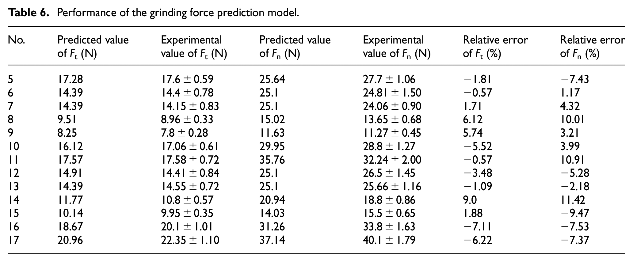
For gear form grinding, the predicted results of the grinding force model are compared with the experimental results. The test for each group was repeated three times. Table 5 presents the measured grinding force results including standard deviations. The comparison results between prediction and experiment (Table 6) showed that the relative errors of the tangential and normal grinding forces are within ±10% and ±12%, respectively. The experimental results are in strong agreement with the prediction results of the grinding force calculation model.
Performance of the grinding force prediction model.
Conclusions
Under the condition of complete tooth depth engagement in tooth grooves and grinding wheel profiles, the grinding force of gear form grinding is analysed and verified using the analytical model and experiments. The contributions and conclusions of this study are as follows:
For gear form grinding, the analytical model of the grinding force is established based on the geometric model of the complete tooth depth form grinding and the unit width grinding force model of surface grinding. Furthermore, the unknown coefficients of the analytical model are obtained through single-tooth experiments.
The three segments of the involute, transition arc and tooth bottom line included in the complete tooth groove profile were analysed in detail, and the geometry model of gear form grinding was established. Based on the geometric model, the contact relation among normal grinding depth, wheel equivalent radius, wheel linear velocity and wheel profile was analysed. The results revealed that the grinding depth is the largest and smallest at the tooth top and root, respectively. The equivalent radius is the largest and smallest at the involute starting position and tooth bottom line, respectively. The wheel linear velocity is the highest at the starting position of the involute, and that on the transitional arc and on tooth bottom line is the same.
Using the analytical grinding force model of gear form grinding, the interactive influence of grinding parameters on grinding force can be analysed. The grinding force increases with an increase in workpiece feed speed vw and grinding depth ar and decreases with the increase in the grinding wheel linear speed vs.
According to the comparison of the prediction value of the calculation model with the experimental value, that the relative errors of tangential and normal grinding forces are within ±10% and ±12%, respectively. The accuracy of the grinding force calculation model is verified. The finding is fundamental for gear form grinding optimisation and grinding surface quality enhancement.
Different from existing studies on gear form grinding, which have only focussed on the grinding force of involute segment, this gear form grinding force model emphasised in detail on three segments of complete tooth groove profiles: involute, transition arc and tooth bottom line. However, conduct experiments to accurately and separately measure the grinding force of the three segments is difficult. The grinding force can only be measured when in the complete engagement case; thus, the changes in the grinding force cannot be analysed at the cogging joint. Future studies can explore gear form grinding experiments to separately measure the grinding force.
Footnotes
Declaration of conflicting interests
The author(s) declared no potential conflicts of interest with respect to the research, authorship, and/or publication of this article.
Funding
The authors disclosed receipt of the following financial support for the research, authorship, and publication of the article: All the authors of this article gratefully acknowledge the help and support of National Key Research and Development Program of China (2018YFB2001503) and the Defense Industrial Technology Development Program (JCKY2020213B006).