
Abstract
In this study, laser shock peening (LSP) has been applied on austempered ductile iron (ADI) to determine the optimum laser power and spot overlapping rate required for automotive gear applications. The surface roughness and phases present were studied to understand the effect of the laser shock wave application on the material. An increase in the mean surface roughness was achieved when the laser spot overlap increased from 20% to 60%. A significant increase in the microhardness was obtained in the surface and sub-surface, indicating an increased dislocation density of the material. Compressive residual stress depth and magnitude characterized by X-ray Diffraction (XRD) and Incremental Hole Drilling (IHD) were found to increase with laser power density. This work significantly identifies the pathway toward the engineering manufacture of austempered ductile iron and the application of LSP for the automotive drive-train industries.
Introduction
Ductile Iron (DI) is part of the family of cast irons and is composed of a ferrous matrix, together with spherical graphite nodules, which are very effective at inhibiting crack propagation. As a result, it increases the material’s toughness and machinability. 1 DI exhibits a combination of various desirable properties such as good compressive strength, moderate hardness, good machinability, high fluidity and excellent thermal conductivity. 2 These properties can be further improved via an austempering heat treatment, to produce Austempered Ductile Iron (ADI), consisting of graphite nodules in a matrix of ferrite and retained austenite. 1 However, failure can still result at the surface and sub-surface of the component, hence the need to improve the structural integrity of the ADI by modifying the surface conditions such as grain refinement at the micro level. 3
Effective surface improvement can be achieved with the application of different surface engineering treatments, such as mechanical shot peening, ultrasonic peening, Low Plasticity Burnishing (LPB), Surface Mechanical Attrition Treatment (SMAT), and Laser Shock Peening (LSP). These treatments will negate the tendency for crack initiation or propagation during operation under cyclic loading by inducing compressive stresses on the surface and near-surface regions.3–5 In contrast to other mechanical surface treatments, LSP is a non-contact method and has the advantage of improving the lifespan of the metal without any peening-induced defects.5,6
On the other hand, other shot peening processes have the disadvantage of causing a significantly rough surface, comprising surface defects which can lead to crack formation. It can be expected that a high surface roughness would accelerate crack nucleation, even though it may have a minimal effect on its propagation.
Specifically, LSP has been determined to cause an almost six-fold improvement in the nanohardness of commercially pure titanium due to the occurrence of grain refinement phenomenon in the near-surface region by micro twins and dislocation cells generated by the LSP process.4,7 Such a high degree of cold work is expected to retard crack nucleation and accelerate crack propagation. On the other hand, compressive residual stresses would have minimal effect on crack nucleation, while retarding crack propagation.
It has been suggested that LSP can be readily implemented in all metals requiring an improvement in their mechanical properties, especially the fatigue life. 7 However, LSP should be performed using proper process parameter optimization. The key properties relevant to this research are surface roughness and surface/near-surface microstructure in order to optimize the respective LSP parameters. An extensive survey of the literature points out the ambiguous nature of the reported surface properties resulting from laser peening. Specifically, the formation of an amorphous layer at the surface, a nanocrystalline layer near the surface and the surface roughness correlation to fatigue life remain subjects of contention, where the laser parameters need to optimized to any particular material.
Laser shock peening is one of the most novel methods used in surface modifications in components used in the automotive and aerospace industries. Nd:YAG lasers with the fundamental frequency and the second harmonic generated frequency are both usually deployed in the LSP process.4,6 As soon as the induced shock pressure increases higher than the dynamic yield strength of the treated material, plastic deformation and compressive stress occur at the surface and subsurface of the workpiece. 3 The volume influenced by the shock wave is plastically strained amid its spread to an intensity at which the peak pressure no longer surpasses the metal’s Hugoniot Elastic Limit (HEL). The neighboring material in the sub-surface resists straining in a plane parallel to the surface where biaxial compressive residual stresses are formed.
The LSP process creates smoother surfaces than that produced by the shot peening process. In addition, the induced compressive layer depth is higher than its shot peened counterpart. 8 Another similar process is Surface Mechanical Attrition Treatment (SMAT), during which the deformation mode is multi-directional which facilitates in activating multiple slip systems and increases dislocation interaction frequencies which leads to the formation of sub-grains via grain refinement with shorter processing time. 9 However, the magnitude of the compressive stresses is larger when processing using LSP.
The objective of the current work is to investigate the effect of various laser shock peening parameters on the residual compressive stresses, microstructure, surface topography and hardness on austempered ductile iron (ADI) alloyed with copper and nickel. Several studies show how LSP interacts with various materials such as stainless steel, titanium alloys, advanced ceramics and aluminum alloys. 3 Other studies have shown that SP is useful to increase the bending fatigue resistance of the ADI, 10 but SP is not always suitable to improve the tribological characteristics.11,12 These results were attributed to the beneficial residual compressive stresses and increased surface hardness, but which were then counterbalanced by the induced surface roughness. Therefore, this work has been carried out in an attempt to provide deep residual compressive stresses similar to SP, without distorting the surface. Also, studies on the effect of LSP on ADI are very novel in this field, so it is interesting to see the effect of the LSP on the ADI and compare it with the SP process.
Key fundamental investigations into the mechanisms of LSP consistently show that the peak plasma pressure generated is a function of laser power density. The analytical model of Berthe et al. 13 gives the following law of the maximum plasma pressure Pmax (GPa):
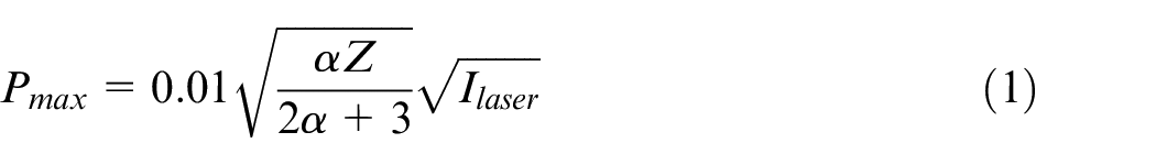
where Ilaser is the laser power density in GW/cm2, Z is the harmonic mean of the shock impedances (in g/cm2/s) of the considered metal and confinement, and α is the fraction of the total plasma internal energy used as thermal energy. The peak pressure increases with the square root of the laser power density up until a threshold referred to as the saturation limit is reached. Historically, the saturation threshold is 5–6 GW/cm2 at a 532 nm wavelength and around 10 GW/cm2 at 1064 nm. However, the early works on peak pressure measurements considered lasers with pulse durations in the range of 25–30 ns. More recent works using a 532 nm wavelength with a shorter pulse duration of 7 ns reveal increasing shock pressures up to 20 GW/cm2, 14 and a 6 ns pulse duration pressure saturation at 24 GW/cm2. 15 Increased peak pressures were found to occur for submerged water confinement compared to a thin water layer.
Therefore, apart from showing that the LSP process successfully provides a surface strengthening technique suitable for automotive ADI materials, this work further explores the parameter development in the emerging parameter space of LSP processing using 532 nm laser systems with shorter pulse duration (around 6 ns compared to 25 ns). The laser power density (GW/cm2) is a key process parameter to be developed for the current application.
Methodology
Material
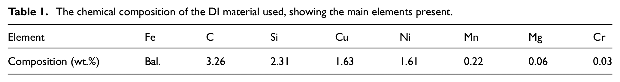
As-cast ductile iron, having the chemical composition shown in Table 1, containing more than 95% nodularity, an average nodule size of 27 μm and a nodule count of 200 nodules per mm2, was used for this study. Samples having dimensions of 20 mm × 20 mm × 15 mm were first austenitized at a temperature of 900°C ± 5°C for 2 h, then austempered in sodium nitrate salts for 90 min at a temperature of 360°C ± 2°C, followed by cooling in air to room temperature. Any etching was carried out using 3% Nital.
The chemical composition of the DI material used, showing the main elements present.
Laser shock peening
Laser shock peening was performed at the Council for Scientific and Industrial Research (CSIR) in South Africa on ground and polished ADI samples having a surface roughness Ra of 0.17 ± 3 μm. A pulsed Nd:YAG laser (Thales SAGA) operating at a wavelength of 532 nm was used, having a fixed pulse duration of 5.1 ns was delivered in a spot diameter of 1 mm. Inertial confinement was provided by a thin layer (of approximately 1 mm thickness) of water achieved with a spray nozzle. The material was covered by black vinyl tape (with a thickness of 100 microns) as the sacrificial layer to preserve the surface integrity and to ensure a pure mechanical cold working process. 16 The parameters explored in this study are laser power density and spot overlap. As a preliminary screening technique, an Almen strip approach adapted for LSP process parameter evaluation was employed to estimate the saturation threshold for laser power density. 17 The Almen deflections for the laser used in this study (532 nm wavelength with a 5.1 ns pulse duration) are compared for a laser operating at 1064 nm with an 8.6 ns pulse duration (Figure 1). The Almen data clearly reveals significant deflection beyond 15 GW/cm2 for the current laser. Historically, 532 nm LSP processing applied for stainless steel uses a power intensity range of 5–6 GW/cm2. 18 The laser power density for this study was therefore varied between 5 and 25 GW/cm2 to explore the emerging parameter space for the 532 nm laser source with a 5.1 ns pulse duration.
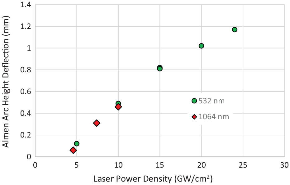
A comparison of Almen arc height deflections for increasing laser power density for 532 and 1064 nm LSP conditions with a spot diameter of 1 mm and overlap of 50%.
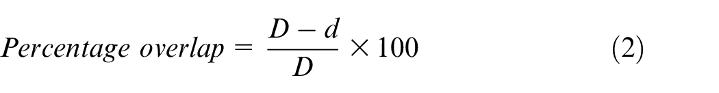
The spot overlap was achieved using a conventional XY raster pattern, where the scanning and step direction are shown in Figure 2. The laser pulses at a fixed repetition rate of 10 Hz, therefore controlling the scan velocity will set the spot separation distance (d) between successive laser pulses. The step dimension is set equal to the spot separation distance (d) which creates equal overlap in the X and Y directions. The overlap of each spot can be expressed as a percentage (%), and is illustrated in Figure 3. For a spot diameter (D), the percentage overlap is therefore defined as:
Since the tape is used as a protective coating, consideration of the structural integrity of the coating is important for a robust process, which is expected to be limited by the overlapping rate, as at some threshold, the tape will be damaged, and no longer perform as an effective protective coating. The pulse overlap varied between 20% and 60% to evaluate the tape adherence threshold, as shown in Figure 3. The size of the LSP area was 15 mm × 15 mm applied to the 20 mm × 20 mm sample face.
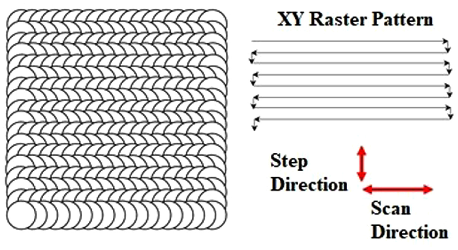
Laser spot scanning direction used for laser shock peening.
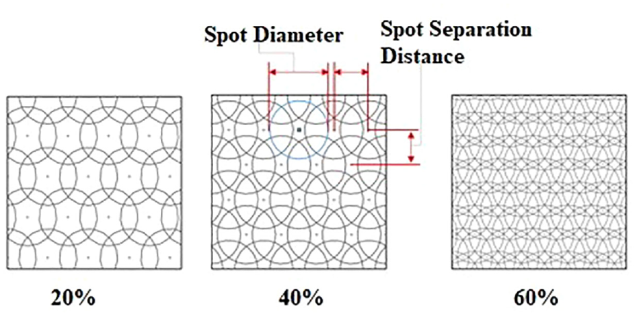
Schematic diagrams for different laser spot overlapping percentages during the laser shock peening process.
Material characterization
Specimens were analyzed using a Nikon light optical microscope which was equipped with a Leica DFC290 digital camera and a Leica IM500 Image Manager Software. Before microscopic analysis, the sacrificial black vinyl tape was removed from the peened specimens, and the samples were cleaned from any adhesive in Isopropyl alcohol. Cross-sections of the peened specimens were cut using a Struers Accutom-10 precision cutter, the cut-off sample was then mounted in phenolic resin by a Remet IPA 30 hydraulic press, followed by grinding, polishing, and etching.
Microhardness tests were performed via a Mitutoyo MVK-H2 microhardness testing machine loaded with a 300-g force, having a dwell time of 10 s. The final results of the hardness-depth profiles have been produced after taking an average of 10 measurements at each depth step on the cross-sectioned material.
2D and 3D scans of surfaces were obtained with an AEP Technology NanoMap 500 LS 3D profilometer equipped with a stylus of 1 μm radius exerting a 25 mg force on the samples. The SPIP 6.3.3 software was used to analyse the topographic scans produced. The roughness along the 1000 scans performed was obtained and the mean surface roughness was calculated.
A Bruker D8 Advanced Diffractometer equipped with a copper source (Cu Kα radiation) was used to carry out phase analysis using X-ray Diffractometry. The XRD patterns were obtained at a scanning step of 0.02° with 2θ values ranging from 20° to 120°. The voltage, current and scanning speed used were those of 45 kV, 40 mA and 1°/min, respectively. Due to the limited penetration depth of X-rays, the XRD technique only provides residual stress information for the very near-surface (depth of a few microns only). The Incremental Hole Drilling (IHD) technique for residual stress measurements, can provide information on the millimeter range, however with poor reliability on the surface. XRD and IHD are therefore highly complementary techniques, where a combination is highly suited for evaluation of LSP induced residual stress. 19 The IHD process was executed on a SINT MTS3000-Restran instrument, equipped with EVAL 7 Premium Software. Drilling was performed using a high-speed inverted cone carbide end-mill to drill a 1.2 mm hole in 60 increments of 0.02 mm. Type A strain gauges (CEA-13-062UL-120) have been used with a nominal hole diameter of 2 mm, which allows for reporting of residual stresses to a depth of 1 mm. The stresses have been calculated as per the ASTM E837-13 EXT formulation for non-uniform residual stresses. 21 Interpolated strains to a fitted polynomial were performed, and stress results are reported at 20 equal steps with the application of a Tikhonov correction applied. A Young’s modulus of 158 GPa and Poisson’s ratio of 0.25 has been used as constants for the calculation of residual stresses for both XRD (converted to X-ray Elastic Constants) and IHD measurements.
Results and discussion
Residual stress measurement analysis via XRD and incremental hole drilling technique for different laser power densities
The XRD sin
2
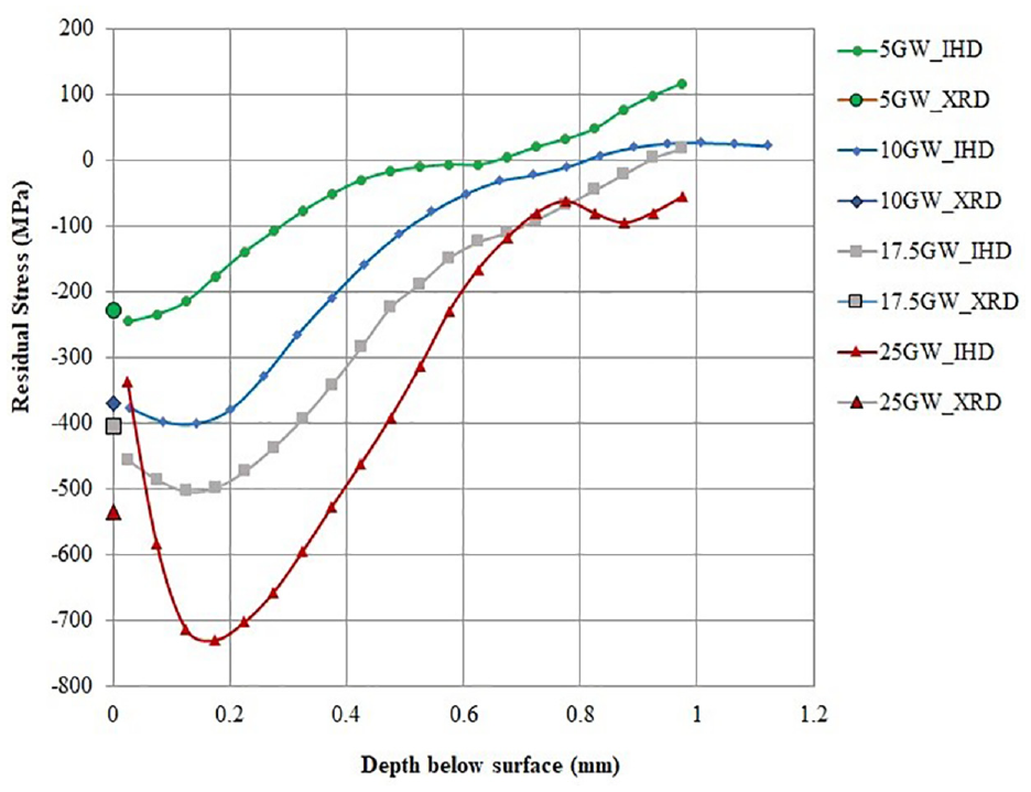
Residual stress-depth profile for the laser shock peened ADI specimen at different power densities measured using the hole-drilling method (Laser power density units are in GW/cm2).
The indicated peak compressive stress of 720 MPa is lower than the 975 MPa compressive value reported by Zammit et al., 10 who carried out conventional mechanical shot peening on identical ADI material. This reduced stress generation can be attributed to the fact that in the previous study the material underwent a phase transformation from austenite to martensite at the affected surface, which resulted in a 4% increase in volume, causing an amplification of the compressive stresses but also leading to the creation of further sub-microscopic stresses and dislocations.
The LSP data presented show that this maximum stress gradually decreases with distance and extends up to a depth of about 1 mm. Necessarily, this is the result of the laser shock wave which is maximum on the surface and decreases as the shock wave is attenuated during its passage into the depth of the sample. Moreover, compressive residual stresses are induced with low work hardening, acting to impede thermal stress relaxation. Herein, the highest laser power density, that is, 25 GW/cm2, indicates a larger value of compressive residual stress induction.18,19
The study reveals that the higher laser power density used for the laser shock peening process has the effect of inducing larger and deeper compressive residual stresses for the laser spot diameter of 1 mm, as shown in Figure 4. The higher overlapping rate at very high-power densities may cause a deterioration of the surface finish, even though the sub-surface compressive residual stresses are effective. Clearly, the laser shock peening process, with the use of PVC ablative tape, can operate at high power densities with a lower overlapping rate, thus avoiding thermal heat effects. 21
X-ray Diffraction residual stress measurement analysis
The surface residual stress field was studied using X-ray diffractometry and specifically the sin2Ψ technique for the different overlapping rates between 20% and 60%. Figure 5 shows that there is a negligible amount of residual stresses on the as-received ADI specimen’s surface. The PVC tape failed after laser shock peening beyond the 40% overlapping rate, indicating that higher overlapping may result in surface deterioration as well as an unstable process. Furthermore, the higher overlapping induced sufficient heat which affects the amphiphilic nature of the surface, thus altering the surface conditions. Hence, to avoid this, the current studies restrict the overlapping rate to only 20% to investigate the optimized laser power density to induce higher compressive residual stress (Figure 5). 6
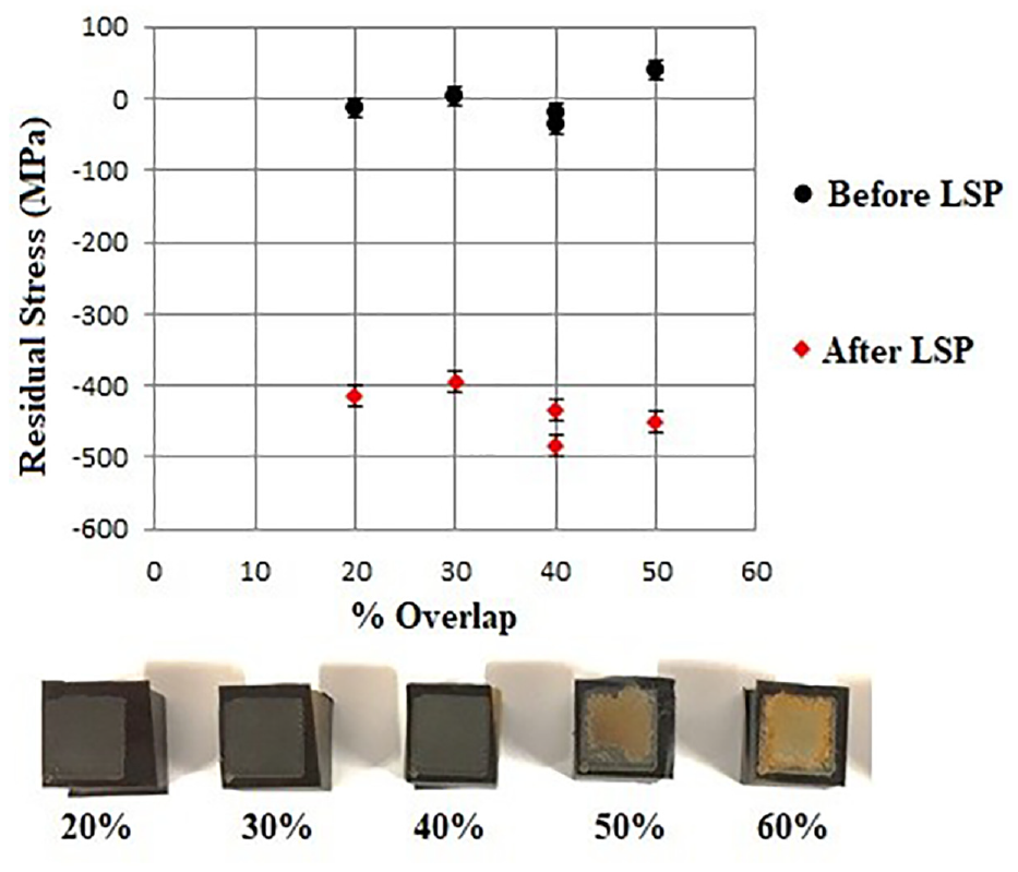
The near-surface residual stress for different laser spot overlapping rates (at 12.5 GW/cm2) measured by X-ray diffraction.
Figure 6 shows the near-surface residual stresses induced through LSP at different power densities. A laser power density of 5 GW/cm2 is insufficient to induce high compressive residual stresses. On the other hand, the near-surface compressive residual stresses do increase as the laser power density increases, especially in the range of 5 to 12.5 GW/cm2. In this case, experiments were carried out up to a maximum power intensity of 25 GW/cm2, to prevent deterioration of the surface due to excessive heat produced during the laser-matter interaction. 21 The trend shown is that with increasing power intensity the magnitude of the compressive stress reaches saturation at around 12.5 GW/cm2. It is also noted that increasing the overlapping rate has no significant effect on the magnitude of surface residual stress for this alloy, as observed in Figure 5. Therefore, the current results suggest that laser power density is an important parameter to optimize for this application.
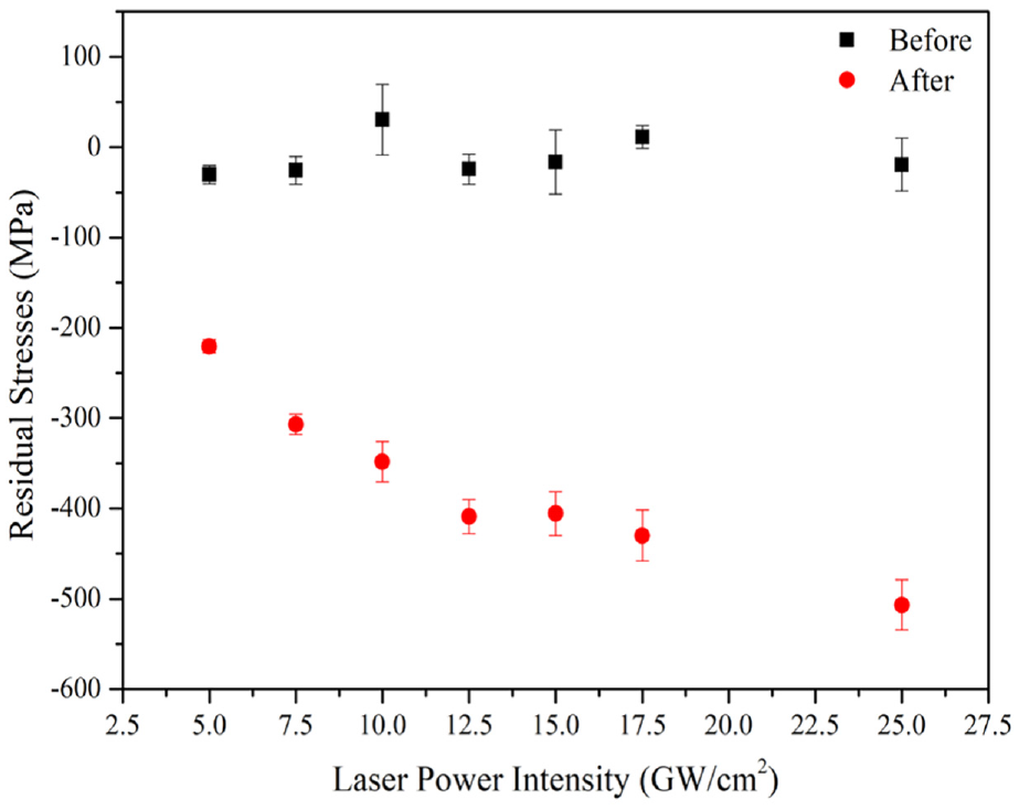
Near-surface residual stress profile for the laser shock peened ADI specimen at different power densities.
Microstructure analysis
The microstructure of the as-cast ductile iron is made of graphite nodules surrounded by bull’s eye ferrite, which are evenly dispersed in a pearlitic matrix, as shown in Figure 7(a). The ADI microstructure, consists of graphite nodules dispersed within an ausferrite. Figure 7(b) shows that the acicular ferrite content was higher in regions near the graphite nodules than in those areas which were not in close proximity of the nodules. Following the LSP process, the specimens treated with a power intensity of 12.5 GW/cm2, a spot size of 1 mm in diameter and an overlapping rate of 20% were analyzed. Graphite nodules with acicular coarse ferrite embedded in a blocky austenitic matrix were identified, as shown in Figure 7(c) and (d). This indicates that the austenite has been transformed from needles of ferrite to a blockier form following LSP, the latter typically forming in prior austenite grain boundaries. This provides a reduction in stability of the retained austenite when compared to that of a film-like morphology. 22 Austenite is comprised of multiple slip systems which develop during this deformation and create work hardening.
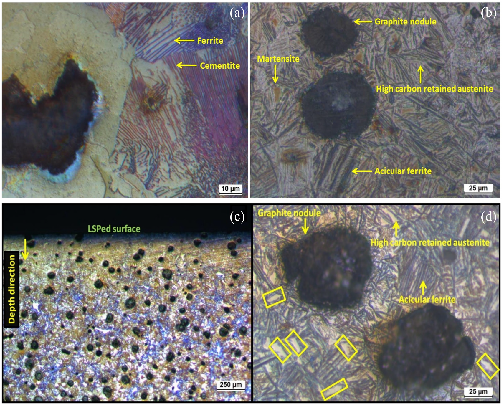
Microstructure of (a) ductile iron, (b) austempered ductile iron, (c and d) laser shock peened austempered ductile iron at 20% overlapping rate (etched with 3% Nital Solution). The areas marked with a yellow rectangle in Figure 6 (d) depict blocky areas of austenite.
Surface topography
The laser spot overlapping rate during the LSP process plays a significant role in imparting the emerging shock waves during laser ablation. Since the experiment used PVC tape as an ablative medium, the study looked at optimizing the overlapping rate of the laser spot with a fixed laser spot size. The laser pulse overlap was first varied between 20% and 60%, keeping the laser power density fixed at 12.5 GW/cm2, as shown in Figure 8. Figure 9 shows the surface roughness values for the samples having a laser spot overlap ranging from 20% to 60% and the same intensity of 12.5 GW/cm2. The mean surface roughness Ra values range from 0.8 to around 1.4 μm, with graphite nodules also contributing to the increased surface roughness. As the laser spot overlap was increased, more fluctuations were present in each scan. The fluctuations can be attributed to the following reasons: (i) deformations in the surface following LSP, (ii) to any remaining roughened surface generated during the LSP or (iii) to the failure of the ablative layer, leaving the samples without any protection.
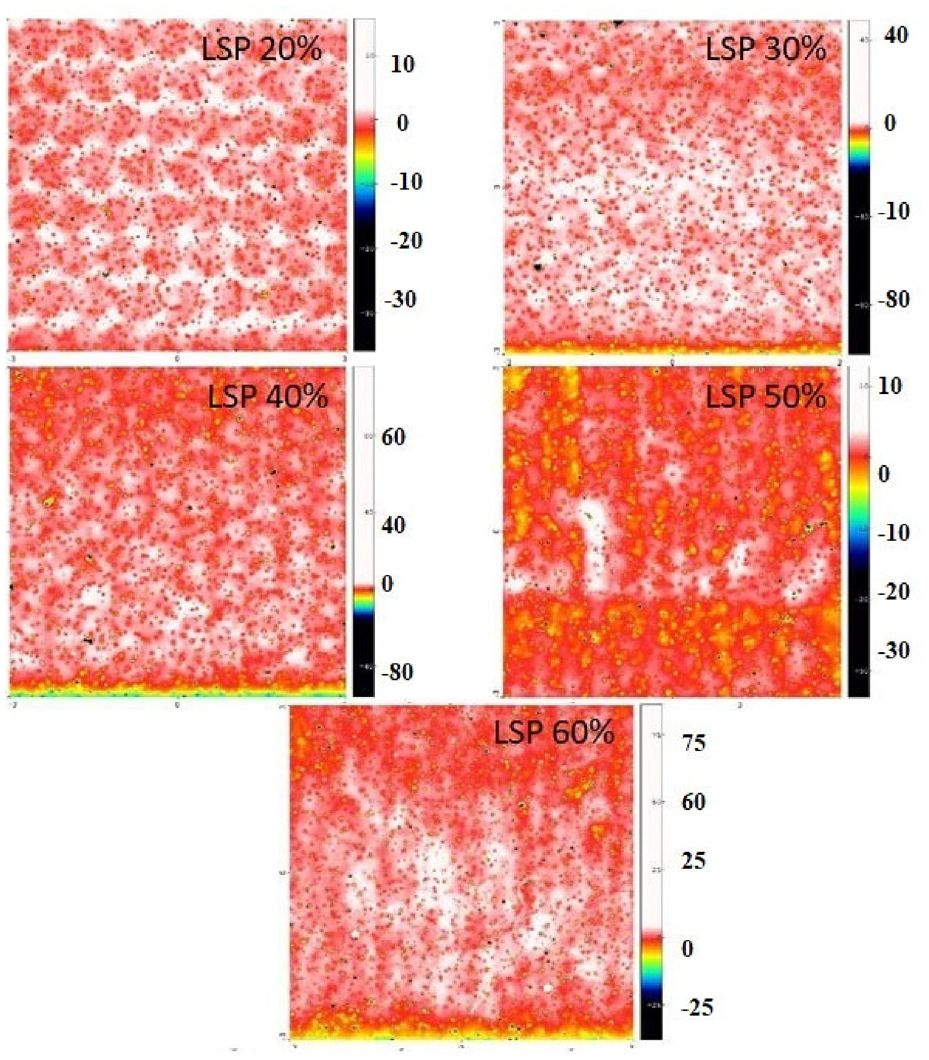
2D Scans for ADI samples laser shock peened with 20%, 30%, 40%, 50%, and 60% overlap and power intensity of 12.5 GW/cm2.
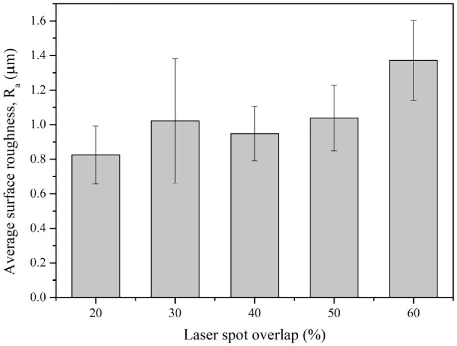
Average surface roughness of the laser shock peening treated specimens at different overlapping rates.
3D scans of the surfaces were carried out in order to see how the LSP affects the surface topography (Figure 10). The visible circular indents in all of the scanned samples represent the locations of the graphite nodules. The surface 3-D topography of the ADI, and laser shock peened ADI with a varying laser spot overlap from 20% to 60% in Figure 10 was analyzed such that comparisons of roughness following LSP could be done. The laser impacts on the surface are highly visible for the sample with a 20% laser spot overlap. However, as the degree of laser spot overlap was increased, the coverage by the spots was increased as well. Therefore, the peened area becomes less identifiable. As the overlap is increased, the scan also shows a higher coverage (identified in red, Figure 8). These impacts are generated by the local plastic deformation formed by the plasma-induced shock waves of the laser.
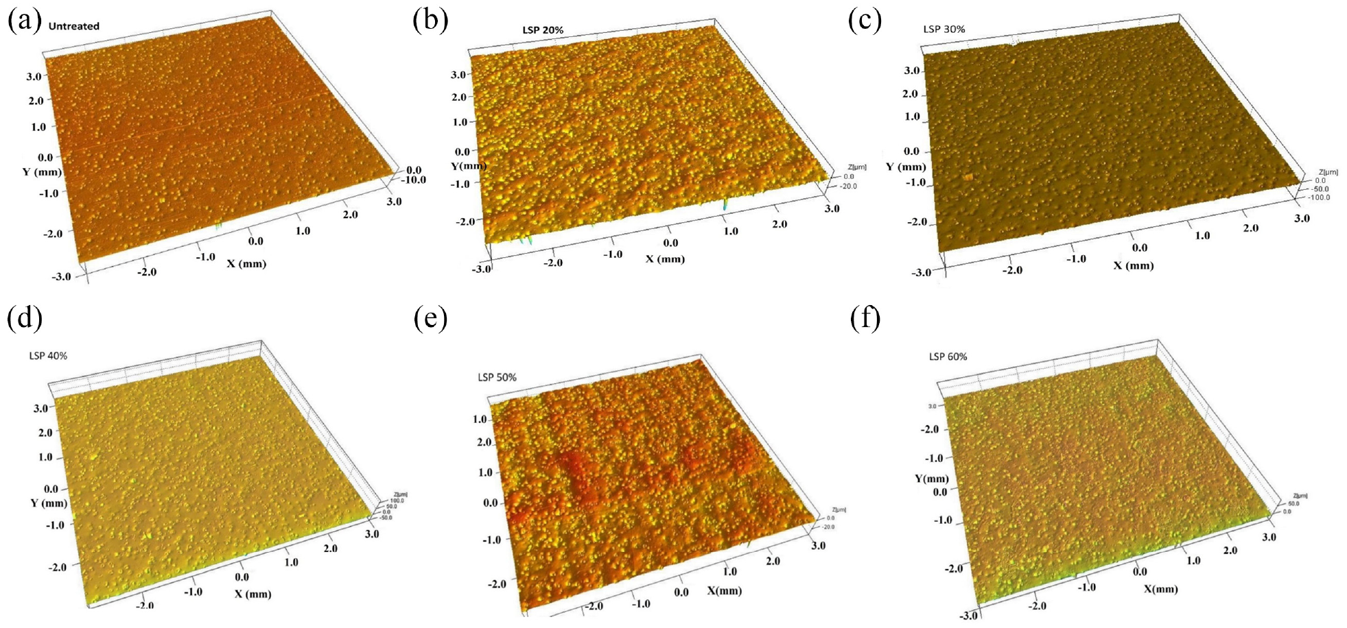
3-D surface morphology of (a) untreated austempered ductile iron and laser shock peened austempered ductile iron specimens at different overlapping rates: (b) 20%, (c) 30%, (d) 40%, (e) 50%, and (f) 60%.
Phase analysis
Following the microstructural analysis of the surface, the five samples laser shock peened with different overlapping rates were studied via X-ray diffractometry in order to identify any phase change due to the LSP treatment. All five samples produced the same peaks, with a graphite peak (002) (PDF reference no: 00-001-0640), 4 austenite peaks (111), (200), (220), and (311) (PDF reference no: 00-052-0513), and 5 α-ferrite peaks (110), (200), (211), (220), and (310) (PDF reference no: 00-006-0696), which can be seen in Figures 11 and 12. It can be noted that LSP did not result in any phase microstructural changes. 23
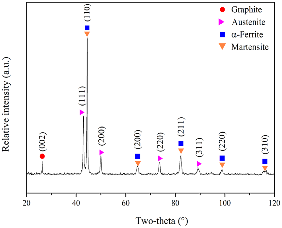
X-ray diffraction profile of the ADI specimen.
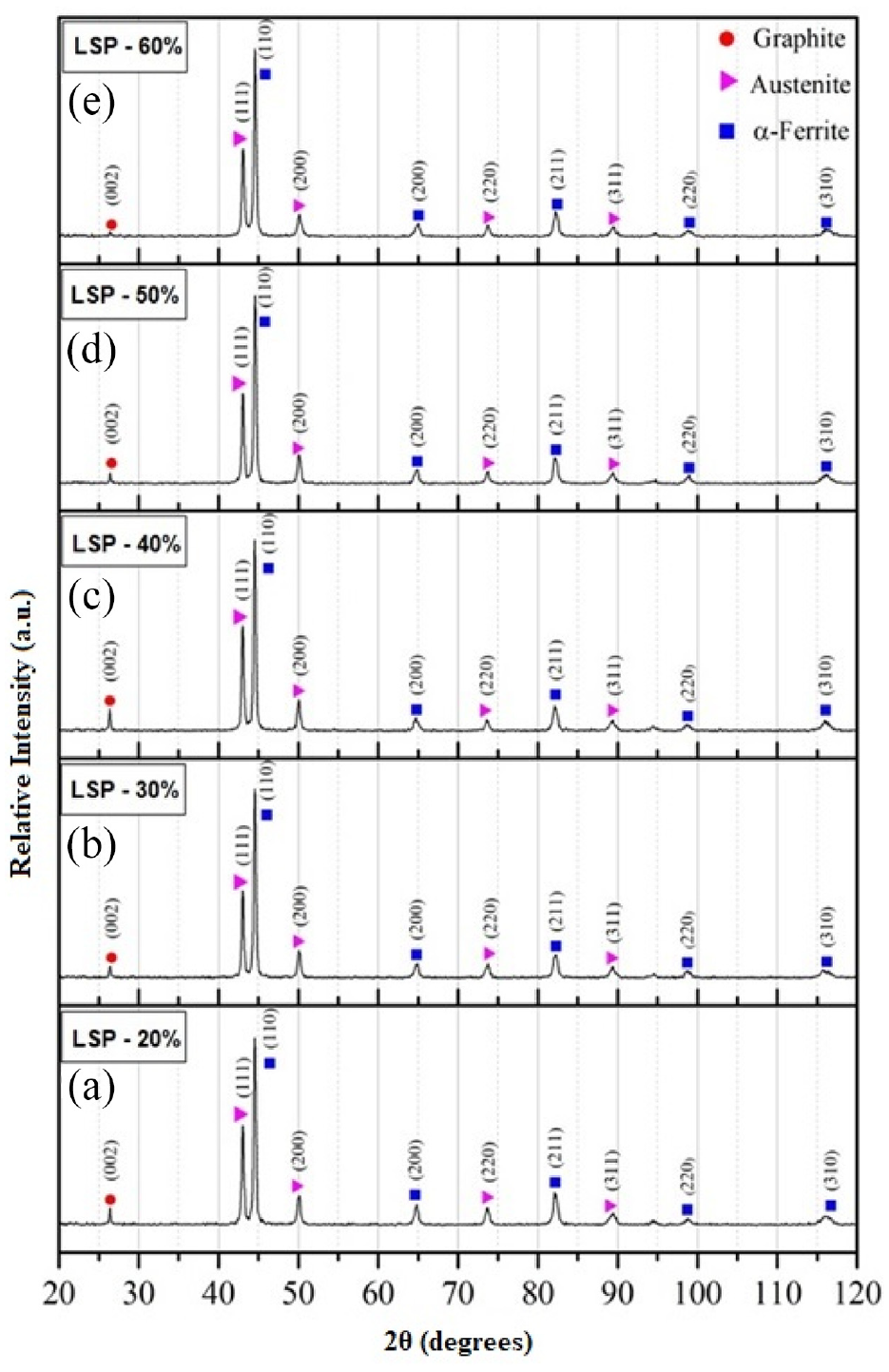
X-ray diffraction patterns for different laser spot overlapping rates: (a) 20%, (b) 30%, (c) 40%, (d) 50%, and (e) 60%.
Vickers microhardness analysis at different laser spot overlapping rates
Figure 13 shows the surface microhardness of the untreated and laser shock peened specimens. The 40% overlapped LSP treated specimens shows the highest hardness improvement. The hardness-depth profiling was carried out on the samples having a laser spot overlap varying from 20 to 60% and a fixed laser power intensity of 12.5 GW/cm2, as shown in Figure 14. The hardness ranges from the lowest value of approximately 392 ± 11 HV to the highest value of 449 ± 15 HV, achieved by the 20% laser spot overlap. An assessment of the hardness values obtained shows no statistically significant difference. Even though the phase transformation following LSP from austenite to martensite did not fully occur, an increase in hardness was still obtained after LSP. This can be attributed to the fact that a minor reaction between the laser shockwave and the ADI coupons still occurred during the surface treatment. This reaction is created near the surface of the target, formulating dislocations and microstructural changes. This increase in microhardness could also be due to the upsurge of dislocation densities as a consequence of the repetitive laser impacts on the target.
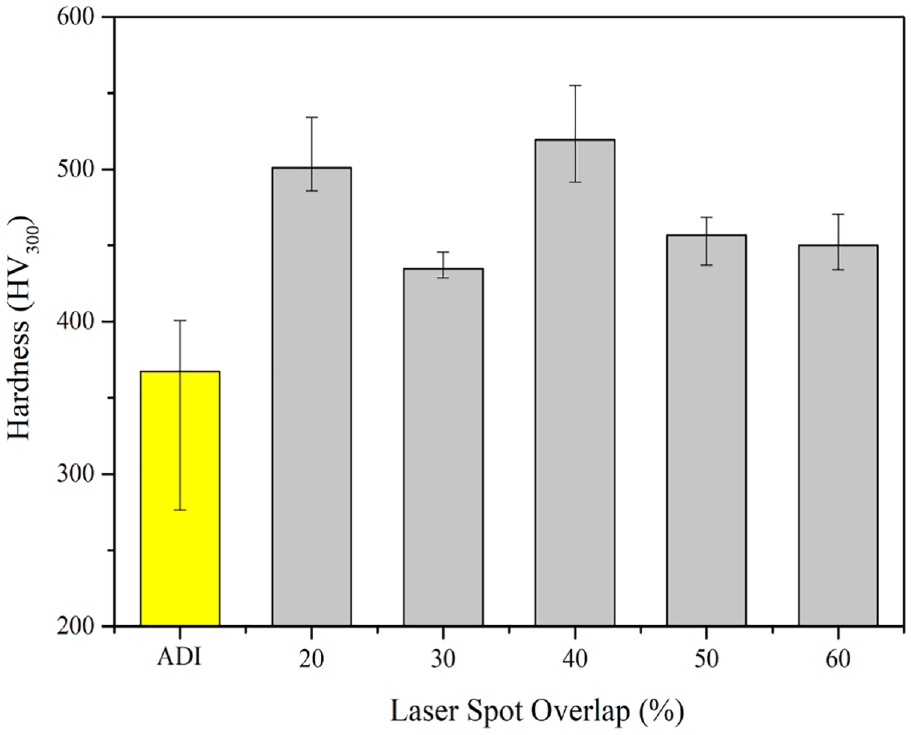
The Vickers microhardness on the surface of as-received ADI and laser shock peened treated at various degree of overlapping rates.
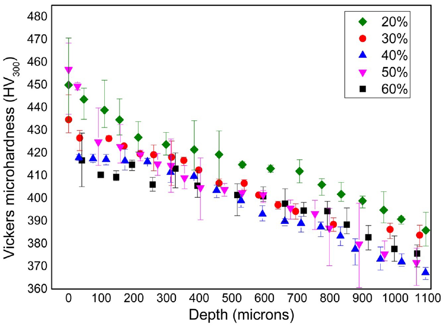
Vickers microhardness-depth profile for specimens laser shock peened with different overlapping rates.
In a similar study performed by Guo et al. 24 on magnesium alloys, an increase in hardness was observed after laser peening with a laser intensity of 13.5 GW/cm2 and varying laser spot overlaps from 0% to 50%. As the overlap was increased, an upsurge in hardness was obtained. However, no such correlation was found from this study. In this case, the hardness fluctuated until it consistently decreased at an overlap exceeding 40%, however this was related to black vinyl tape failure.
Conclusion
Laser shock peening (LSP) treatment of austempered ductile iron was carried out using a range of power intensities and spot overlap. The results presented in this work show that:
(a) Compressive stresses having a magnitude of 720 MPa were measured at the surface using the X-ray diffraction method, while the incremental hole drilling method measured compressive stressed ranging from −200 to −500 MPa to a maximum depth of 700 µm.
(b) An increase of 130% in the residual compressive stresses was seen when increasing the laser power density from 5 to 25 GW/cm2.
(c) The magnitude of the induced residual compressive stresses is lower than that obtained by shot peening (reported in other studies) of austempered ductile iron. This is attributed to the fact that LSP did not result in the austenite being transformed to martensite, as opposed to when shot peening austempered ductile iron.
(d) An increase in the surface roughness was noted when laser shock peening with spot overlap rates of higher than 40%, which is attributed to the tape failure.
(e) The effective power densities for the current laser pulse duration of 5.1 ns are far higher (12.5–25 GW/cm2) than the conventional laser power density values used at 532 nm (max 6 GW/cm2), which presents an emerging parameter space in the field of LSP process parameter development.
Considering the results obtained, the LSP treatment using a spot diameter of 1 mm, a laser power density of 12.5 GW/cm2 and 20% spot overlap significantly enhances the surface characteristics of the austempered ductile iron material by the induction of high and deep compressive residual stresses. Overall, this work shows that LSP may be ideally suited as a surface treatment during the engineering manufacture of austempered ductile iron products and components exposed to cyclic stresses such as automotive gears parts and aerospace components like turbine fan blades and landing gears.
Footnotes
Acknowledgements
The authors would like to acknowledge the positive impact of ERDF funding and the purchase of the testing equipment through the project: “Developing an Interdisciplinary Material Testing and Rapid Prototyping R&D Facility (Ref. no. 012).”
Declaration of conflicting interests
The author(s) declared no potential conflicts of interest with respect to the research, authorship, and/or publication of this article.
Funding
The author(s) disclosed receipt of the following financial support for the research, authorship, and/or publication of this article: In addition, the authors would like to acknowledge the project: “Setting up of transdisciplinary research and knowledge exchange (TRAKE) complex at the University of Malta (ERDF.01.124),” which is being co-financed through the European Union through the European Regional Development Fund 2014-2020.