
Abstract
The industry's demand for intricate geometries has spurred research into additive manufacturing (AM). Customising material properties, including surface roughness, integrity and porosity reduction, are the key industrial goals. This necessitates a holistic approach integrating AM, laser shock peening (LSP) and non-planar geometry considerations. In this study, machine learning and neural networks offer a novel way to create intricate, abstract models capable of discerning complex process relationships. Our focus is on leveraging the certain range of laser parameters (energy, spot area, overlap) to identify optimal residual stress, average surface roughness, and porosity values. Confirmatory experiments demonstrate close agreement, with an 8% discrepancy between modelled and actual residual stress values. This approach's viability is evident even with limited datasets, provided proper precautions are taken.
Keywords
Introduction
Aluminium alloy AlSi10Mg generally comprises 0.4 to 0.6 wt-% Mg and boasts various advantages. These include its lightweight nature, favourable mechanical properties, and low coefficient of thermal expansion (CTE), which contributes to its weldability and printability. 1 As an age-hardening alloy, it finds frequent application in die casting due to its desirable attributes such as hardness, strength-to-weight ratio, dynamic toughness and outstanding corrosion resistance.2,3 As industries strive towards miniaturisation by developing complex geometries and utilising lightweight materials to enhance overall productivity and performance of the end parts, additive manufacturing (AM) proves valuable in this regard by allowing swift design modifications without incurring additional expenses. 4 It expedites product development and shortens the time it takes to bring a product to market. This is achieved by minimising the time and costs involved in research and development through swift prototyping and effective design revisions, ultimately eliminating the necessity for expensive tooling. Despite these advantages, AM also presents certain limitations. These include compromised surface quality in terms of roughness and porosity, the presence of tensile stresses resulting from rapid heating and cooling cycles, reduced fatigue life, non-uniform material distribution that can affect the microstructure, and significant dimensional tolerances. 5 Various approaches of AM such as directed energy deposition (DED), plasma wire arc additive manufacturing (PWAAM), binder jetting (BJ), laser powder bed fusion (L-PBF), etc., amongst the mentioned processes L-PBF emerged as the go-to technology for most of the applications requiring a combination of precise deposition, good mechanical properties, and production of near net shape parts. But it also consists of some inherent limitations such as tensile stresses within the printed materials, sub-optimal surface roughness and may possess porosity due to gas evolution. Hence, in order to address these limitations and enhance the surface quality (including roughness and porosity) as well as the surface integrity (covering residual stresses, microhardness and microstructure) of components produced via L-PBF, various post-processing methods are employed. These methods encompass heat treatment, mechanical and chemical polishing, mechanical shot peening, sandblasting and laser shock peening (LSP). Amongst these techniques, LSP has gained prominence as the preferred choice for treating L-PBF parts, owing to its capacity to simultaneously improve both surface quality and surface integrity. 6 LSP overcomes material limitations by offering improved thermal management, increased fatigue life and the prevention of cracking, thus taking advantage of enhanced mechanical properties. 7
Machine learning (ML) has already proven useful in situations where complex relationships are present. 8 The obtained models offer representations with multiple levels of abstraction unattainable by traditional optimisation techniques. 9 Although ML approaches were already in use for decades, very limited amount of work have been done on optimising the LSP process in general, and especially for AM parts. Predicting the mechanical responses in additively manufactured AlSi10Mg specimens using ML has been published in Ref. 10 Much more robust work has been published regarding selective laser melting AM of A357 aluminium subjected to LSP using finite element method calculations and direct experiments in Ref. 11 The application of the ML approach has several advantages. Firstly, due to the complexity of the underlying physical processes, it is evident that a classical statistical approach would likely be difficult to implement in a pertinent manner, mostly due to the multidimensionality of the problem. In addition, since the dependence of the post-LSP material parameters on the laser processing parameters can be expected to be nonlinear, rather than attempting to detect appropriate regression functions by intuition, it is significantly more logical to use the inherent customisation features of the neural networks. 12 Although it would also be possible to attempt to execute a rigorous simulation based on traditional computational methods, this approach would be tremendously resource-intensive, both in terms of computational power and time. Due to the aforementioned reasons, the ML approach serves thus as an optimal first step towards process optimisation.
To create a platform and to fill the gap of limited studies in ML-based optimisation of LSP outcomes, the presented work is focused on utilising the full range of available laser parameters to identify the optimal values of the residual stress, average surface roughness, and porosity. The choice of thin-walled components aligns with current industry demands, particularly the drive for weight reduction in engineering applications. As geometries become more complex and curved, the practicality of processing narrow cavities from within diminishes significantly. This challenge reflects a real-world manufacturing scenario where access limitations can hinder conventional processing methods, highlighting the need for innovative solutions. The LSP process employed was used without the sacrificial layer which adds to the multidisciplinarity of the physics as the ablation and thermal effects of the laser cannot be ignored. Furthermore, the complexity of accurately predicting the response of such intricate structures, particularly with regards to residual stress, surface roughness and porosity, necessitates a fresh perspective. Traditional simulation approaches may prove impractical or computationally demanding when confronted with the intricate interplay between laser-matter interactions, L-PBF manufacturing, and the resulting structural characteristics. This intricate web of relationships becomes even more pronounced when considering the propagation of shockwaves within thin tubular geometries. 13 Consequently, this research introduces a novel and practical approach to address these multifaceted challenges in the context of AM and material property optimisation.
Materials and method
Tubular samples with an outer diameter of 12 mm and thickness of 2.75 mm were additively manufactured in a vertical orientation using a protective nitrogen atmosphere. The printing process was carried out on a Concept Laser M2 cusing machine, which is equipped with a continuous 400 W IR laser. The powder used in this study was CL31AL, provided by GE Additive. For the fabrication of the sample contours, a laser power of 200 W was employed, with a 50-μm round spot that moved across the build plate at a speed of 350 mm/s. The offset from the original contour was set at 0.175 mm. The core of the samples was printed similarly, but with a higher laser power of 370 W, a larger spot size of 190 μm, a faster speed of 1400 mm/s, and a trace spacing of 0.112 mm. Following the printing process, the samples underwent heat treatment, detachment from the build plate, characterisation and subsequent processing by LSP before final characterisation.
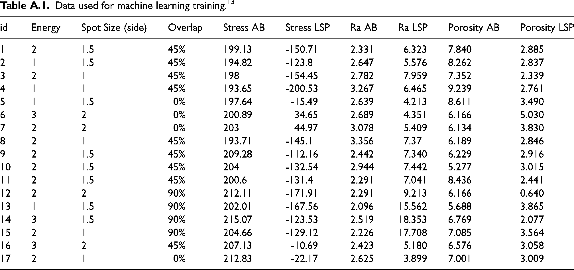
LSP was performed on the samples without a protective coating, the interaction of the laser is not limited to pressure waves, but the thermal and ablative effects are present. To create an optically transparent tamping layer, a thin 2 mm layer of water was used. The peening process was carried out using the Fanuc M-20iA/20 M robotic arm, which controlled the samples. The laser system employed in this study was the BIVOJ laser, operating at a wavelength of 1030 nm with a spatial square-shaped beam. The laser operated at a repetition rate of 10 Hz and had a pulse width of 14 ns with a square temporal profile. The peening strategy adopted in the experiment involved a spiral shape, with overlapping spots in both the x and z directions, as illustrated in Figure 1. A total of 17 experiments were performed by varying the three important parameters each at three levels, namely applied energy (ranging from 1 to 3 J), overlap percentage (ranging from 0% to 90%) and spot size (ranging from 1 to 2 mm). Throughout the experiments, the wavelength (1030 nm), repetition rate (10 Hz) and pulse width (14 ns) remained constant. The details of experimental details are presented in Table A.1. The experiment data was used for subsequent parameter optimisation using ML methods. Based upon the results of the exploratory data analysis, which involved testing of multiple machines learning models, ranging from classical linear regression, support vector machines and gradient-boosted trees to various neural network architectures, a standard feed forward neural network has been chosen as the primary model. The reason for this selection is the inherent ability of the neural network to predict all output variables at once, thus additionally leveraging the relationship between the output variables themselves.
Schematic of laser shock peening.
As input data, in the present work the laser processing parameters, i.e. energy, spot size and overlap and as-built stress, average surface roughness and porosity were used, whilst the output dataset consists of residual stresses, roughness, and porosity. Residual stresses were measured using the Rigaku AUTO-MATE II X-ray diffraction machine using
Utilising ML models presents certain challenges, especially when working with limited and unique datasets. In our case, each data point in the experimental dataset has distinct features, making traditional evaluation methods like the conventional train-test split impractical. Through k-fold cross-validation, we observed that excluding any data point from the training set profoundly impacts the model's inferencing ability. Consequently, we trained the model on the entire dataset, cognizant of potential overfitting. To enhance the model's validity, we imposed physical constraints on the variables, ensuring attributes such as the positivity of energy. Given our primary focus on interpolation, the risk of overfitting is further mitigated. The final neural network is a result of careful experimentation with different architectures. Since the objective is a fairly straightforward regression task, it is not necessary to build a deep network, especially with the looming threat of overfitting.
The data processing and the training of the neural network were performed using the standard backpropagation algorithm
8
with the Adam optimizer
14
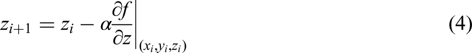
in the keras and scikit-learn python libraries. The resulting model has been used to calculate and interpolate the values in the design space as presented in Figure 3. Obtaining the optimised parameters for LSP treatment is essentially a task to calculate the argmin (Stress LSP). To that effect, we have implemented a gradient descent algorithm, which was subsequently applied to the trained neural network. If we denote the Stress LSP as f, energy as x, spot size y and overlap as z, the algorithm can be written as presented in equations (1)–(4).
Results and discussion
Amongst different tested approaches for the neural network architecture, the setup consisting of three layers as described in Figure 2 has shown to produce the best results. The resulting model has been used to calculate and interpolate the values in the design space as presented in Figure 3. In the ML developed design space, the calculated minima and maxima of the output parameters are (-260.8 to -46.8 MPa) in terms of residual stress as depicted in Figure 3(a), (2.00–21.12 μm) in terms of average surface roughness “Ra” as presented in Figure 3(b). The roughness has increased in every combination of processing parameters as compared to the initial value after printing due to thermal and ablation connected effects, which are not being eliminated via the use of sacrificial coating. Reduction of porosity has been achieved in the range (18.3–100%) as shown in Figure 3(c). The parameters where the theoretical maximum reduction of porosity is reached however correspond to the moderate amount of approximately −100 MPa of residual stress and the malignant effects of the combination of high energy and high overlap which resulted in the loss of structural integrity in the conducted experiments due to ablation and related phenomena.
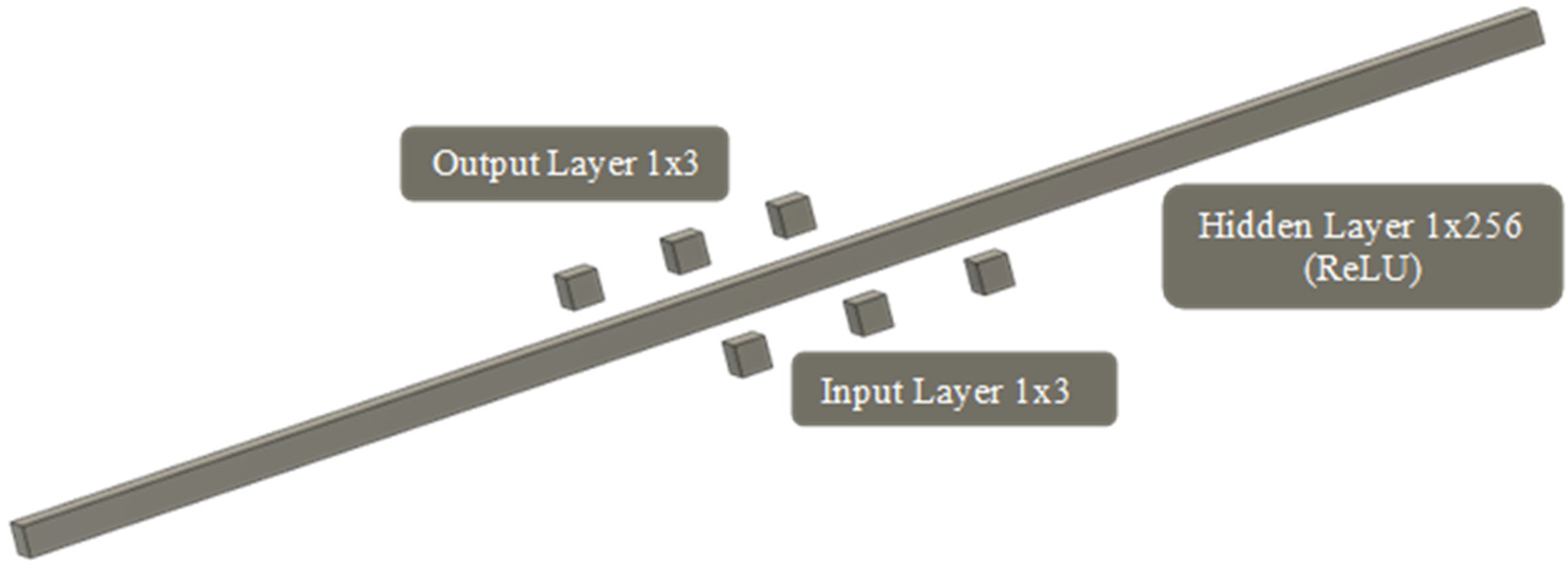
Architecture of the neural network.
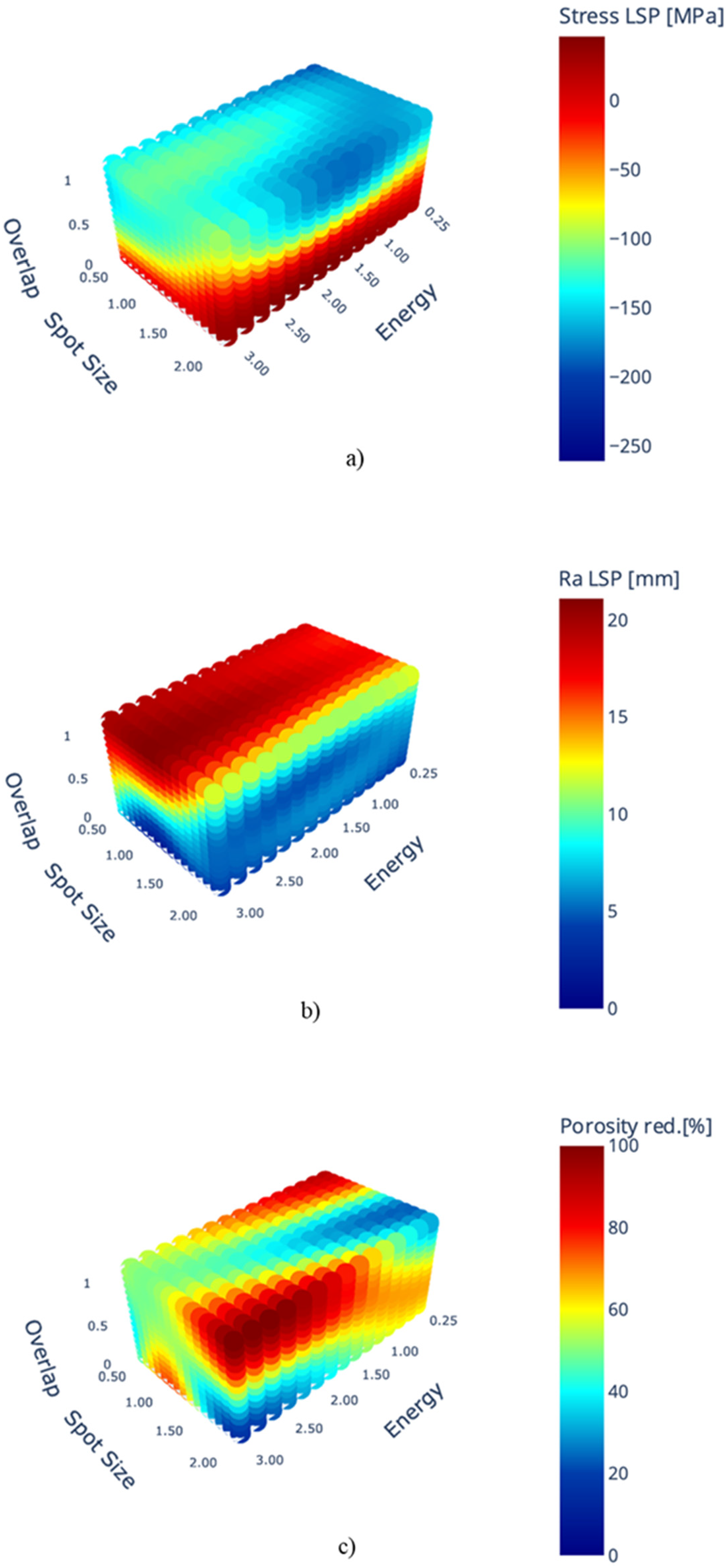
Modelled responses in the design space consisting of pulse energy, overlap and spotsize: (a) surface residual stress, (b) roughness Ra and (c) volume of porosity reduction.
The ML developed design space and model trained to predict the lowest possible value of residual stress, within the range of LSP parameters as presented in Figure 3(a–c). The model predicted that use of 0.25 J as energy; 0.67 mm2 as spot area; and 55% as overlap can provide the lowest value of residual stress, i.e. −260.8 MPa. To validate the model a confirmation experiment was conducted, the details of the confirmation experiments are presented in Table 1, along with the measured responses. The data exhibited in Table 1, proves close agreement between the model predicted and experimental finding of the residual stress, and lies within the uncertainty of the measurement.
Details of model predicted and confirmation experiment.
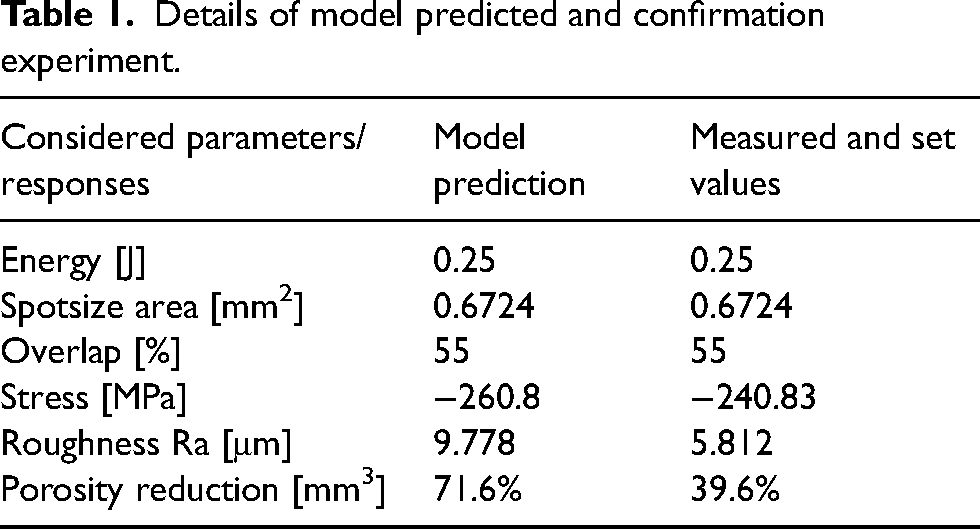
The value of residual stress was the key factor with the focus for prediction. In terms of roughness parameter Ra, the measured value is lower than predicted. This is beneficial from the industrial point of view as lower roughness is regarded beneficial in almost all scenarios. From the ML point of view, this can be regarded as room for improvement of the modelled response, however as mentioned above, the main considered goal for prediction has been the value of residual stress. The prediction of porosity reduction might seem unsatisfactory; however, the amount of porosity varies significantly across all samples (as presented in Table A.1) and the sample before LSP processing showed below average amount of 4.96 mm3 of traced porosity in the evaluated volume compared to the average volume of 7.0 mm3. When combined with the fact that the porosity is not spread evenly across the volume of the sample but is concentrated near the inner and outer surfaces of the sample, the comparison of the model prediction and measured value should be discussed with these considerations in mind. As presented in Figure 4, where the porosity is divided into classes of equal volume and transferred to cylindrical coordinates, the porosity is concentrated in classes representing the transition from the skin and core printing strategies.
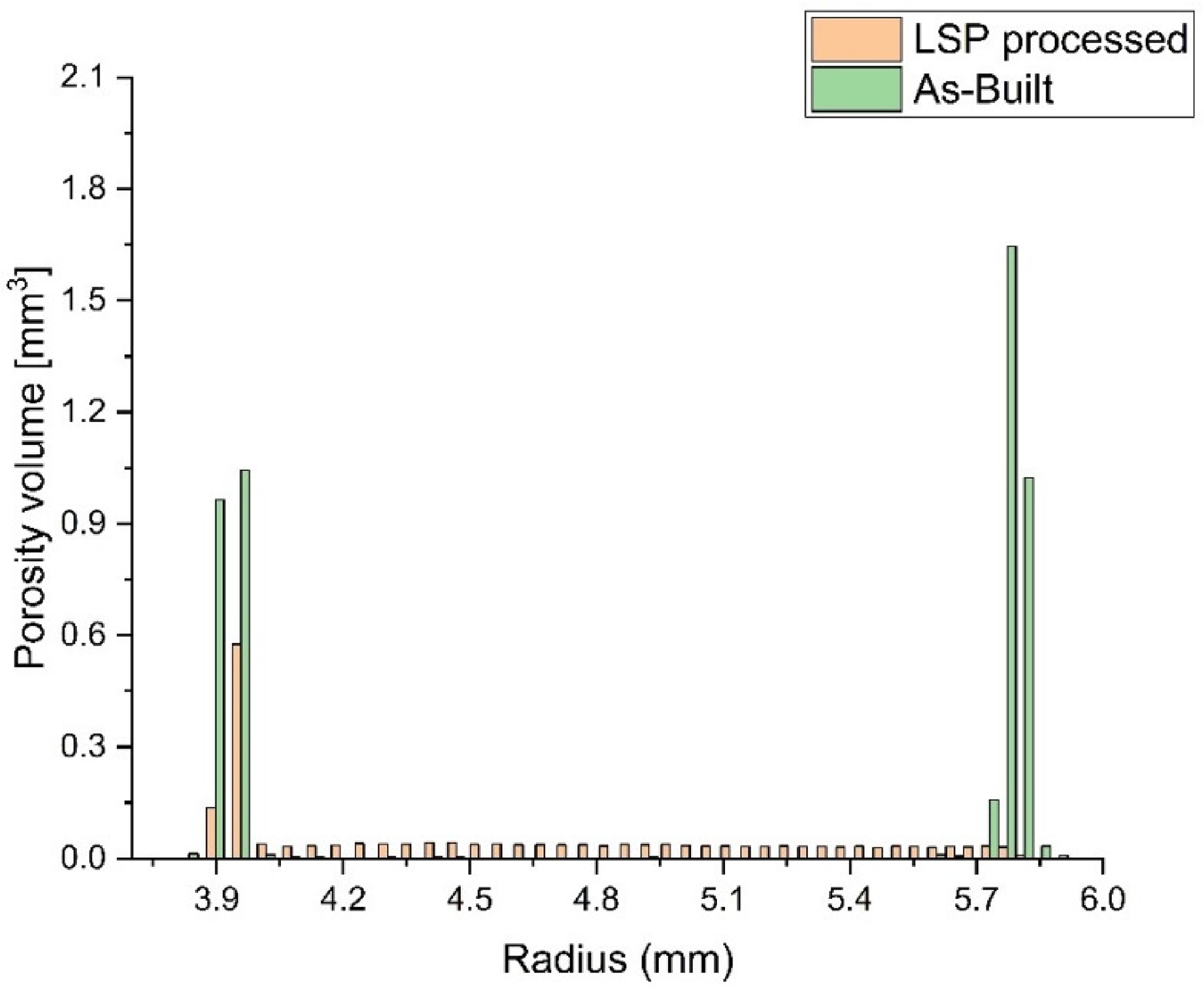
Distribution of porosity in the sample.
Following the discussion about disproportionate distribution of porosity, the LSP process is effective in closing the porosity or reducing it below the detection threshold of the tomography machine mainly nearing the outer edge of the sample, as visible from Figures 4 and 5, where in Figure 5 the porosity is highlighted with yellow arrows. The areas nearing the inner edge of the sample do not show as effective pore closure effect as nearing the outer edge of the sample, as manifested in Figure 5, due to the attenuation of pressure waves and destructive wave interference created by wave reflection from the inner surface. The porosity closing effect of the processing is also visible in Figure 6 where the 3D view of the sample before and after LSP processing with reduced opacity is presented. Further research and refinement of the models are warranted to enhance their predictive capabilities and overall utility in real-world manufacturing scenarios.
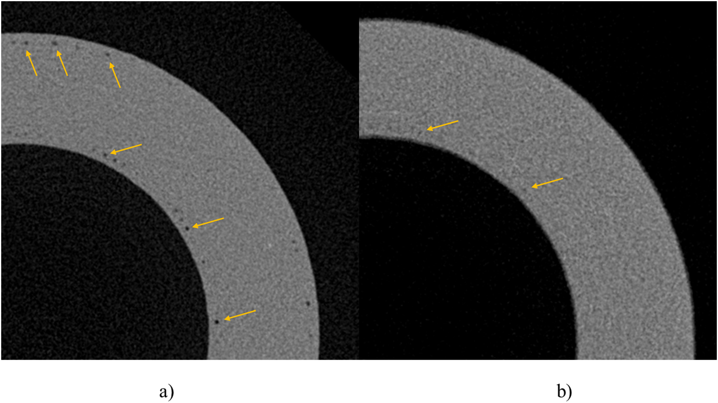
Cross-sectional view obtained through computed tomography (a) before LSP processing and (b) after LSP processing (porosity is highlighted with yellow arrows).
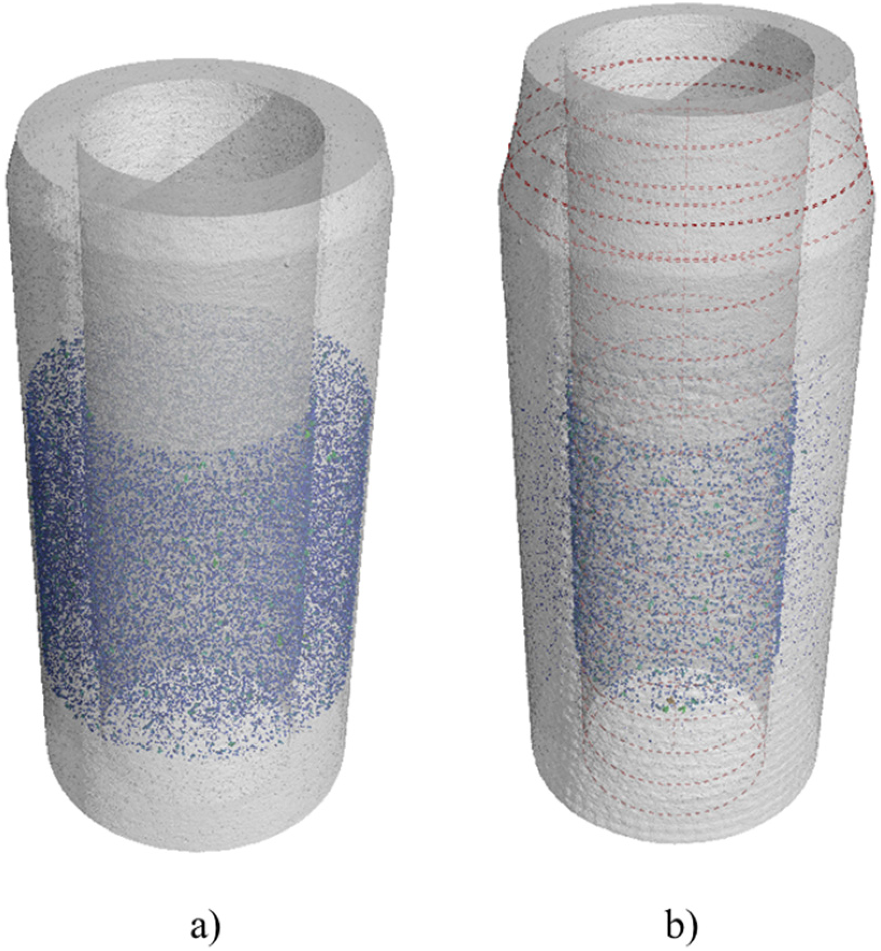
Isometric view obtained through computed tomography (a) before LSP processing and (b) after LSP processing (the base material is set to 70% opacity and the detected porosity is highlighted in blue).
Conclusions
The study's conclusions provide insightful information and important inferences that can be made are:
This study convincingly demonstrates the feasibility of constructing a robust ML model and design space that effectively captures the intricate interactions between LSP parameters and responses. Notably, the model accurately predicted parameters such as energy (0.25 J), spot area (0.67 mm²) and overlap (55%), showcasing close agreement with the modelled value (i.e. -260.8 MPa) observed values (i.e. -240.8 MPa) of residual stresses. However, it is crucial to note that the model faced challenges in predicting roughness and porosity, primarily attributed to the intricate thermal and ablation effects inherent in the laser peening with coating (LPwC) process. It was noticed that the porosity and roughness of the LPwC processed samples were reduced by 39.6% as compared to the model predicted 71.6%, whereas, The actual roughness value measured at 5.4 μm, in contrast to the model's projection of 9.7 μm. These findings align with the lower initial values of porosity and roughness identified during examinations. In conclusion, this study emphasises how ML may be used to model and improve intricate industrial processes. Even if the results are encouraging, it is critical to recognise the dataset's limitations, which indicate the need for additional research and validation in larger-scale applications.
Footnotes
Acknowledgements
This work was supported by the infrastructure of the Centre of Advanced Aerospace Technology, Project No. CZ.02.1.01/0.0/0.0/16_019/0000826 and project SGS22/158/OHK2/3T/12 Faculty of Mechanical Engineering, Czech Technical University in Prague.
Declaration of conflicting interests
The authors declared no potential conflicts of interest with respect to the research, authorship and/or publication of this article.
Funding
The authors received no financial support for the research, authorship and/or publication of this article.
Appendix A
Data used for machine learning training. 13
| id | Energy | Spot Size (side) | Overlap | Stress AB | Stress LSP | Ra AB | Ra LSP | Porosity AB | Porosity LSP |
|---|---|---|---|---|---|---|---|---|---|
| 1 | 2 | 1.5 | 45% | 199.13 | -150.71 | 2.331 | 6.323 | 7.840 | 2.885 |
| 2 | 1 | 1.5 | 45% | 194.82 | -123.8 | 2.647 | 5.576 | 8.262 | 2.837 |
| 3 | 2 | 1 | 45% | 198 | -154.45 | 2.782 | 7.959 | 7.352 | 2.339 |
| 4 | 1 | 1 | 45% | 193.65 | -200.53 | 3.267 | 6.465 | 9.239 | 2.761 |
| 5 | 1 | 1.5 | 0% | 197.64 | -15.49 | 2.639 | 4.213 | 8.611 | 3.490 |
| 6 | 3 | 2 | 0% | 200.89 | 34.65 | 2.689 | 4.351 | 6.166 | 5.030 |
| 7 | 2 | 2 | 0% | 203 | 44.97 | 3.078 | 5.409 | 6.134 | 3.830 |
| 8 | 2 | 1 | 45% | 193.71 | -145.1 | 3.356 | 7.37 | 6.189 | 2.846 |
| 9 | 2 | 1.5 | 45% | 209.28 | -112.16 | 2.442 | 7.340 | 6.229 | 2.916 |
| 10 | 2 | 1.5 | 45% | 204 | -132.54 | 2.944 | 7.442 | 5.277 | 3.015 |
| 11 | 2 | 1.5 | 45% | 200.6 | -131.4 | 2.291 | 7.041 | 8.436 | 2.441 |
| 12 | 2 | 2 | 90% | 212.11 | -171.91 | 2.291 | 9.213 | 6.166 | 0.640 |
| 13 | 1 | 1.5 | 90% | 202.01 | -167.56 | 2.096 | 15.562 | 5.688 | 3.865 |
| 14 | 3 | 1.5 | 90% | 215.07 | -123.53 | 2.519 | 18.353 | 6.769 | 2.077 |
| 15 | 2 | 1 | 90% | 204.66 | -129.12 | 2.226 | 17.708 | 7.085 | 3.564 |
| 16 | 3 | 2 | 45% | 207.13 | -10.69 | 2.423 | 5.180 | 6.576 | 3.058 |
| 17 | 2 | 1 | 0% | 212.83 | -22.17 | 2.625 | 3.899 | 7.001 | 3.009 |