
Abstract
Present work aims to study the fatigue life behaviour of additively manufactured (AM) stainless steel 316L in a laser shock peening (LSP) process. The fatigue behaviour of as-built samples and LSPeened sample were studied on the AM samples. A new diode-pumped laser system was utilized as an instrument to perform LSP operations. LSP operation was performed under two different sacrificial layers of different materials i.e. vinyl tape and aluminium tape. The other essential LSP parameters, namely energy, pulse width, spot size, overlap, and number of layers were kept constant based on the previous experimental findings. The characterization was done for analyzing the residual stresses using a hole drilling process, and a 4-point bending machine. A considerable improvement in compressive residual stress and fatigue life was observed in the LSPeened samples. Such improvements in residual stresses and fatigue life may pave a road to establishing diode-pumped lasers for LSP applications.
Introduction
Additive manufacturing (AM) or free form manufacturing has brought enormous benefits to mankind. AM has already shown its usefulness in various medical and engineering applications [1,2]. Metal additive manufacturing (MAM), which fosters the development of smart technologies and production systems, is one of the essential pillars of industrial revolution 4.0. But, AM-produced parts are still not able to demonstrate desirable mechanical properties, especially for aerospace and biomedical engineering industries.
Among various types of AM, Selective Laser Melting (SLM) is the most investigated since it utilizes all required capabilities of today's industry on a relatively extensive range of metals and alloys. SLM is especially attractive in the biomedical industry to produce customized patient's anatomy prosthetics. During SLM, laser heat was selectively used to melt successive layers of metallic powder in specific places on a metallic powder bed. Consequently, the parts manufactured by SLM may have inherent defects such as voids, porosities, incomplete fusion holes, cracks, metallic inclusions, segregations, and metallurgical imperfections, while the remaining tensile stresses are resulting in a shape distortion [3]. Therefore, to improve the quality of the AM parts, different post-processing techniques such as surface finishing/polishing, shot peening (SP), sandblasting were usually used by the industries and researchers. However, polishing and relieving tensile residual stresses is insufficient to meet the required performances [4], particularly in improving fatigue life. Various methods can be used to reduce the tensile residual stresses in SLM manufactured parts, and these methods can be divided into in-situ control and post-process control methods [5]. In-situ control we can classify as in-situ feedback control, thermal gradient control, scanning strategy control, and mechanical control [4-6]. Post-process methods include post-heat treatment, post-annealing, machining, magnetic field-assisted finishing, SP, laser shock peening (LSP), etc. [3,4,6,7-11]. In recent times, LSP has emerged as a possible solution for enhancing the fatigue life of the components, and it has been in research to utilize the LSP benefits to the AM manufactured parts.
LSP is a surface enhancement process used to deform material plastically and impart beneficial compressive residual stress into the material. The high amount of compressive residual stresses, deeply imparted into the material, increases the material resistance to failures. Typical failures that can be postponed or prevented are material fatigue, crack growth, or stress corrosion cracking [7,8]. LSP consists of four stages: (i) delivery of a laser beam with defined energy; (ii) plasma generation on the material's surface under the confining medium (the confining medium is critical in preventing plasma from expanding away from the surface and generating strong high-pressure shock waves); (iii) propagation of high-pressure waves in the materials; and (iv) plastic deformation and generation of compressive residual stresses inside the material [1-6]. Figure 1 depicts a schematic of the LSP process.
LSP process [14].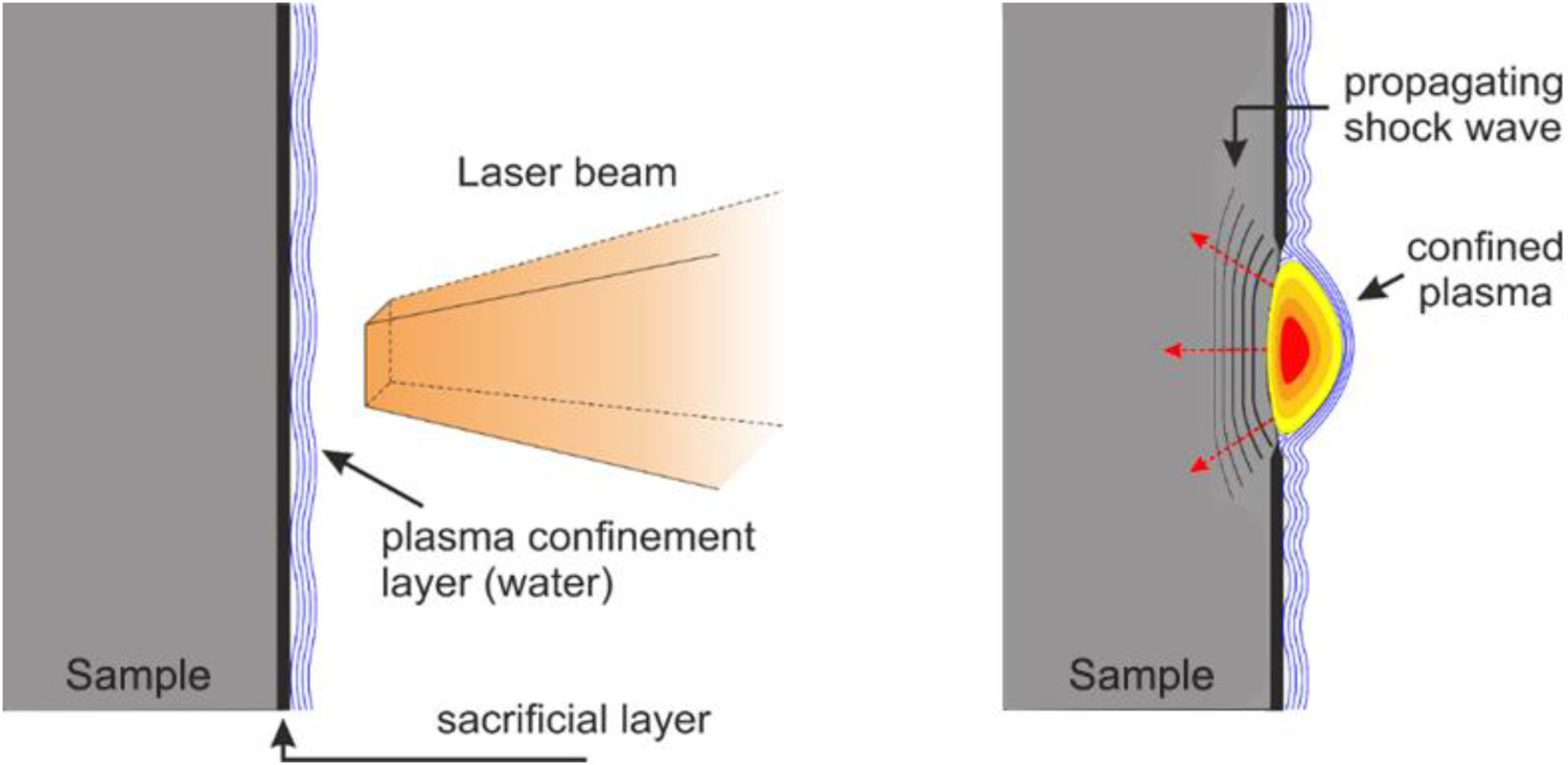
Absorbent coating or sacrificial layer used in the process helps prevent the materials melting and laser ablation while maintaining the surface quality [9]. By preventing the melting of the target, the formation of tensile stresses on the surface can be avoided. Higher stresses than plasma pressure can be generated in the material by using a substantial sacrificial layer with low acoustic impedance relative to the sample material [9,10].
As mentioned, LSP has been extensively used to improve the AM parts. Kalentics has demonstrated in his PhD theses [11] that LSP can be used as an in-situ control method of reducing tensile residual stresses in parts fabricated by SLM. Moreover, he proved that LSP could transform the tensile residual stress into compressive residual stresses in SLM parts. This approach is based on applying LSP each time after a few newly printed layers. The main disadvantage of this approach is the lack of lasers with suitable size, parameters (with a good ratio between the energy and the repetition rate), and price, which could be used in this hybrid process. However, the lasers suitable for the LSP as a part of this hybrid process are becoming cheaper while offering the parameters (mentioned above) suitable for this application [13]. It is expected that this hybrid process could become the primary tool for improving the mechanical properties of SLM fabricated parts in the future. LSP can also be applied as a post-process method [14-16]. So far, a few articles have been published with the demonstration of the LSP as a post-process tool [3,4,9-12,17,18].
In this paper, LSP has been applied as a post-process method for improving the AM parts using the J-level laser system [19], i.e. BIVOJ, which is based on the new diode pump technology where the Yb:YAG material has been utilized. The experiments were done at the fixed levels of LSP parameters, and residual stresses and fatigue life were considered responses. The present experiments may help the Yb:YAG diode pump laser system prove capabilities and recognize this system's limitation for LSP as a post-process tool in AM production.
Sample materials and geometry
Extraordinary characteristics, especially high corrosion resistance, promote the extensive application of 316L stainless steel in many industries, such as aerospace, biomedical, chemical, and pharmaceutical. Considering the wide range of sectors where 316L is used, it is understandable that 316L steel is attractive for additive manufacturing.
The geometry and size (length 120 mm; width 12 mm; height 21 mm) of samples are the same as the ones used in [4]. Samples were tapered to 5 mm on the gauge section with a 2.5 mm radius as depicted schematically in Figure 2(a) and photograph of the sample in Figure 2(b). This samples configuration provides ease in geometrical complexity and allows uniform LSP processing and stress loading [4].
Schematic of (a) cross-section of the sample and photograph of (b) produced sample with a fabricated notch.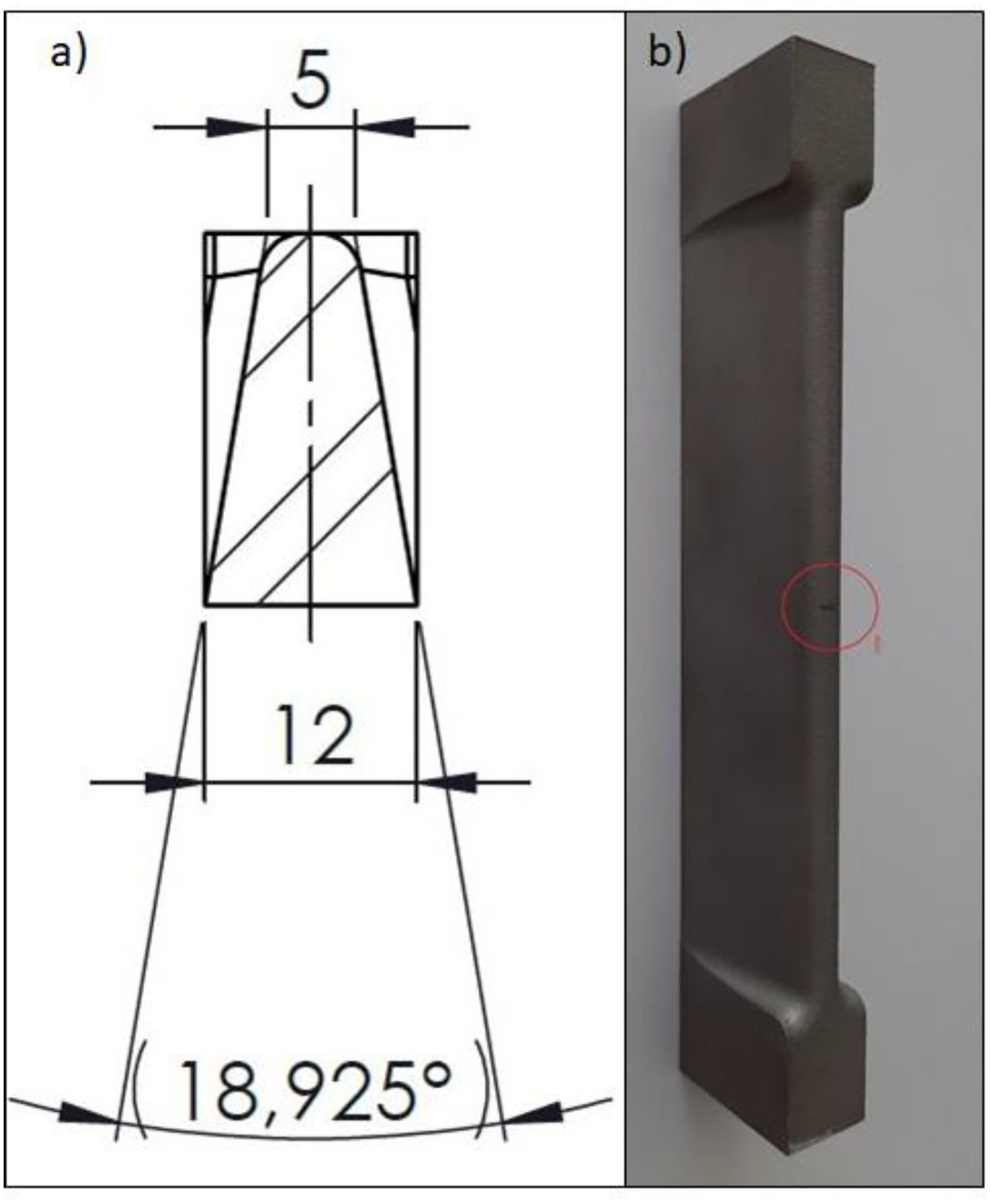
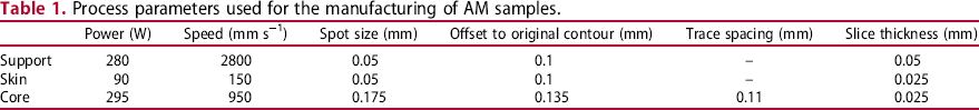
Process parameters used for the manufacturing of AM samples.
Process parameters used for the manufacturing of AM samples.
After fabrication, a notch was machined by the electric discharge machine on each sample. The notch was 300 μm in width and 350 μm deep, Figure 4(b). The addition of the notch creates the stress riser, resulting in breaking the sample during the fatigue testing on the line of the stress riser, notch. Furthermore, adding the notch, the stress riser, allows us to test the inherent performance of the AM material since AM materials after the fabrication typically shows worse surface conditions and have more material inclusions and voids, compering to the traditionally produced materials [4].
Samples were LSP processed with laser parameters energy of 4 J, square spot size of 3 mm × 3 mm size, and pulse width of 10 ns. The equivalent power density was 4.4 GW cm−2 (see Table 1). The processing has been performed at HiLASE premises in the laboratory designed and dedicated to LSP research and development. The experimental set-up is illustrated in Figure 3. For this experiment, we used a BIVOJ laser [19] with an essential feature of the top-hat beam with a square shape that enables reasonable control of the LSP processing. While the laser beam is spatially fixed, the robotic arm moves the treated sample over a pre-defined path to affect the desired area. More details about the HiLASE LSP set-up can be found in [14].
Schematic representation of the experimental set-up.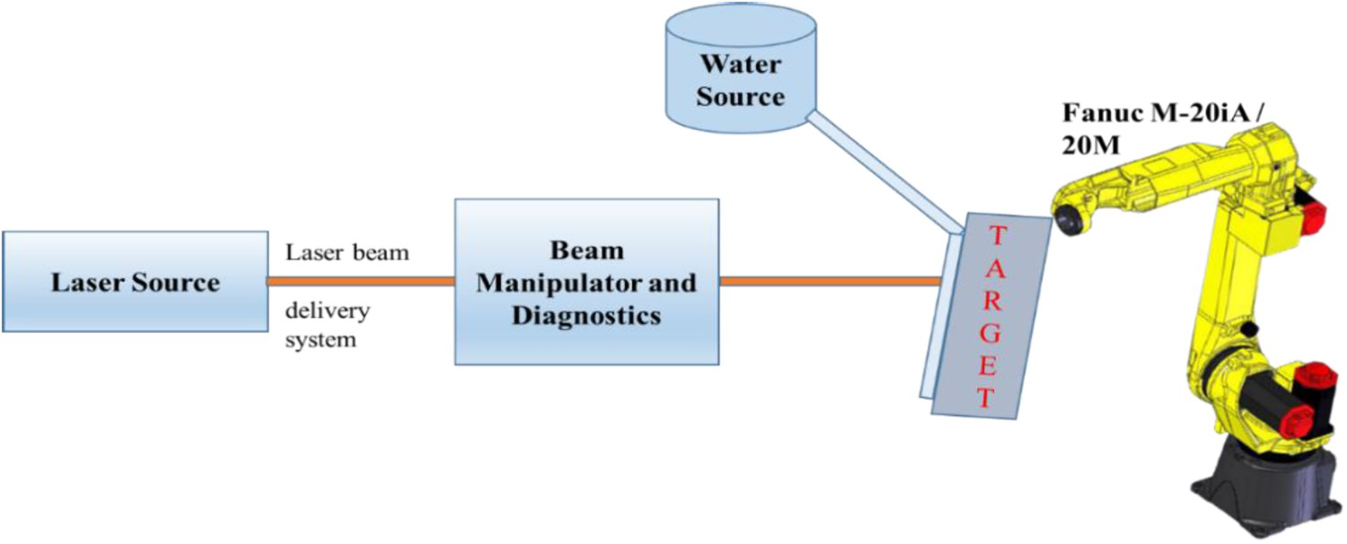
Samples were laser peened in the central part as presented in Figure 4(a,b), with parameters providing the same incident laser power density as in [4] (see Table 2). Four samples were treated with vinyl tape (VT), and the remaining four samples were treated with aluminium (AlT) tape as the sacrificial layer. The VT, a product of the 3M company, used in the experiment was 130 μm thick. This tape is widely used in LSP processing. The AlT, a product of PPI Adhesive Products Limited, was 90 μm thick. This tape is commonly used for the plasma cold spraying process. In further text, the LSP process with aluminium tape is referred to as AlT, while the vinyl tape is referred to as VT. The LSP patch was created over the cone area, curvature, and 6 mm down the curvature along the side, as depicted in Figure 4(b).
Photograph of (a) creation of LSP patch and (b) samples prepared for fatigue testing. LSP parameters used for the processing.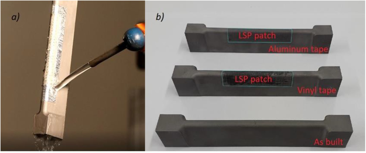
Residual stress measurements and fatigue testing were carried out on three types of samples: as-built (AB), LSP processed with VT, and AlT as the sacrificial layer. The details of the characterization techniques used are presented in the following subsections.
Residual stress measurements
The residual stresses were measured using the hole drilling method with the ‘Prism’ hole drilling machine produced by the company ‘Stresstech’. The hole drilling method of ‘Prism’ is based on the measurements of surface distortion caused by the drilling using electronic speckle pattern interferometry. The drill diameter was 1.6 mm, and it enabled measurements to 1 mm, while the rotation speed of the drill was 40,000 rev min−1.
Fatigue life testing
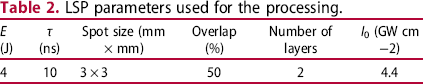
After the LSP processing, the fatigue life testing was carried out on a 4-point bending machine. The testing was done on four AB samples, four samples processed with a VT process, and four processed with an AlT process. A resonant test rig of 250 kN was employed for the testing (Figure 5(b)). The samples were loaded sinusoidally with a stress ratio R = 1. The loading and support spans were designed and adjusted according to the total length of samples. The support span L was set to 105 mm. According to this adjustment, the load span was set to 35 mm, as shown in Figure 5(a). For the testing, the stress loading was from 350 to 500 MPa.
Schematic of (a) 4-point bending test loading scheme and photograph of (b) 4-point bend test rig RUMUL.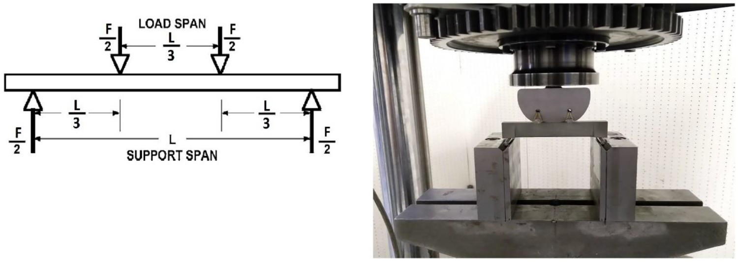
The value of up to 54.9 MPa has been measured at the subsurface part of the SLM manufactured AB sample. For the AB sample, the residual stresses are in a tensile regime (see Figure 6). The residual stresses constantly remain in the tensile regime to the depth of 1 mm. After the AM process, the tensile regime of residual stresses is not unusual. Although the stress relief process was applied after the fabrication of samples, the tensile stresses were not eliminated.
Residual stress distribution for AB, AlT, and VT.
LSP processing with parameters given in Table 2 changes the state of residual stresses in the samples from tensile to the compressive regime for both applied tapes. The highest value of compressive residual stress at a depth of 0.05 mm was measured to be –638 and –582 MPa for AlT and VT, respectively. The last residual stress measurement was made at 1 mm depth for both samples, with measured values –39 and –106 MPa for AlT and VT, respectively.
The load stress values chosen for the fatigue testing were 350, 400, 450, and 500 MPa, as presented in Figure 7. For both types of LSP processed samples (i.e. AIT and VT), the prolongation of fatigue life compared to samples that were not peened has been achieved. The lifetime improvement was from 1.8 to 4 times. For the highest 500 MPa load, the improvement for both types of LSP treated samples was similar, 1.8 times for the AlT and 1.9 times for the VT. On the other hand, for the 450 MPa load, the VT samples have shown significantly better results, 4 times improvement compering to 1.9 times improvement for the AlT sample. For lower values of load stress, the improvement was similar for VT and AlT samples. However, on average, the VT samples have shown slightly better results, and this can be attributed to a bit higher compressive residual stresses deeper in the material. The obtained results can be justified with the micrographs presented in Figure 8 and the following discussion.
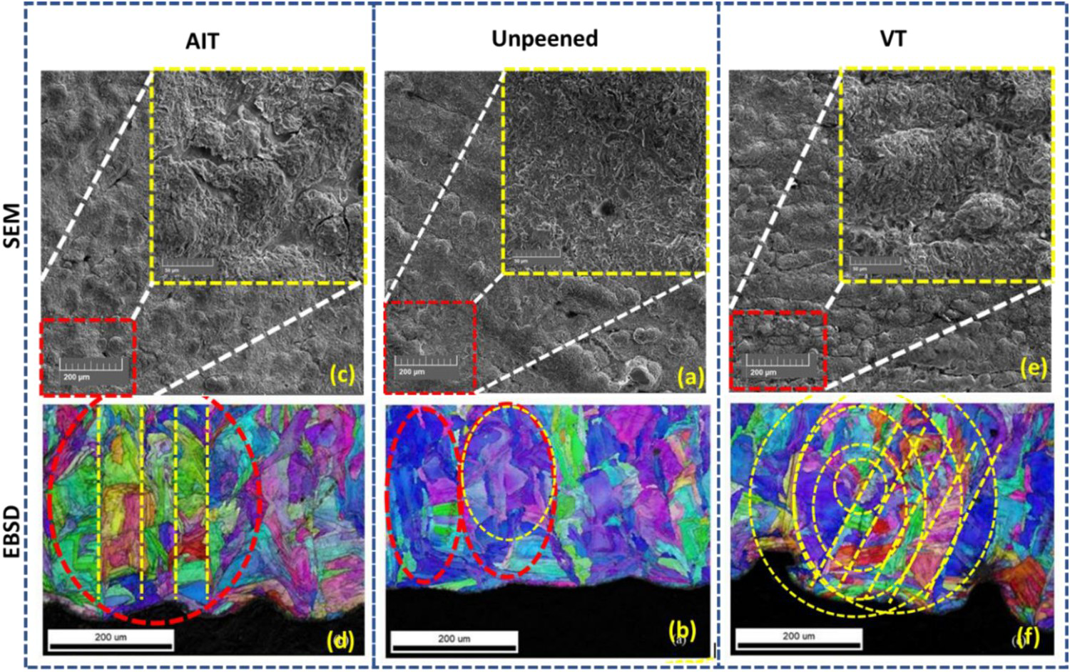
Graphical representation of the fatigue test results. (a,c,e) The SEM micrographs of unpeened, LSP treated with AIT, and LSP treated with VT, respectively. (b,d,f) EBSD micrographs of the same three samples.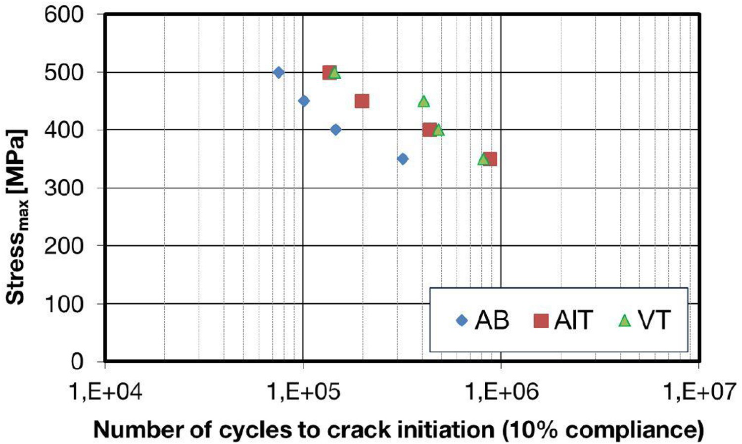
The SS316 steel is in the category of Austenitic Steel. The Austenitic steel is of FCC-type crystal structure. The average bond length of a unit lattice is nominated by ‘a’ and it is a = 3.5 Å. The ‘a’ is approximately 0.3 nm. This signifies that a grain of average size 200 µm is comprised of several lattice structures. Therefore, there is the possibility to refine the grain into multiple smaller grains. To refine the grain, sufficient energy, in turn, transferred wave after arresting the heat from the laser beam is required to the incident on specific or cluster of the grains. The transferred wave pressure should sufficiently cause plastic deformation over the grain to store/transform it in altered/refined grain boundary. The wave is turned with higher pressure because of bubble cavity formation and its subsequent burst at sacrificial layers such as tapes AlT and VT, leading the grains into multiple grains, which causes grain refinement.
A confining medium is used to prevent plasma from expanding away from the surface and generating strong high-pressure shock waves. The burst or sudden expansion of confined plasma substantiates the shock wave penetrating the surface and leading to plastic deformation if the shockwave exceeds the dynamic yield strength. However, the sacrificial layer plays a significant role in attaining desired compressive residual stress in this entire process. The high-pressure wave through the sacrificial layer encounters qualified plastic deformation corroborates the path for high compressive residual stresses, in turn, causes high fatigue life. The well-reported research articles showcased the influence of various sacrificial layers such as AlT, VT, and Black Paint and reported promising results with VT [20,21].
On comparing the residual stresses developed in AlT and VT samples, it has been observed that AIT samples has enabled deeper compressive residual stresses (i.e. –632 MPa) as compared to the VT sample (i.e. –582 MPa) near the peening surface region (or at a depth of 0.1 mm) as shown in Figure 6. But, as the measurement goes deeper, it was observed that the VT has produced slightly more compressive residual stresses (Figure 6, depth 0.25–1 mm) compared to the AlT sample. This could be due to high compensatory tensile stresses lowering compressive stress values. The difference in the depth of the compressive regime has resulted in variation in the fatigue life of AlT and VT samples, as depicted in Figure 7. Below 0.25 to 1.00 mm LSP thickness, the LSP due to the uniform transfer of high-pressure wave projection using AIT could not stack grain refinement well fashion post 0.25 mm, which compensated the lattice strain towards tensile residual stress causes low compressive residual stress and subsequently low fatigue strength below 0.25 to 1.00 mm of peened thickness.
However, in the clustered or concentric wave propagation through VT below 0.25 mm, stacked grain refinement in a well-desired fashion to enhance the lattice strain; responsible for the increase in residual compressive stress, which corroborates the path for high fatigue strength.
The LSP is performed by coupling a square laser beam of 1064 nm and energy of 4 J with a repetition rate of 10 Hz and a pulse duration of 10 ns. The unpeened SEM micrograph (Figure 8(a)) shows the randomly oriented austenitic flakes, which are clearly visible of dimensions such as width found to be in the range of average dimensions of 1 µm and the average length of 10 µm. Similarly, the EBSD micrograph (Figure 8(b)) confirms the perturbations over the grains outlined with the dotted lines. The LSP treatment was carried over the sample with two different sacrificial layers, such as AIT and VT, to improve fatigue strength and achieve high compressive residual stress. The LSP with AlT (Figure 8(c)) shows the increase in the height of the perturbation, which increases the roughness, fused track without porosity over the grain surface, and makes the cover for austenitic flakes. However, Figure 8(d) demonstrates the grain refinement in a straight line because of undistorted high-pressure wave propagation through AIT. The uniform wave projection over the sample surface post traverse through sacrificial layer AIT leads to uniform refinement over the surface. The influence across the depth is discussed in the residual stress and fatigue strength section. The SEM micrograph of samples prepared by LSP treatment with VT as a sacrificial layer shown in Figure 8(e) depicts the clustered formation over the surface. The clustered formation with a decrease in the height of the perturbation and micro dimple-like cavity formation in fused track leads to lower surface roughness over the grain surface. The subsequent EBSD micrograph shown in Figure 8(f) demonstrates the grain refinement in a clustered fashion. The clustered formation was due to the un-orientated (polycrystalline) lattice structure of VT through high-pressure wave is transferred and exactly not projected the pattern of the square beam profile. Further influence of clustered or concentric high-pressure wave projection along the depth of LSP is investigated and compared with AIT in the next section.
Over the top surface of VT and AIT samples shows fused track with or without dimple-like cavity plays a key role in imparting compressive residual stresses such as low and high, respectively. The low in case of top VT (0.25 mm) surface is due to relaxed lattice strains inside the cavity. However, the clustered formation does not allow to propagate micro dimple cavity below 0.25 mm, leading to high compressive stresses compared to the AIT sample's compressive residual stresses below 0.25 mm.
It was also observed that the incident laser power density influences the end fatigue life results via imparted compressive residual stresses, and since the incident, laser power density is correlated to energy per pulse
 , pulse duration
 , and spot size (
 – the size of square side),
 [15], it is evident that gaining the same plasma pressure leads to a higher amplitude of compressive residual stresses as in [4], with less energy per pulse and shorter pulse duration, it was required to reduce a spot size. Comparison with fatigue improvement after LSP treatment described in [4] gives the straightforward direction for developing the laser system further based on novel unstable resonator configuration [13].
LSP in high-energy regime historically has been done by the lump pumped Nd:YAG laser systems. Despite being employed for several decades, the main drawbacks of those systems, such as low-efficient energy transfer to the laser medium and systematic maintenance of flash lamps, are still present. On the contrary, a new generation of DPSS laser systems based on Yt:YAG characterized by much higher efficient energy transfer to the laser medium are offering the design of completely new high-energy laser systems. For example, DPSS lasers, like the one presented in [13], allow building more compact and affordable systems. Those properties promote a wide range of applications of such systems and permit combination with other technology in hybrid processes without a significant increase in cost and complexity. For all these reasons, it was important to prove that DPSS lasers can be used for the LSP processing of AM-produced parts.
The present work demonstrates a new generation diode pump J-level system based on Yb:YAG for LSP processing of the SLM manufactured 316L stainless steel sample. The following conclusions can be drawn from the experimental findings.
The set of parameters mainly used in the present experiments, as presented in Table 2, helps change the state of residual stress to the 1 mm depth, as shown in Figure 6. The results presented here demonstrated that the incident laser power density and other laser parameters influence final fatigue life improvement by the imparted compressive stress depth. It can be seen that there was not much variation in the values of residual stresses for different materials of protective taping, i.e. AIT and VT. At the same time, it was observed that both the tapes were successful and sustained the range of up to 1 mm depth of the compressive residual stresses and also protected the surface of the samples. Configuration as presented in [13] allows building small-size lasers and provides the quality of the beam that is suitable for the LSP processing. The stability of the laser has been proven as well. Together with the features already mentioned before, for the configuration [13] conclusion is that the further development of such lasers can bring significant benefits to the LSP processing of AM parts. In addition, a small-size laser can bring us to the portable LSP machine in the near future, which would be a breakthrough of the LSP to some other applications.
Footnotes
Disclosure statement
No potential conflict of interest was reported by the author(s).