
Abstract
Precision machinery such as machine tools use heavy duty structural elements to provide high accuracy and repeatability. However, external forces and thermal effects can still cause significant errors. Machine builders put significant emphasis on good design for error avoidance and more recently, utilise software-based error compensation methods to further improve performance. For geometric errors which result from build tolerances, and which normally only vary slowly over time, most Numerical Control systems provide functionality for pre-calibrated error compensation. For compensation of thermal errors, temperature sensors are often used to provide data for a model which calculates the effect of the temperature field on the machine structure. Although this method is widely researched, there is often significant residual error due the time-variant non-linear relationship between temperature and the error between the tool and workpiece. This may be exacerbated by introducing multi-material structural elements to reduce weight. Direct measurement and combining temperature with direct measurement can enable more precise modelling but can add significant cost of additional sensors. In this research a direct measurement method is applied using a series of short-range, ultra-low-cost displacement sensors, exploiting a particular arrangement of compact slotted photo-microsensors. These are organised in a novel rectilinear framework to enable detection of the bending of a machine tool structure. The design provides high resolution measurement of strain over arbitrary lengths and cost-effective hardware for permanently embedding on a machine. The system was applied to the ram of a high precision 3-axis machine tool and used to compensate the thermal error caused by running the integrated high-speed spindle. The residual error was reduced from 10 to 4 µm, even reducing the magnitude of the effect of the chiller cycles.
Introduction
The principal sources of machine tool errors can be generally classified into three major groups which are geometric and kinematic errors, cutting force induced errors and thermal errors. 1 While geometric errors now have software-based compensation methods almost as standard on most modern controllers, the more complex and nonlinear errors caused by thermal and finite stiffness effects often remain. These can be the most significant errors on a machine tool as stated by Bryan, 1 who is often referenced. There has been significant research into compensating for thermal errors, mainly using temperature data as the primary input to a thermal model and this can be very effective.2,3 In terms of industrial application, relatively few machines have thermal compensation and the ones that do typical focus on a few key parts of the machine such as spindle and axes feed-drive growth which are often the most significant errors. Even with a focus on the spindle, there can be significant variability in the performance of models, including machine learning models, of 30% according to Yang et al. 4
One possible reason for advanced learning methods not being widely applied is the significant training required to ensure a robust model and the significant risk that such a model could output incorrect results if operating conditions change, therefore varying the model inputs significantly from the training set. In many of the results presented there is also hysteresis caused by the delay in surface temperature change compared to the structural distortion. This is difficult to overcome without embedding temperature sensors very close to the heat sources of the machine.
The focus of this research is on a new sensing system for the measurement of machine structural distortion, the data from which can be used for performance monitoring or compensation. The technology could therefore be a candidate to support smart-machining along with other systems such as smart tooling, adaptive machining, fast tool servos etc as described by Cheng et al. 5 This research was applied and validated on a standard CNC machine.
Strain sensing review
To overcome the challenges of purely temperature based modelling, some research has been conducted on direct measurement of strain for thermal compensation. Abdulshahed et al. 3 fused temperature and strain in a grey box model and confirmed that this minimised the hysteresis effect with much more sensitivity. For a spindle heating and cooling cycle, Abdulshahed et al. 3 showed that an ANFIS model reduced error from 60 µm to 17, 10 and 5 µm for temperature, strain and fused temperature/strain based models respectively. Aggogeri et al. 6 applied Fibre Bragg Gratings to the CFRP ram of a machine and reduced residual errors to just 8% but stated some key limitations, namely temperature sensitivity, irreparability of the fibres, complexity in handling the fibres due to their brittleness, relatively high costs.
Alternative strain sensing systems that have not yet been used as an embedded solution for precision machinery were also reviewed. Strain gauge-based sensors have been widely used for strain measurement. In practical applications, resistive strain sensors have a higher sensitivity than capacitive strain sensors.7,8 They are, however, hysteresis-affected, have non-linear behaviour and have a weak response to dynamic strains. 7 The thin-film strain gauge and diffused semiconductor strain gauges were developed to eliminate the requirement for adhesive bonding. As a result, the installation will be more reliable, and errors caused by sensor drift and hysteresis will be reduced. Semiconductor strain gauges are more sensitive and have a higher resistance than other strain gauge varieties. They are much more compact and less expensive, and their gauge factor can be practically 60 times higher than metallic foil sensors. 9 These devices use the piezoresistive effect of silicon or germanium to calculate the change in resistance with stress rather than strain. They have no hysteresis or creep, making them ideal for long-term installations. However, they have a greater propensity to drift and are more vulnerable to temperature effects as compared to metallic foil sensors. A temperature compensation circuitry could be used as a potential mitigation but this increases the complexity and cost of the solution. 10 They also have a nonlinear relationship between resistance and strain. Capacitive-type strain sensors operate on the capacitive concept. They overcome the limitations of the resistive strain gauges for practical applications and have also been shown to be extremely repeatable. 11 However, their sensitivity to vibration, complexity of their circuit and requirements for mounting, have restricted their use. In addition, they are limited by low sensitivity caused by the structure of the parallel plate. 12 In many applications, it is necessary to detect the strain in many locations of a structure without compromising its structural integrity. Using strain gauges in such applications would result in a dense system of sensors with a significant number of electric wires, which would increase the size of the setup. 13
Miniaturisation and integration of several sensing technologies is becoming increasingly popular today. As with the interferometric methods, the combination of high number of sensors, signal conditioning and signal processing means that the overall costs can be prohibitive for many embedded applications where the costs cannot be shared across multiple machines or a factory. The benefits of direct measurement of strain in place of, or to complement, temperature monitoring has been shown, therefore there is a need for an alternative sensor which has the requisite performance and cost compatibility.
A new displacement sensor concept presented by Potdar et al. 14 exploits off-the-shelf photomicrosensors (Kingbright KRB021) which cost, at the time of writing this paper, less than 1 GBP and requires simple analog circuitry to get a usable voltage signal. Using a laser interferometer for calibration and as a traceable reference, the stated performance included a resolution (unfiltered noise floor) of 21 nm and accuracy of ±1% FS of 20 µm. This is a very limited range for most applications but for most precision machinery structures, should be acceptable. Considering the noise floor which was reported as a 6 σ value and unfiltered. For low frequency measurement of structural distortion, low pass filtering could be applied and that would likely enable even higher resolution. As a short-range displacement sensor this looks ideal, but it would need to be packaged somehow into a sensor system capable of sensing strain using a framework. With this in mind, the aim of this research is to have a solution with the following capabilities:
Multiple strain sensors to account for variable bend
High strain sensitivity and low thermal sensitivity
Easy installation
Ultra-low cost for permanent installation
Previous work
Since it affects the design process, we continue to review the sensor by Potdar et al. 14 A series of slotted photomicrosensors (SPMs) are used to generate a differential voltage Vout using the following equation;

Where
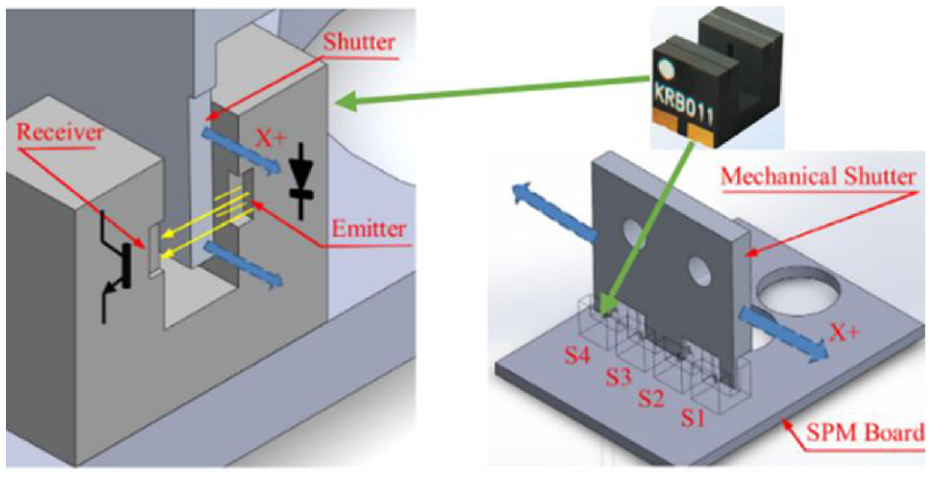
Slotted photomicrosensor array.
Sensor module design
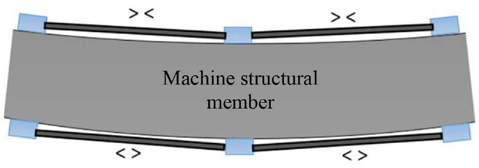
The first part of the new framework to consider was a method to convert strain of a structure to displacement of the sensor and create a practical sensor package for easy installation. Figure 2 shows a simple arrangement where four length changes can differentiate between elongation (thermal growth) or bending. Although two lengths on opposing sides could achieve this, additional lengths enable localised distortion to be more accurately detected as, the bending may not be uniform over the length of the structure being measured. The effect of that bend will also differ with distance from the bend source to where the effect of the bend is being realised which could be the tool or workpiece.
Simple framework for bend detection.
In order to follow the low-cost route, unidirectional CRFP rods were selected to bridge the gap between sensors. These have the additional important advantage of having a low CTE of 0.5 µm/m/°C (depending on the composition), a high longitudinal stiffness, low cost and they are very light weight.
Flexure system
Only a single degree of freedom is required in the sensor. Using a sliding guideway would be too complex and suffer from stiction with sub-micron movements. A rolling element guideway may not have stiction problems but would still be complex and potentially bulky to implement. Given the application, the sensor range is very small therefore a flexure system was deemed the most appropriate, providing simplicity and infinite resolution. The disadvantage is that such a flexure requires force to bend it which will result in compression losses in the connecting rods. The effect of this can be seen in the simulation and experimental results sections respectively.
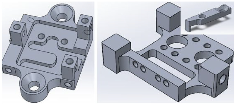
Figure 3 shows the main sensor module components. The left image is the static part which attaches to the machine structure and in which the circuit board with SPMs sits. There is a channel cut out for the wires to route and exit neatly. It has tapped holes in the top of each of the three vertical posts to secure a cover. The right image is the moving part which attaches using 0.5 mm thick spring steel (see Figure 6 for full assembly). Inset in Figure 3 is also one of the fingers, four of which attach to the moving part. The fingers have a tip we call a shutter which fits inside the SPM and provides the light interference. The section on sensor adjustment covers the logic for this solution.
Simple framework for bend detection.
Sensor simulation
The purpose of the design is to pass strain of the surface being measured into one-dimensional translation of the shutters relative to the photomicrosensors. FEA was used to validate the design. Figure 4 shows the flexures deformed and translation of the moving part. Using 1 N of force, the displacement is 0.39 µm therefore the stiffness is 2.5 N/µm. Variability across each shutter was less than 8 nm.
Deflection simulation for flexure design.
Sensor adjustment
The shutter was originally made from a single aluminium piece which was manually filed to match the spacing of the SPMs and give the best voltage range. This was a labour-intensive process therefore four separate shutters each with their own small adjustment was needed, hence the four fingers.
Another issue observed was the limited availability of the Kingbright KRB021 sensor. We moved to the Kingbright KRB011 which is slightly bigger at 4 mm wide compared to 3 mm, but is otherwise the same and is more widely available.
Using a flexure to control the shutter motion means that it has a resting position which will represent the middle of the measurement range (after adjustment). When installed on the machine, we require the sensor to be in that same resting position. To facilitate this, the connecting rods use a friction clamp that when loose, has plenty of movement to avoid adverse axial loading of the sensor. Figure 3 shows the end of the CFRP rod with two cuts which allows free movement of the insert (which connects to the sensor) until clamped. This clamping process did not induce any significant lateral movement affecting the readings on the bench test but when we installed on the machine vertically, we still had to apply some fine individual shutter adjustment (Figure 5).
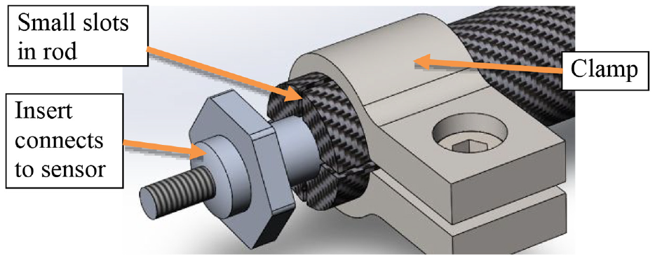
Connecting rod clamping to aid installation.
Prototype sensor bench results
Figure 6 (inset) shows the aluminium prototype without the cover (which attaches to the static part via the three threaded holes). The cover reduces ingress of dirt and light contamination. Figure 6 also shows a cylindrical structure on which the framework has been installed. There is a 450 mm separation between the sensor modules which are joined by 10 mm diameter unidirectional CFRP rods.
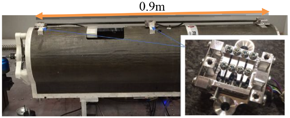
Prototype module and framework for bench test.
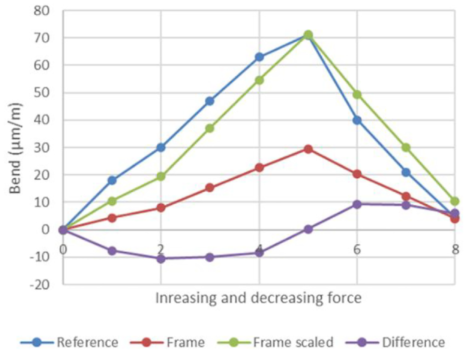
A static force was applied centrally, and the bend measured using a laser interferometer co-located on the structure. As expected, the flexure in sensor system causes compression/tension in the connecting rods requiring a scaling factor of 2.4 (60% loss) to be applied on top of the base sensitivity of the sensor which is 0.16 V/µm. 14 Figure 7 shows the result which has a residual non-linear error of ±10 µm/m after scaling the output. The sensor modules were not calibrated, so the existing linearity of the SPM output may be a contributing factor.
Simple framework for bend detection.
Error compensation result
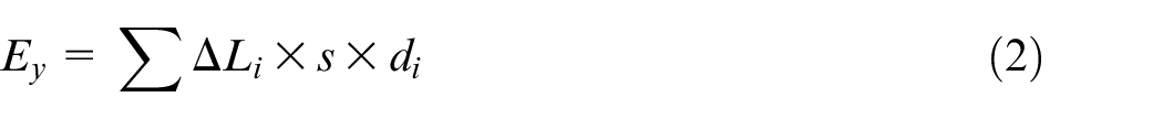
The four measured length changes needed to be converted to a bend effect at the tool. A simple model based on the differences between the front and rear framework sections and the distance to the tool was used to calculate the error in the Y axis direction
Where
Machine tool ram installation
The rectilinear frame was installed on the CFRP ram of a Fidia 3-axis CNC machine. Two lengths were installed between the two guideways at the rear of the ram and two at the front (the same way as the bench test). Figure 8 shows the setup on the machine. There was only a 50 mm gap between the column of the machine and the rear of the Z axis ram, but this was sufficient for the installation thanks to the compact size of the sensor. The machine has an integrated high-speed spindle which has a spindle chiller system.
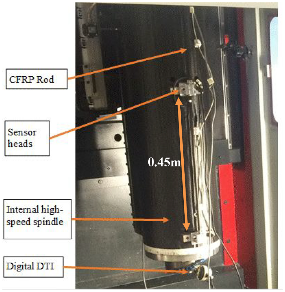
Framework installed on the machine ram (Z axis).
Referring back to equation (2), the separation s of the front and rear frames was 0.34 m once installed. The distance
The first test was passive that is, no compensation was being applied. The new measurement system and calculated error were recorded at the same time as the displacement of the tool in the Y direction. A digital dial test indicator (DTI) with serial communication was used for this. These are good quality displacement sensors with a 1 µm resolution and accuracy of 3 µm over the 12 mm measuring range. In hindsight, a higher resolution sensor would have been better once we learned the machine had such good cooling of the main spindle. The machine was located at a partner site and we had not tested it before. The quality of the spindle cooling systems is evident in the first result shown in Figure 9. Running the spindle at 16,500 rpm, there is an initial negative error followed by a positive error until the spindle was stopped after 50 min. Despite the small error, the model results followed the profile very well. The maximum difference was just 2 µm. The cyclic effect is the spindle chiller system turning on and off automatically. This causes small, but still measurable, fluctuations.
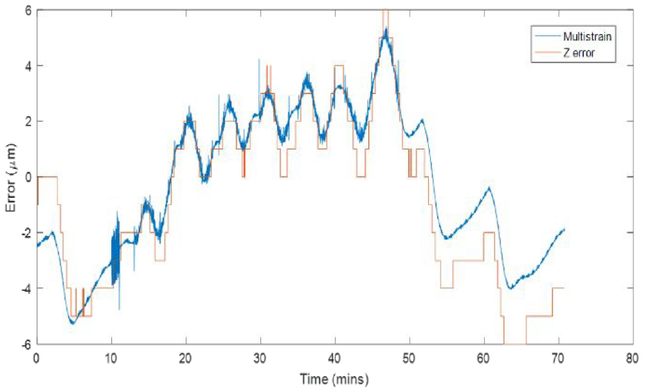
Comparison of model output to measured error.
Real time compensation result
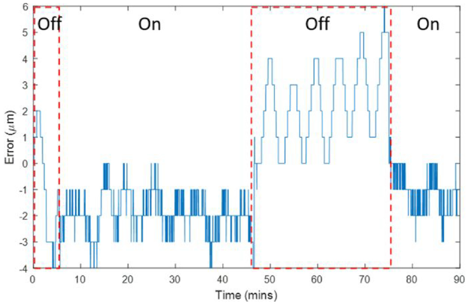
The machine tool uses a Fidia controller. It has proprietary compensation functionality for various machine errors, similar to many modern NC systems. The controller is Windows based and custom applications can be installed. Applications can access information such as axis positions and update various NC parameters including, offsets and compensation values. In collaboration with Fidia, a simple windows program was created to get the sensor data and calculate the error using equation (2). This method enabled real time compensation to be applied similar to other modern NC systems. The spindle was run continuously at a spindle speed of 16,500 rpm. The result, shown in Figure 10, starts with the compensation off for the first 5 min, then it was turned on for 40 min, off again for 30 min and finally turned on for the last part of the test. The data shows that the compensation holds the error within just 4 µm, reducing drift and the amplitude of the chiller cycle effect.
Compensation result for bend effect.
Conclusions
A new rectilinear framework has been created which incorporates a novel design of low cost, high sensitivity displacement sensor and CFRP connecting rods. The system has been applied on the ram (Z-axis) of a CNC machine tool and incorporates four strain measurements to calculate the effect of bending. Using a compensation feature in the Fidia controller, the calculated error was used to reduce thermal error between the tool and workpiece from 10 to 4 µm for a high speed spindle duty cycle. There was limited time on the machine so future work is needed to validate more cycles with higher resolution and compare bending with expansion. Non-linearity in the sensor for larger movements can be reduced with sensor calibration.
The aluminium sensor housing required a relatively costly amount of machining time therefore a new 3D printed alternative is under development (Presented at LAMDAMAP 2020). The target is <£50 per frame section. From our review, we believe this is the first time a non-fibre based rectilinear framework like this has been devised. Work on the arrangement of the transmissive photomicrosensors is prior art but this is the first time such sensors have been applied for practical displacement measurement, enabling high resolution strain sensing. The proposed solution is also an order of magnitude lower in cost but higher in sensitivity to FBG frameworks.
Footnotes
Acknowledgements
The authors gratefully acknowledge the UK’s Engineering and Physical Sciences Research Council (EPSRC) funding of the EPSRC Future Advanced Metrology Hub (Grant Ref: EP/P006930/1) and industrial partner Fidia SPA.
Declaration of conflicting interests
The author(s) declared no potential conflicts of interest with respect to the research, authorship, and/or publication of this article.
Funding
The author(s) received no financial support for the research, authorship, and/or publication of this article.