
Abstract
This article presents a new integrated geometric model that takes worktable as reference for five-axis machine tools. It could simplify the description of different machine kinetic structures and uniform the measurement coordinate system and machining coordinate system. Based on this model, a new method of measuring geometric errors with conventional instruments is proposed. It could break through some existing limitations, such as special instrument, specific machine kinetic structures, or errors incompletion. In addition, some deviation errors in measuring process could be eliminated to improve accuracy further. Finally, a series of experiments are conducted on a five-axis machine tool with rotary worktable and tilting head. The results show that the error model and measuring method are effective and applicable.
Introduction
Five-axis machine tools greatly facilitate the machining of complex parts. They provide five degrees of freedom between workpiece and tool, usually by three linear axes and two rotary ones. With the increasing of precision manufacturing demand, higher machining precision of five-axis machine tools is put forward. However, five-axis machine tools with rotary axis are more susceptible as they have more than 30 geometric errors. 1 The geometric errors cause deviation of tool position and orientation from the NC code values, which could affect the geometric accuracy of the machined surface. Therefore, the geometric error measurement is an essential issue for improving machining accuracy.
For linear axis, the geometric errors could be measured efficiently with some instruments and sophisticated theories.2–5 However, the errors in rotary axis are difficult to be measured, due to lack of accessibility.6,7 Many scholars proposed their own measuring methods to improve it. Lei and Hsu8,9 developed a spherical test with a special “3D probe-ball” and the least square estimation method to get some geometric errors of a specific five-axis machine tool and link errors of rotary axis. Tsutsumi and Saito 10 proposed a calibration method based on the simultaneous four-axis control technique for five-axis machine tool with tilting rotary worktable. It could identify eight deviations inherent to worktable at some specific planes. Mayer and Zargarbashi 11 developed a method to estimate the link errors through an iterative procedure based on an identification Jacobian matrix and special “Capball” instrument, which could estimate four tilt errors and center line offsets of a rotary axis. Zargarbashi and Mayer 12 proposed a method that could assess two radial and two tilt motion errors of rotary axis with ball-bar instrument, but it was confined to the rotation axis of worktable. Zhu et al. 13 proposed a method for identifying six errors of rotary axis with ball-bar instrument, but it was also limited to the rotation axis of worktable. Ibarakil 14 proposed a scheme to calibrate eight error motions at some specific measurement planes of a rotary/tilting table with the special “R-test device.” These methods have some similar utility limitations, such as special instrument, specific machine kinetic structures, errors incompletion, and so on. And how to eliminate the deviation errors in measuring process does not gain enough attention. Based on our knowledge, up to now, there is no standard measurement criterion for five-axis machine tools.
Besides the problems mentioned above, how to define the integrated geometric model (IGM) and the corresponding measurement coordinate system (MECS) is another problem. Many scholars6,7,12,13,15 used a multibody system (MBS) that took machine bed as reference to define IGM, and applied homogeneous transfer matrix (HTM) to describe it. However, the kinetic structures of different five-axis machine tools have various types. This could cause that the actual NC feed directions of worktable and tool relative to bed are opposite, and IGM might be contrary to MECS.
From the analyses, this article presents a new description of IGM that takes worktable as reference to uniform MECS and machining coordinate system (MCS). Based on it, a new method of measuring geometric errors for five-axis machine tools is proposed. It could resolve the above problems effectively.
This article is organized as follows: section “The new IGM for five-axis machine tools” provides the definition of error parameters and the IGM based on worktable for five-axis machine tools. Section “The new method of measuring geometric error for five-axis machine tools” discusses the proposed method of measuring geometric errors of both linear and rotary axes in detail. Some experiments and results are presented in section “Experiments and results,” and finally conclusions are drawn in section “Conclusion.”
The new IGM for five-axis machine tools
Definition of i-axis error model
It is known that any axis i has six degrees of freedom and corresponding errors in three-dimensional space. General geometric error model of i-axis is established based on 4 × 4 kinematics HTM. The composition of positional and orientational errors of i-axis could be described as equations (1) and (2), respectively, and the comprehensive geometric errors of i-axis could be described as equation (3)
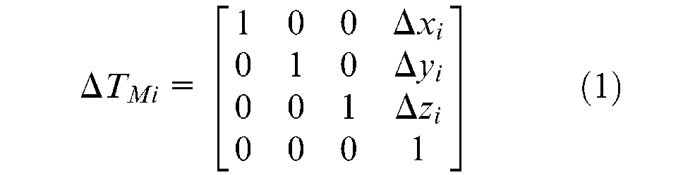
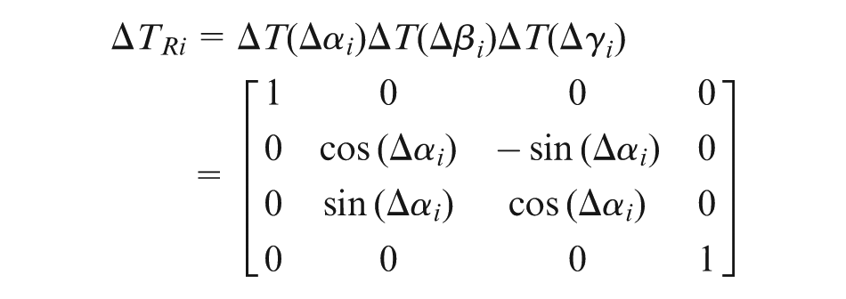
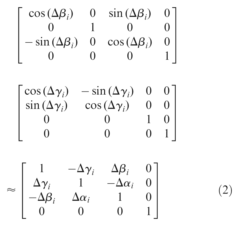
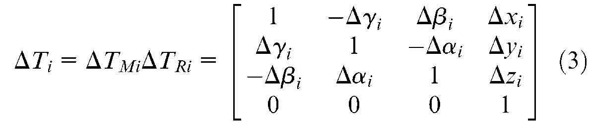
where ΔTMi, ΔTRi, and ΔTi are i-axis’s positional, orientational, and comprehensive geometric errors, respectively.
Definition of IGM based on worktable
Since a machine kinetic structure could be described by a MBS, the IGM of five-axis machine tools could also be defined by it. The reference of both MBS and IGM is usually defined as machine bed, which is the base of MECS. However, due to the fact that actual NC feed directions of worktable and tool relative to bed are opposite, the IGM might be contrary to MECS.
According to the MBS theory, a series of MBS based on different references could be established for an identical system. Taking worktable as reference for both MBS and MECS, all of feed motions could be defined as the movements of tool relative to worktable. So the IGM, MECS, and MCS could be uniformed.
Taking a five-axis machine tool of the CZFXYB kinetic structure as example, its compositions are shown in Figure 1. The MBS topology based on machine bed is shown in Figure 2, and the proposed MBS topology is shown in Figure 3.
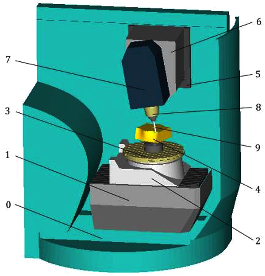
The composition of a CZFXYB five-axis machine tool. 0: bed, 1: Z-axis, 2: C-axis, 3: worktable, 4: workpiece, 5: X-axis, 6: Y-axis, 7: B-axis, 8: spindle, and 9: tool.
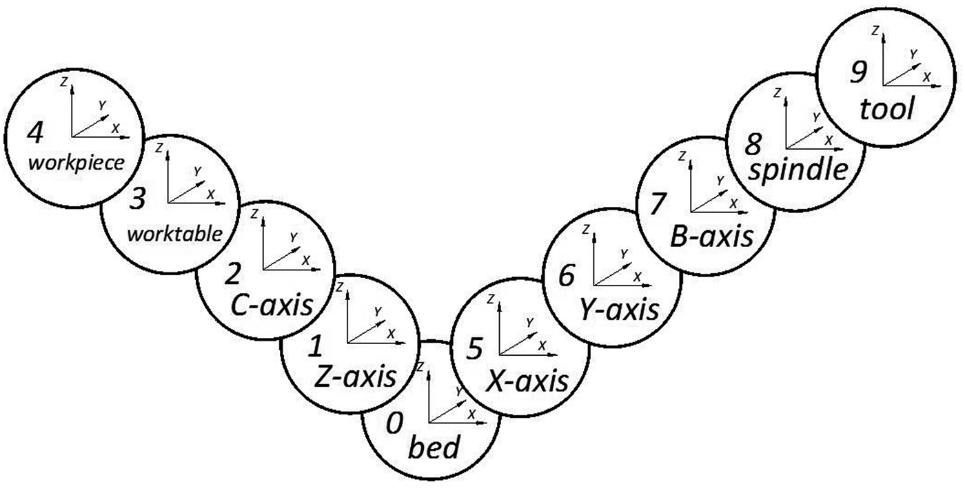
The MBS topology diagram based on machine bed.
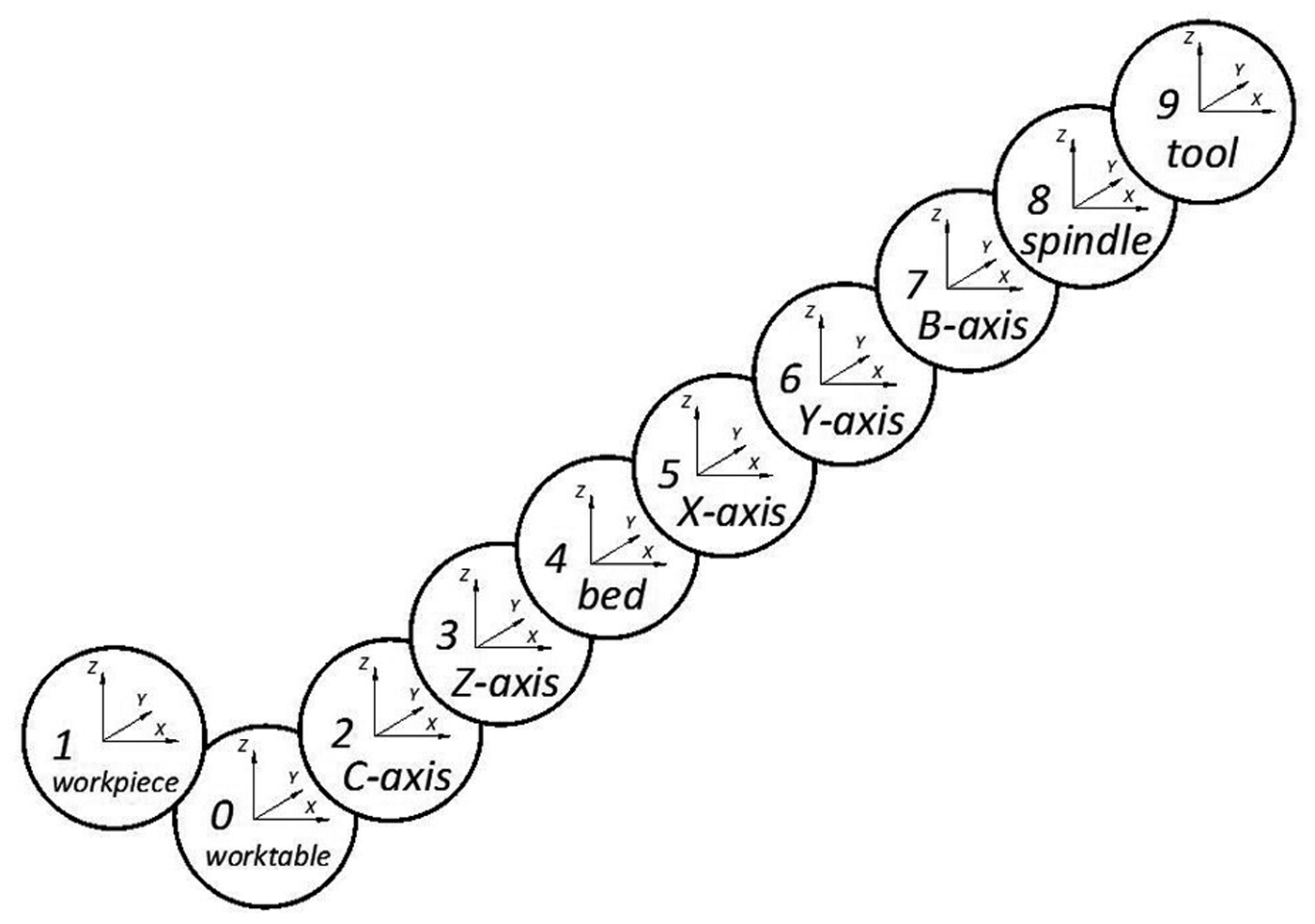
The MBS topology diagram based on worktable.
Moreover, the proposed MBS could combine two kinetic chains (bed to workpiece and bed to tool) into one (workpiece/worktable to tool). Hence, it could simplify the description of different machine kinetic structures. For example, the FCZXYB MBS could describe five types of five-axis machine tools, such as CFZXYB, CZFXYB, CZXFYB, CZXYFB, and CZXYBF kinetic structures.
The following is the derivation of IGM from the proposed MBS.
1. Ideal IGM. The ideal IGM of tool tip position Pideal and orientation Videal could be described as equation (4), which is based on the inverse kinematical transformation (IKT) theory as follows
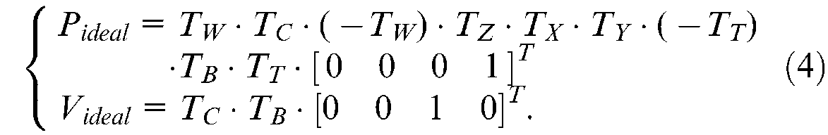
where TC, TZ, TX, TY, and TB are the ideal kinematical HTM about C, Z, X, Y, and B-axes. TW is the workpiece positional HTM about C-axis, and TT is the tool tip positional HTM about B-axis.
2. Actual IGM. Taking geometric errors into account, the actual IGM of the tool tip position Pactual and orientation Vactual could be described as equation (5) based on the IKT theory
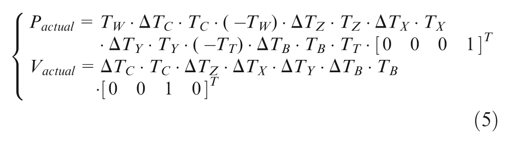
The new method of measuring geometric error for five-axis machine tools
The measuring method of linear axes
There are many works about the measurement of linear axes. The 10-line method 5 based on laser interferometer is selected for its applicability.
The 10 lines are the trajectories of point P fixed on the spindle and its positive offset points P′, P″, and P″′ that move with X, Y, and Z-axes relative to worktable, as shown in Figure 4. The positional errors of the 10 lines could be measured by laser interferometer directly, and the 21 geometric errors of X/Y/Z-axes could be identified by corresponding algorithms. 5
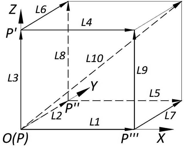
Ten-line measure diagram for linear axes.
If a measured axis is a lower sequence body of MBS, the offset point could be realized by the movement of other higher sequence bodies relative to worktable. Taking the CZFXYB kinetic structure as an example, the offset point P″ and P″′ for Z-axis could be realized by Y-axis and X-axis moves, respectively. If the measured axis is not a lower sequence body, such as Y-axis, the offset points could only be realized by some attachment fixed on the spindle.
The measuring method of rotary axis
Rotation Around Tool Center Point (RTCP) and Rotation Around Part Center Point (RPCP) are the basic functions of five-axis machine tools. When a function is active, NC system applies tool tip coordinates to control tool path. If the X/Y/Z coordinates in NC code have no change, the tool tip position would be fixed in ideal conditions no matter what the movement of rotary axis is. Using the functions, the positional errors of tool tip, when an axis rotates, could be measured to identify the geometric errors of rotary axis.
The method for the rotary axis of worktable
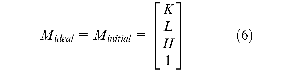
According to the new IGM, the kinetic structure, of which the worktable is mounted on rotary axis, needs to be treated as that all axes or bodies rotate around the worktable. Taking the CZFXYB kinetic structure as an example, the MECS origin O is the intersection of the worktable surface and C-axis, as shown in Figure 5. Set point N fixed on the worktable as measuring base, and point M fixed on the axis of spindle as measuring point of which initial coordinates are (K, L, and H) in MECS. When C-axis rotates and RPCP is active, the ideal coordinates of M in MECS are always as following
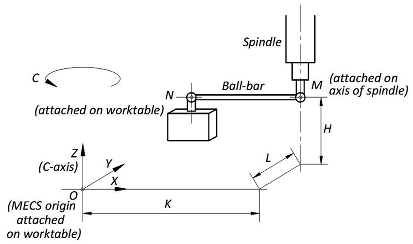
Measure diagram for C-axis.
and the actual coordinates of M are
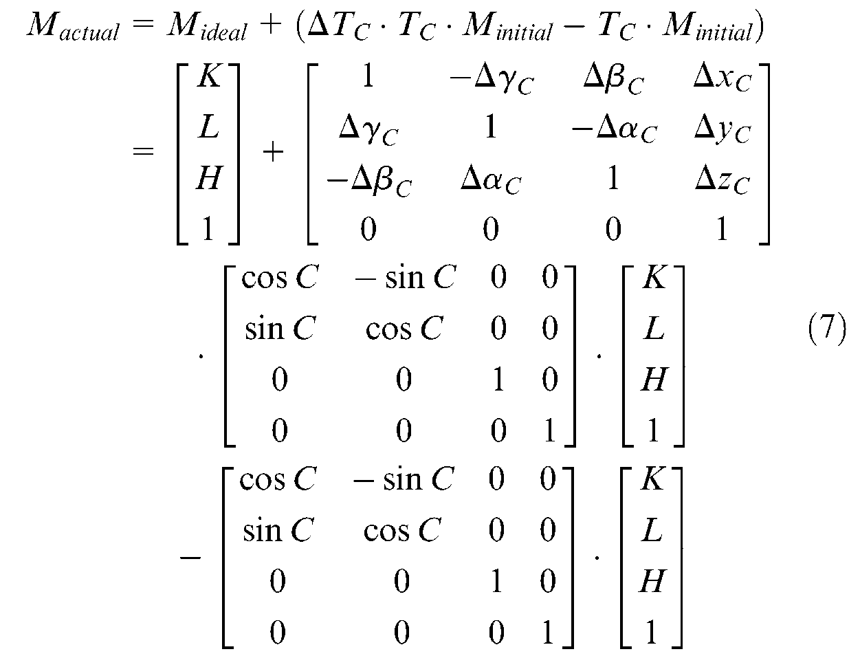
So the positional errors of M are
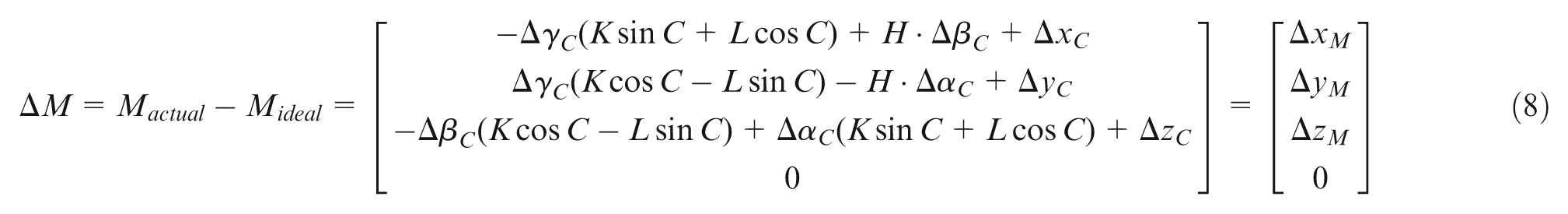
A ball-bar instrument is used to measure the distance error between N and M when C-axis rotates. By adjusting the position of N, ball-bar could parallel to X/Y/Z-axes, respectively. Under ideal conditions, the relative position of N and M and the distance |NM| should remain the same. If the distance changes, the positional errors ΔxM, ΔyM, and ΔzM could be measured by a ball-bar system directly.
Three groups of ΔM could be measured from different (K, L, H) combinations. Taking above parameters to equation (8), the six geometric errors of C-axis could be identified.
During the measuring process, the deviation errors are inevitable. The following points are the proposed eliminative ways:
1. Eliminating geometric errors of linear axes. The linear axes might introduce geometric errors to ΔM. Their relative positions (SX, SY, and SZ) in machine coordinate system could be obtained by equation (9) based on the IKT theory
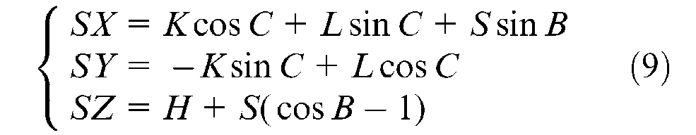
where S is the distance between M and B-axis. Because the identified errors are based on MCS, the geometric errors of linear axes could be eliminated from ΔM directly.
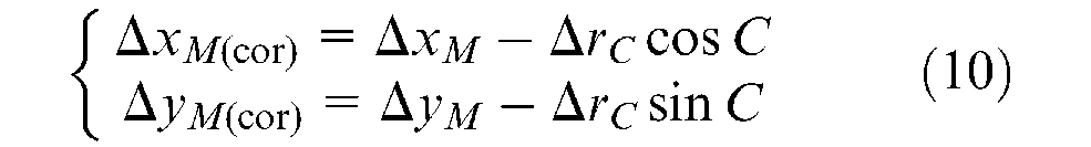
2. Eliminating radial runout error of M. The position of M is controlled by arbor installation. Under ideal conditions, M is fixed on the axis of spindle, but the actual installation might have a deviation. When measuring ΔxM and ΔyM, the ball-bar rotates around M relative to the XY plane. Therefore, a radial runout error ΔrC of M at C angle is introduced inevitably. It could be measured with ball-bar or dial indicator by rotating the spindle, as shown in Figure 6. Therefore, it could be eliminated by equation (10)
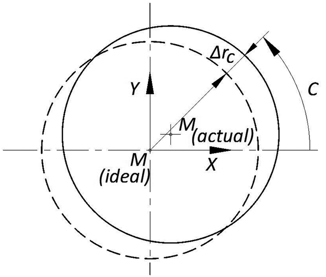
Radial runout error diagram of M relative to the XY plane for worktable.
The method for the rotary axis of spindle
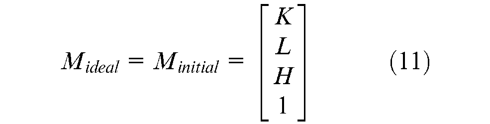
It is similar to the above. Taking the CZFXYB kinetic structure as an example, set the MECS origin O fixed on worktable as measuring base, and point M fixed on the axis of spindle as measuring point of which initial coordinates are (K, L, H) in MECS, as shown in Figure 7.
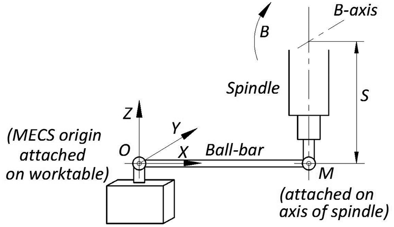
Measure diagram for B-axis.
When B-axis rotates and RTCP is active, the ideal coordinates of M in MECS are always as following
and actual coordinates of M are
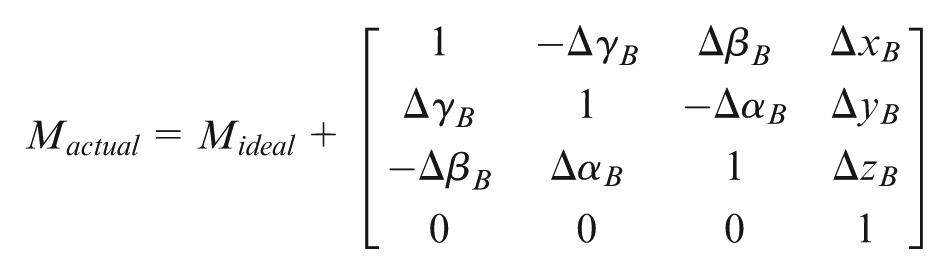
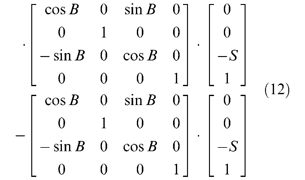
So the positional errors of M are
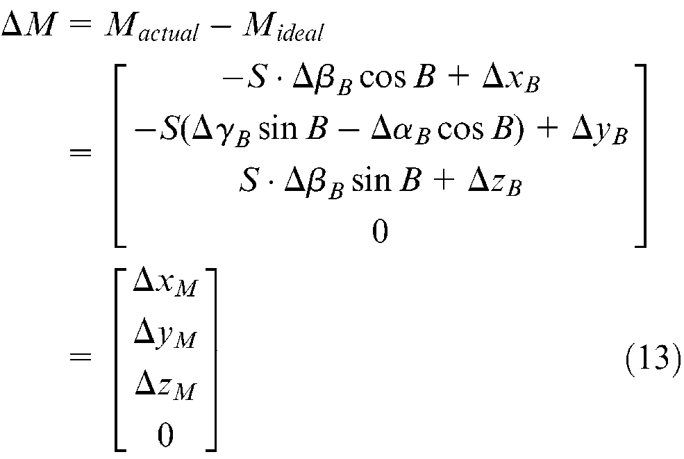
A ball-bar instrument is used to measure the distance error between O and M when the B-axis rotates. By adjusting the position of M, ball-bar could parallel to X/Y/Z-axes, respectively. Under ideal conditions, the relative position of O and M, and the distance |OM| should remain the same. If the distance changes, the positional errors ΔxM, ΔyM, and ΔzM could be measured by ball-bar system directly.
In addition, ΔyM could be characterized by some parameters, as shown in Figure 8. The relationship of them could be described as equation (14).
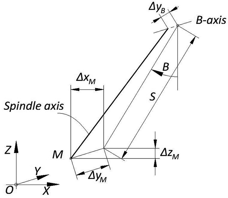
Geometric diagram of ΔyM.
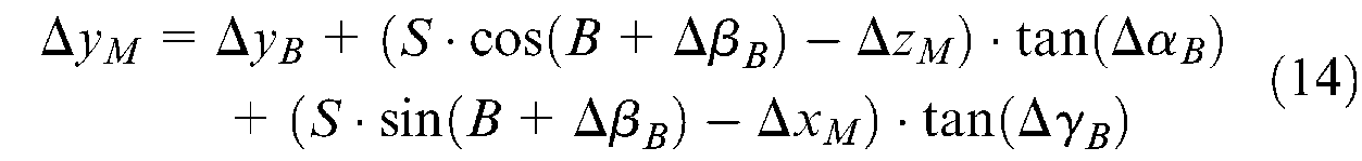
The three groups of ΔM could be measured from different S parameters. Taking above parameters into equations (13) and (14), the six geometric errors of B-axis could be identified.
The following points are proposed to eliminate deviation errors.
Eliminating geometric errors of linear axes. The way is the same as before.
Eliminating the radial runout error of M. The position of M is controlled by arbor installation. Under ideal conditions, M is fixed on the axis of spindle. By taking an installation deviation into account, when measuring ΔxM and ΔzM, the ball-bar rotates around M relative to the XZ plane. Therefore, a radial runout error ΔrB of M at B angle is introduced inevitably. When ball-bar parallels to X-axis, a radial runout error Δr0 in +X direction could be measured when spindle rotates from 0° to 90°, as shown in Figure 9, and the deviation error |WV| could be eliminated by equation (15).
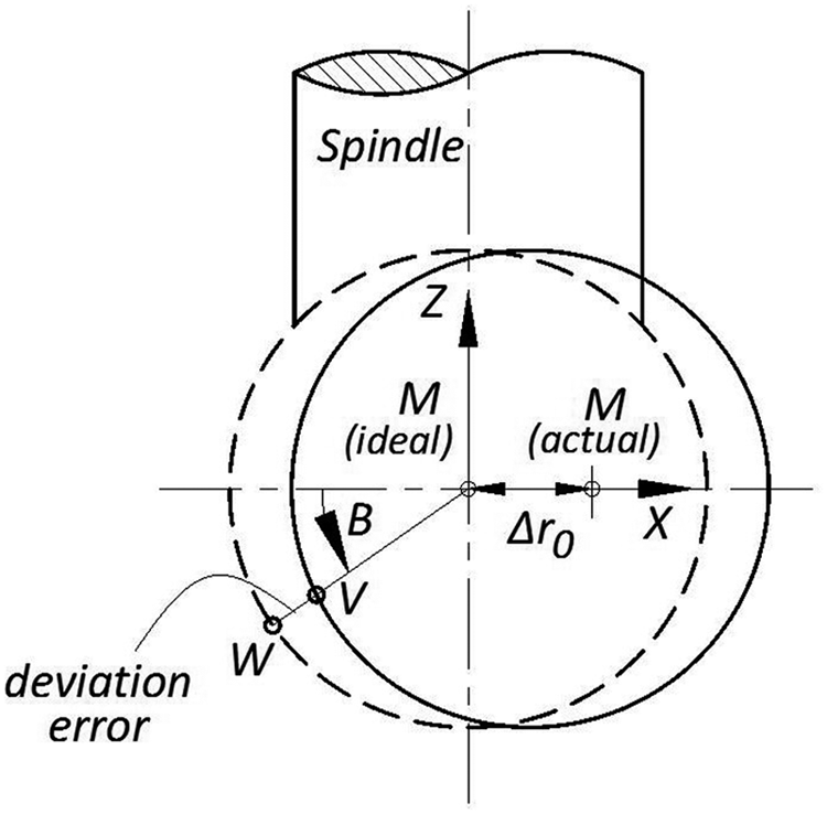
Radial runout error diagram of M relative to the XZ plane for spindle.
Experiments and results
To verify the validity of proposed IGM and the measuring method, a series of experiments were conducted on a DMU 100 monoBLOCK five-axis machine tool with the CZFXYB kinetic structure. The IGM and MECS were based on the worktable mounted on C-axis, and the instruments were Renishaw XL-30 laser interferometer and QC10 ball-bar system.
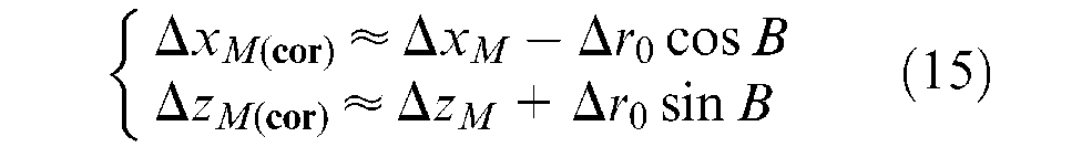
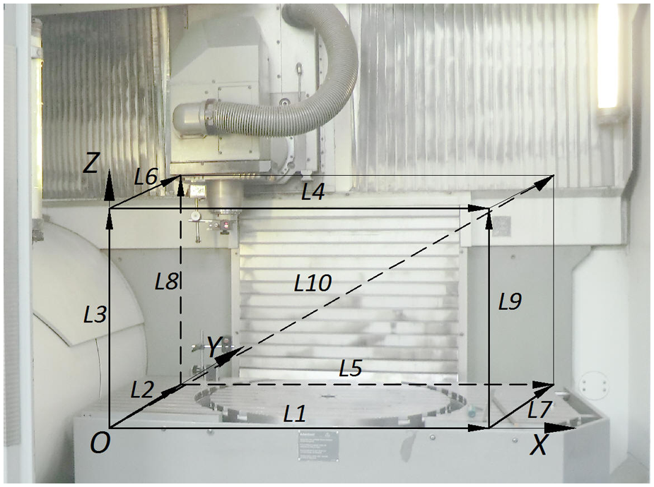
For linear axis measurement, the MECS origin was set to the minimum point of measuring volume that was from (100, −650, −500) to (900, −50, −100) in the machine coordinate system, as shown in Figure 10. The measuring point of 10 lines was the center of laser reflector mounted on the spindle. Each trajectory was divided into 40 equal divisions, and the laser interferometer could measure the positional errors of the discrete points automatically. The errors of other points could be calculated by interpolation. Figure 11 shows L1, L4, L5 measure scenes for X-axis.
The measuring volume in machine coordinate system.
The measure scenes of X-axis: (a) L1, (b) L4, and (c) L5.
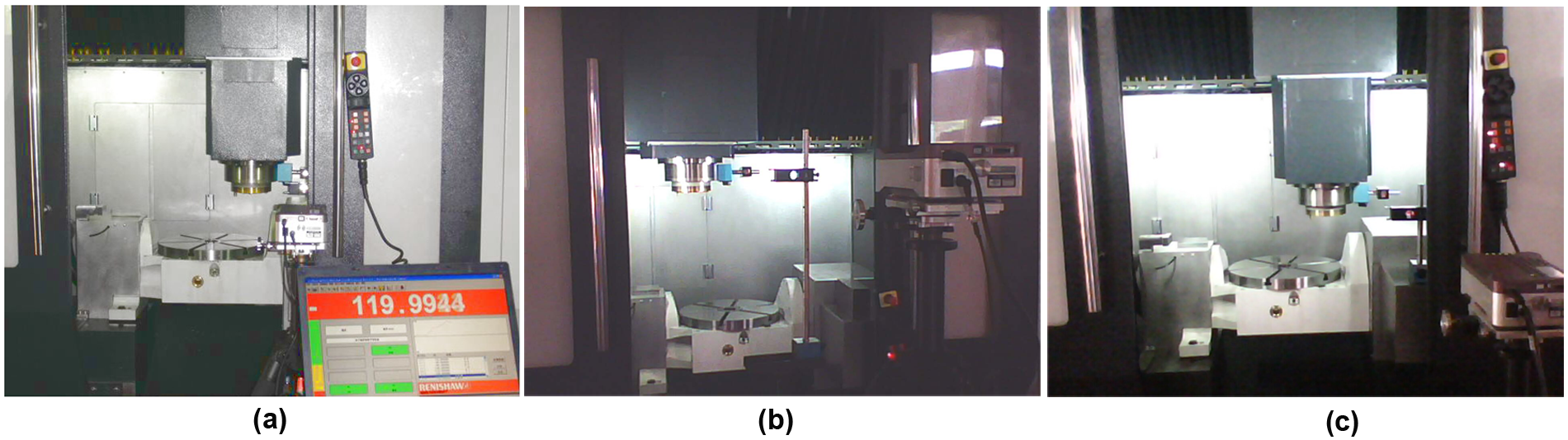
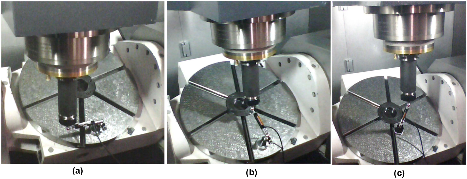
For C-axis measurement, different K, L, and H parameter combinations were (200, 152, 57), (310, 152, 57), and (310, 210, 452), which were realized by fixture mounted on worktable, as shown in Figure 12. The rotary range was 0°–360°, which was divided into 60 equal divisions. For B-axis measurement, different S parameters were 415.8417, 588.1654, and 472.4698, which were realized by different sized bars clamped on the arbor. The rotary range was 0° to −90°, which was divided into 45 equal divisions, as shown in Figure 13. The ball-bar system could measure ΔM of each discrete angle automatically. The errors of other angles could be calculated by interpolation.
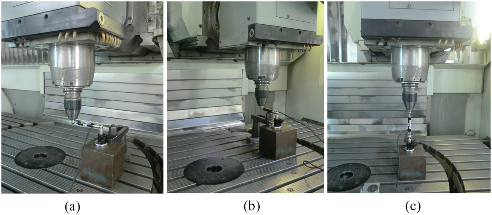
The measure scenes of C-axis: (a) ΔxM, (b) ΔyM, and (c) ΔzM.
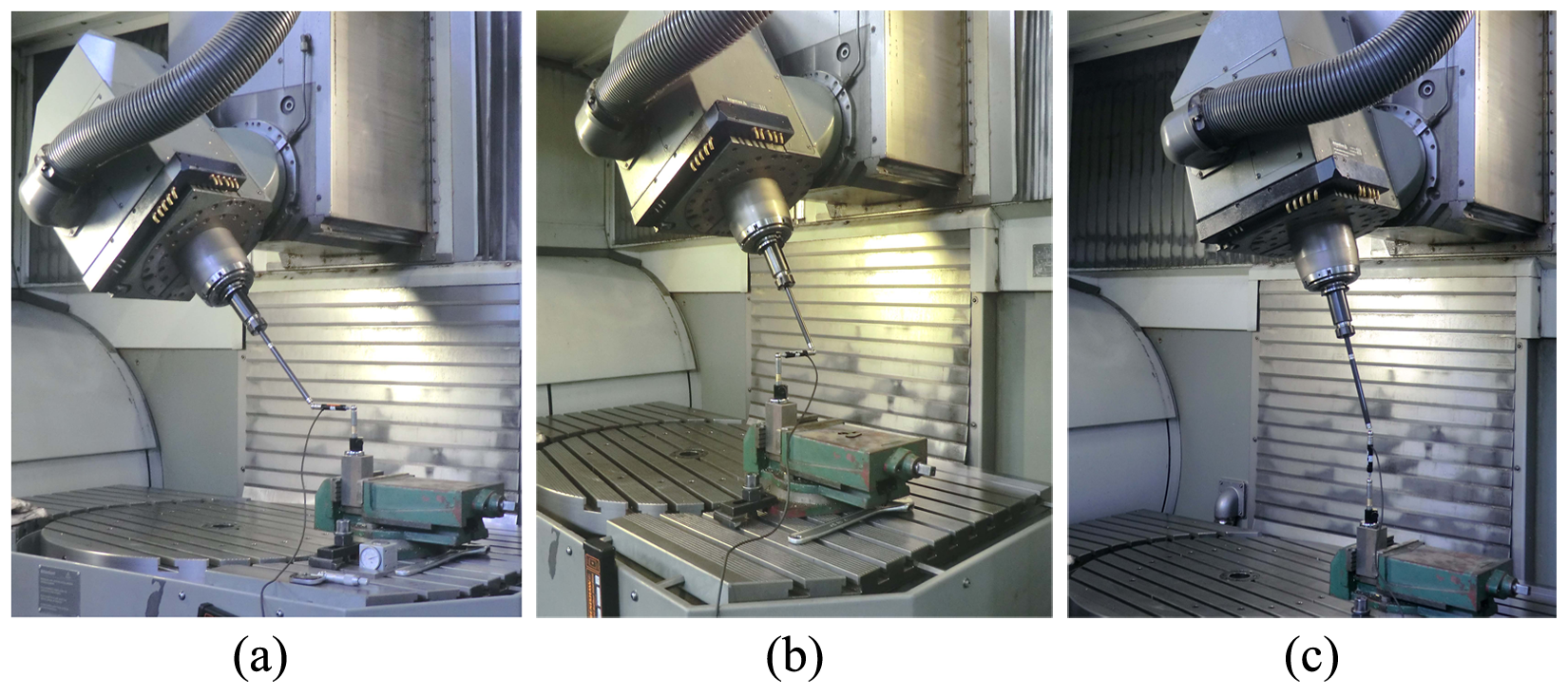
The measure scenes of B-axis: (a) ΔxM, (b) ΔyM, and (c) ΔzM.
To improve the measurement stability, the process began after the machine had run for at least 1 h. All data were measured four times in a single direction. It could reduce the uncertainty caused by machine thermal deformation, lubricating inadequacy, moving clearance, and so on. Also, the measurements were compensated automatically for the change of environmental temperature and atmospheric pressure. The identified geometric errors of C/B-axes are shown in Figures 14 and 15, respectively.
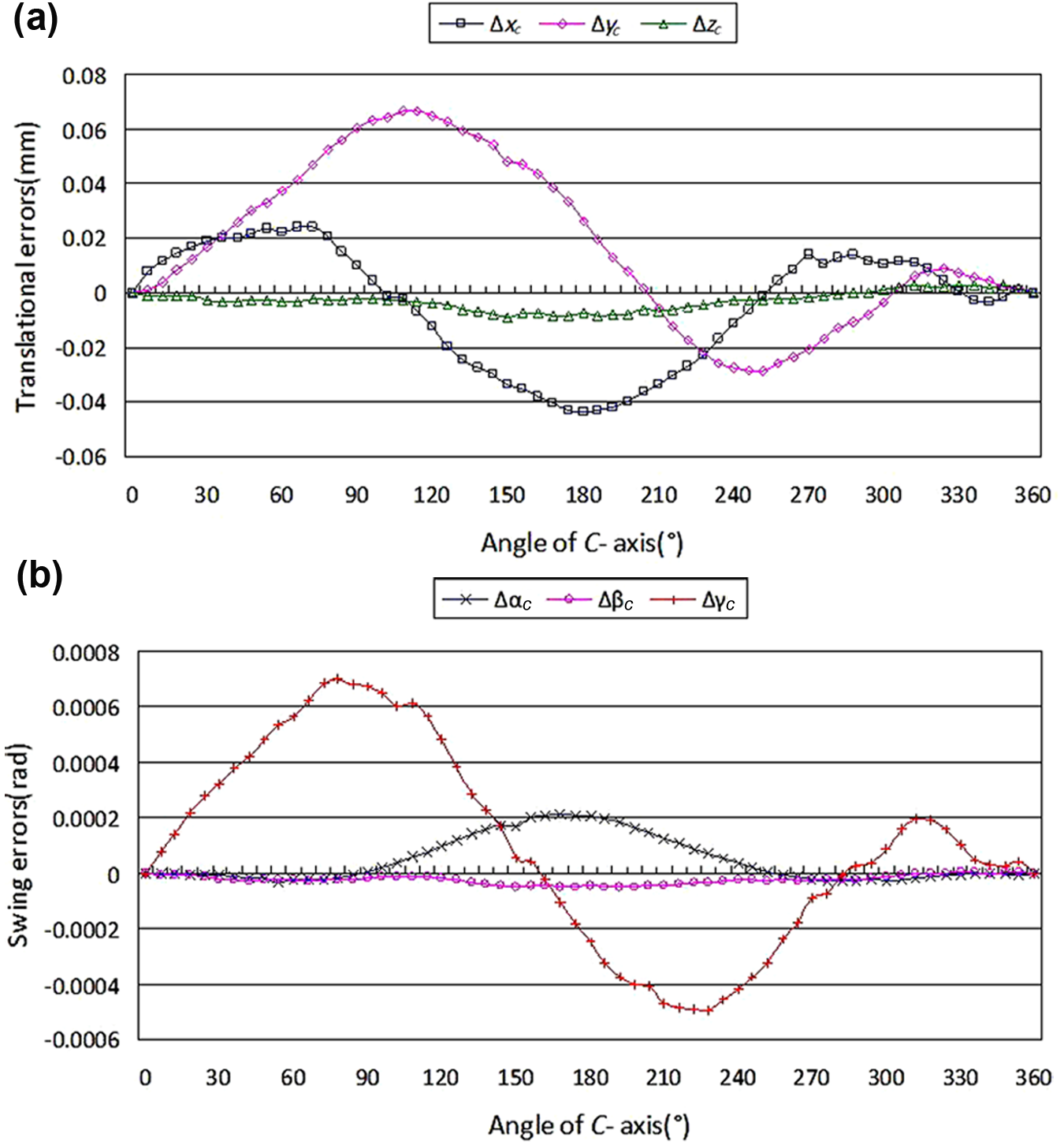
The identified geometric errors of C-axis: (a) translational errors of C-axis and (b) swing errors of C-axis.
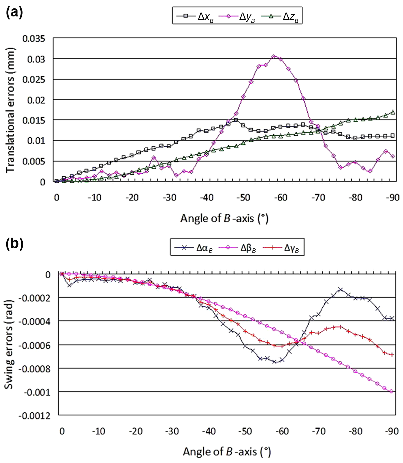
The identified geometric errors of B-axis: (a) translational errors of B-axis and (b) swing errors of B-axis.
Two same type specimens were machined. One was machined with the original NC program and the other was machined with its modified NC program for compensating geometric errors. After the specimens were machined, 120 discrete points that distributed uniformly in four toolpaths of different Z layers were chosen to be measured by a coordinate measuring machine (CMM). When the specimens were dimensionally measured by the CMM, the measure base was defined as design model base. We applied the contour errors to compare the design profile and the measured profile and did not use a curve to fit the measurement points. Figure 16 shows the model, machining, and measure scenes of a specimen. Through the comparison between the discrete point coordinates of design model and actual specimens one by one, the contour errors of the 120 points could be obtained, as shown in Figure 17. The average contour errors were reduced from 0.041 to 0.023 mm, and the maximum was reduced from 0.072 to 0.052 mm. Therefore, the machining precision could be increased effectively.
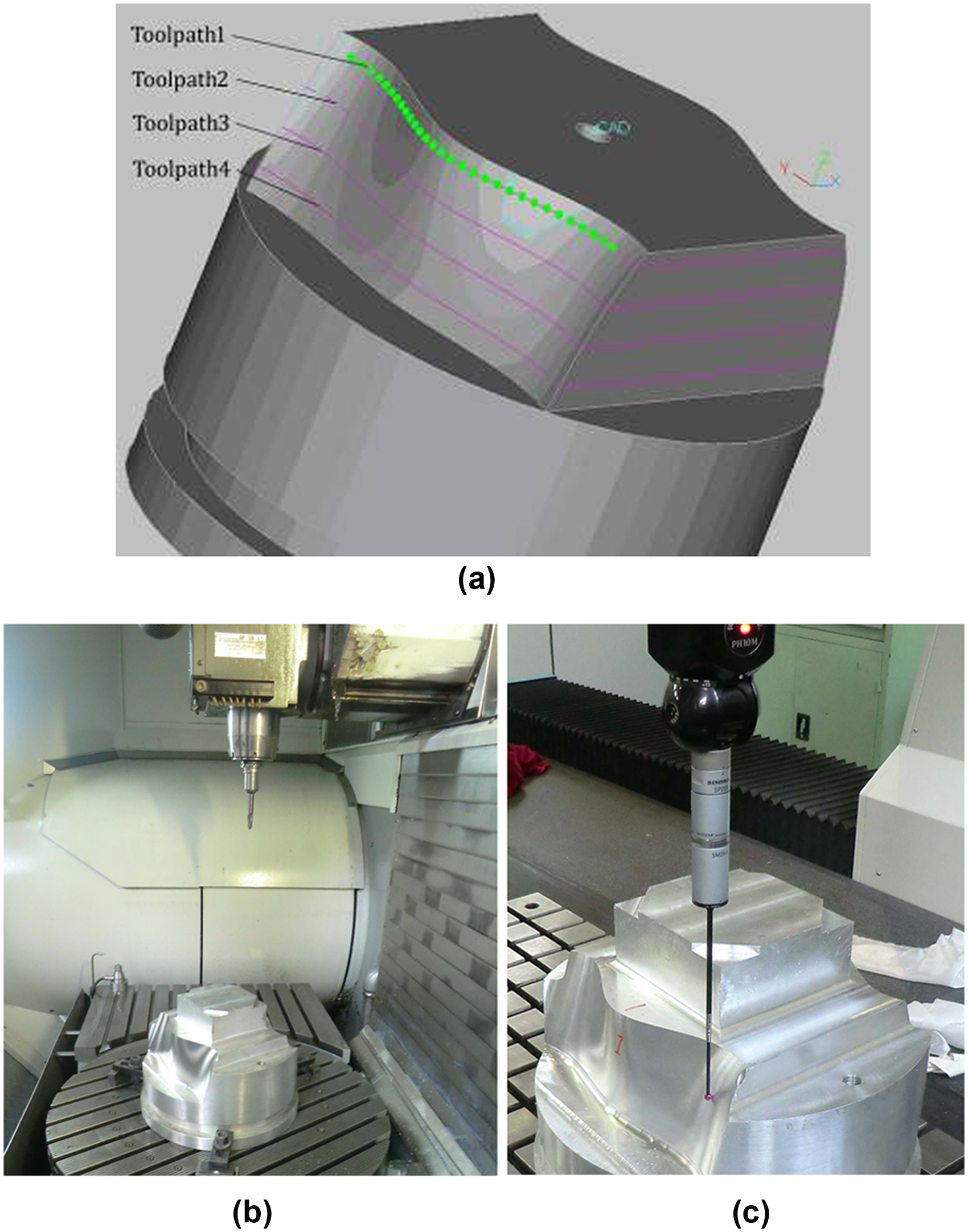
The scenes of machining and measuring a specimen: (a) 3D model, (b) in machining, and (c) in measuring.
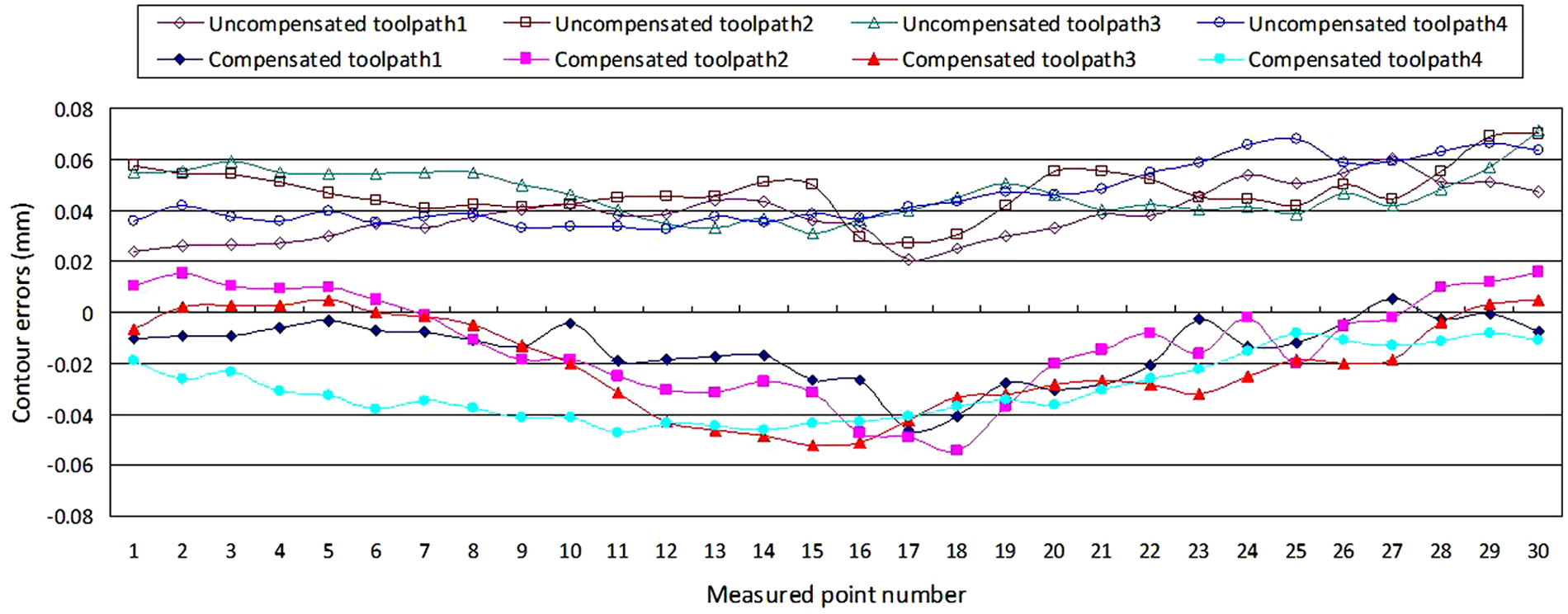
The contour errors comparison of measured points.
The proposed model and method have also been successfully applied to other experiments, such as a VMC-650M five-axis machine tool with the CAFYXZ structure for machining a turbine impeller part. Figures 18 and 19 show some measure scenes, and Figure 20 shows the distribution of contour errors measured by a CMM. As a result, the average contour errors were reduced from 0.0555 to 0.0370 mm, and the improvement of machining precision is clearly observed.
The measure scenes of Y-axis: (a) L2, (b) L6, and (c) L7.
The measure scenes of A-axis of worktable: (a) ΔxM, (b) ΔyM, and (c) ΔzM.
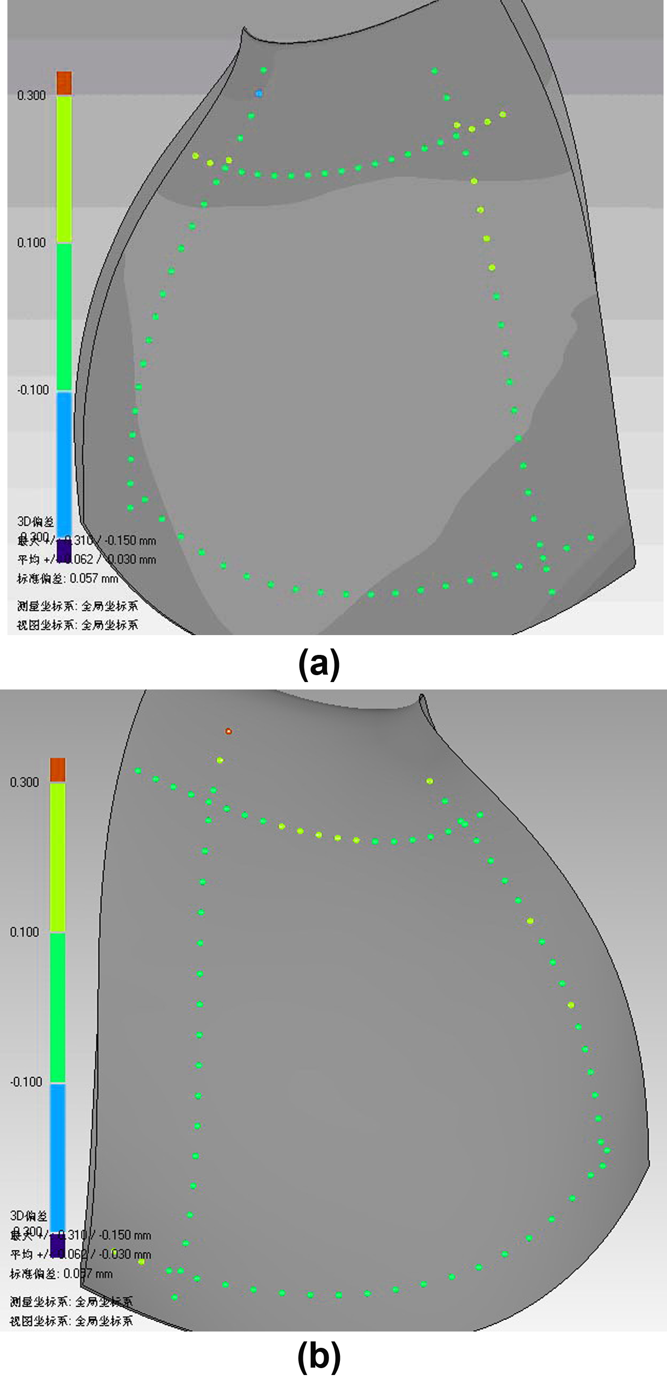
The distribution of contour errors (measured by CMM): (a) front face and (b) back face.
Conclusion
This article presents an MBS-based IGM, which takes worktable as reference for the five-axis machine tools. It could simplify the machine description of different kinetic structures and also uniform MECS and MCS.
Furthermore, a new method of measuring geometric errors with conventional instruments is proposed for the five-axis machine tools, including the measurement for rotary axes of worktable and spindle. It is suitable for any general type of five-axis machine tools, and no special instruments are needed besides laser interferometer and ball-bar system. It could identify 33 geometric errors efficiently, such as 21 linear axis errors and 12 rotary axis errors. In addition, the method eliminates some deviations caused by linear axis errors and ball-bar radial runout errors to improve measuring accuracy further. The process is similar to machining and is easy to implement. All the identified geometric errors are based on the MCS and could be applied directly to NC program compensation.
Finally, a series of experiments showed that the proposed IGM and measuring method are effective and applicable. From the contour errors comparison of specimens, the machining precision could be increased effectively.
Footnotes
Appendix 1
Funding
This work is supported by the Special Fund of High-end CNC Machine Tools and Basic Manufacturing Equipment (2010ZX04015-011), China. It is also supported by the Fundamental Research Funds for the Central Universities under Grant SWJTU 09ZT06 and SWJTU11CX144, and New Century Excellence Plan Grand NCET-09-0665.