
Abstract
This paper presents a novel kinematic modeling and error parameter identification method for a six-axis gantry automated fiber placement (AFP) machine. Multi-body system theory is used to model the kinematics of the AFP machine, and then use the homogeneous transformation matrix to represent the transfer relationship of the coordinate system. Based on 54 geometric errors of the AFP machine, a volumetric error transfer model is established. To eliminate the training bias caused by sampling randomness, 10-fold cross-validation combined with the Levenberg–Marquardt method is used to train the kinematic model of the AFP machine. Based on the coordinates of random points in space measured by a laser tracker, all the position-dependent geometric errors and position-independent geometric errors of the linear and rotary axes can be identified simultaneously. After the error parameters are identified, the average error of the random points in the X-direction is reduced from 0.72 to 0.08 mm, a drop of 88.9%. Corresponding experiments are carried out on the body diagonals and the winglet placement path. The experimental results show that the volumetric error transfer model and error parameter identification method proposed in the article can accurately predict the volumetric errors of the AFP machine, and can also meet the requirements of the AFP machine placement accuracy.
Keywords
Introduction
Fiber-reinforced composite materials have the advantages of low density, high strength and modulus, and fatigue resistance, which are widely used in the aerospace field. With the more and more extensive application of composite materials, automated fiber placement (AFP) technology has also developed rapidly. 1 The AFP combines the fiber conveying in the automated fiber winding and the prepreg cutting, laying, and refeeding in the automated tape laying, it can realize continuous variable-angle laying, and has higher adaptability. 2 AFP has become a typical process for the manufacture of large and complex aerospace composite materials, such as wing skin, fuselage panel, and wing spar.
With the increasing size of the aircraft structure, the placement speed of the AFP machine is also increasing, which places higher requirements on the placement accuracy. The placement accuracy of the AFP machine directly affects the forming quality of the parts. According to the different types, the errors of a machine tool can be divided into quasi-static errors and dynamic errors. Quasi-static errors mainly include geometric errors, errors caused by cutting force and thermal errors, accounting for more than 70% of the total errors of the machine tool. The dynamic errors are mainly the following errors of the servo system and the interpolation approximation errors. Therefore, the improvement of the machining accuracy of the machine tool is to reduce the quasi-static errors as the primary goal. Due to the particularity of resin-based composite materials, the AFP machine needs to be installed in a clean-room with constant temperature and humidity to ensure the molding quality of composite components. The end-effector elastic pressure roller (EPR) of the AFP head is different from the tool of a common CNC machine tool. The EPR does not need to participate in cutting parts, but only needs to provide a constant pressing force to compact the prepreg tow on the surface of the laying mold. To comprehensively evaluate the processing performance of the AFP machine, and improve the placement accuracy. After comprehensive consideration, this paper takes the modeling, measurement and identification of the geometric errors of the AFP machine as the main research objective, and provides a reference for the subsequent error compensation work.
The geometric errors of the linear axis of the CNC machine tool are mainly measured by a laser interferometer,3,4 but the whole process is relatively time-consuming. Although Liu et al. 3 realized that the six geometric errors of the linear axis can be obtained in one measurement, the assembly and debugging of the mirror group were difficult. The geometric errors of the rotating axis are mainly measured and identified by Double Ball-Bar (DBB) and R-test,5–7 but these methods need to decouple the measurement results to obtain the corresponding geometric errors, the measurement efficiency is not high, and it is impossible to identify all geometric errors of the machine tool simultaneously.
The use of traditional geometric error measurement and identification methods based on laser interferometer and DBB will lead to longer measurement times, which will lead to larger measurement errors. Therefore, a method that can quickly and accurately measure and identify the geometric errors of large machine tools is needed. Laser tracker has been widely used in the field of aircraft assembly. 8 Because industrial robots have lower accuracy requirements relative to machine tools, laser tracker is widely used in robot kinematics parameter calibration and error compensation. Tian et al.9–12 proposed an error compensation method based on error similarity, which successfully improved the positioning accuracy of industrial robots to within 0.4 mm. However, due to the low measurement accuracy of laser tracker relative to laser interferometer and DBB, the application in machine tools is mainly focused on the multilateration method. Aguado et al.13–15 studied the influence of the measurement noise of the laser tracker on the multilateration method, and measured and identified the errors of the machine tool. Although the multilateration method can improve the measurement accuracy of the laser tracker, the corresponding measurement workload will also increase exponentially, and the advantage of the laser tracker’s fast measurement speed is not fully reflected. Rudberg 16 optimized the kinematic parameters of the horizontal AFP machine and successfully improved the geometric accuracy of the machine tool, but the error measurement process was more cumbersome and required more points to be measured. Due to the existence of the EPR at the end of the AFP head, the influence of geometric errors on the laying parts of the AFP machine has no great influence on the CNC machine tool. In a clean-room with constant temperature and humidity, the influence of temperature and humidity on the measurement uncertainty of the laser tracker can be minimized. The laser tracker can directly measure the position information of the tool center point (TCP) of the AFP machine, which can directly reflect the influence of various geometric errors on the position error of the TCP. Choosing the ordinary measurement method of laser tracker can not only ensure measurement accuracy, but also greatly improve measurement efficiency.
Before error identification, it is necessary to analyze and model the various geometric errors of the AFP machine. The geometric errors can be divided into position-dependent geometric errors (PDGEs) and position-independent geometric errors (PIGEs), PDGEs are mainly caused by the manufacturing defects of the transmission components of the motion axis, and their values are related to the position of the guide rail. To improve the efficiency of error identification and realize the identification of all geometric errors simultaneously, it is necessary to fit the PDGEs of each axis and embed the calculation of regression coefficients into the error identification algorithm. PIGEs are mainly caused by assembly defects of machine tools, and their values are constant. Common machine tool kinematics modeling methods include Denavit–Hartenberg (D-H) notations, 17 multi-body system (MBS) theory,18,19 and screw theory.20,21 The D-H model based on homogeneous transfer matrix (HTM) is widely used in robot kinematics modeling, but D-H parameters are not easy to identify directly. Because the AFP machine needs six-axis linkage to complete the laying of complex profiles, the corresponding kinematic modeling and error analysis is more complicated than the common machine tool. MBS assumes that each part of the mechanical system is a rigid body, which can fully describe the geometric errors of the machine tool, and the errors of each axis are complete, which makes the kinematic modeling of the AFP machine standardized.
According to the established error transfer model and the TCP measurement data, the error parameter identification target function can be obtained. By selecting the appropriate optimization algorithm, the geometric error parameters of the AFP machine can be obtained. The Levenberg–Marquardt (L-M) method combines the advantages of the Newton method and the Gradient method, and can effectively deal with redundant parameters. By introducing a damping factor to adjust the characteristics of the algorithm, the optimal solution of the required parameters can be quickly obtained.
Literature22–24 based on the robot kinematics calibration method, carried out the kinematic parameter identification of different machine tools. Although the geometric accuracy of the machine tool can be improved, the errors can only be compensated by changing the NC codes. The error identification method based on laser tracker measurement data proposed in this paper integrates error fitting and 10-fold cross-validation into the error parameter identification algorithm. Not only can make full use of the data measured by the laser tracker, but also can simultaneously identify 54 PDGEs and PIGEs of all axes of the AFP machine. It greatly improves the measurement and identification efficiency of geometric errors, can greatly shorten the assembly and delivery time of the AFP machine, and can improve the competitiveness of the enterprise in the industry. For the identified geometric errors, the errors can be compensated by changing the NC codes, or using the error compensation table to compensate the errors, or using other error compensation methods.
This article presents the modeling, measurement and identification method for the volumetric errors of the six-axis gantry AFP machine. Its structure is as follows: Section 2 establishes a volumetric error transfer model based on MBS theory; the measurement method of geometric errors is described in Section 3; Section 4 introduces the identification method of error parameters; Section 5 analyzes the error parameter identification results; The identified volumetric error transfer model is experimentally verified in Section 6; The article is concluded in Section 7.
Kinematic modeling
Automated fiber placement machine structure
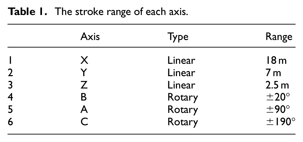
According to the size and shape of the laying parts, the AFP machine can be divided into gantry AFP machine, horizontal AFP machine, and robotic AFP. Among them, the gantry AFP machine is suitable for laying large and complex open curved surfaces, which is widely used. The 16 tows gantry AFP machine independently developed by Zhejiang University is a typical six-axis high-speed special machine tool, as shown in Figure 1. Table 1 lists the stroke range of each axis. The B-axis is connected to the end of the Z-axis, the B-axis, A-axis and C-axis intersect at a point, and the AFP head is installed on the flange at the end of the C-axis. The AFP head adopts the integrated structure of the creel house, which can effectively shorten the transmission distance of the tow and reduce the problems of tow jumping off redirects, tow twists and other problems caused by the long-pass fiber. 25
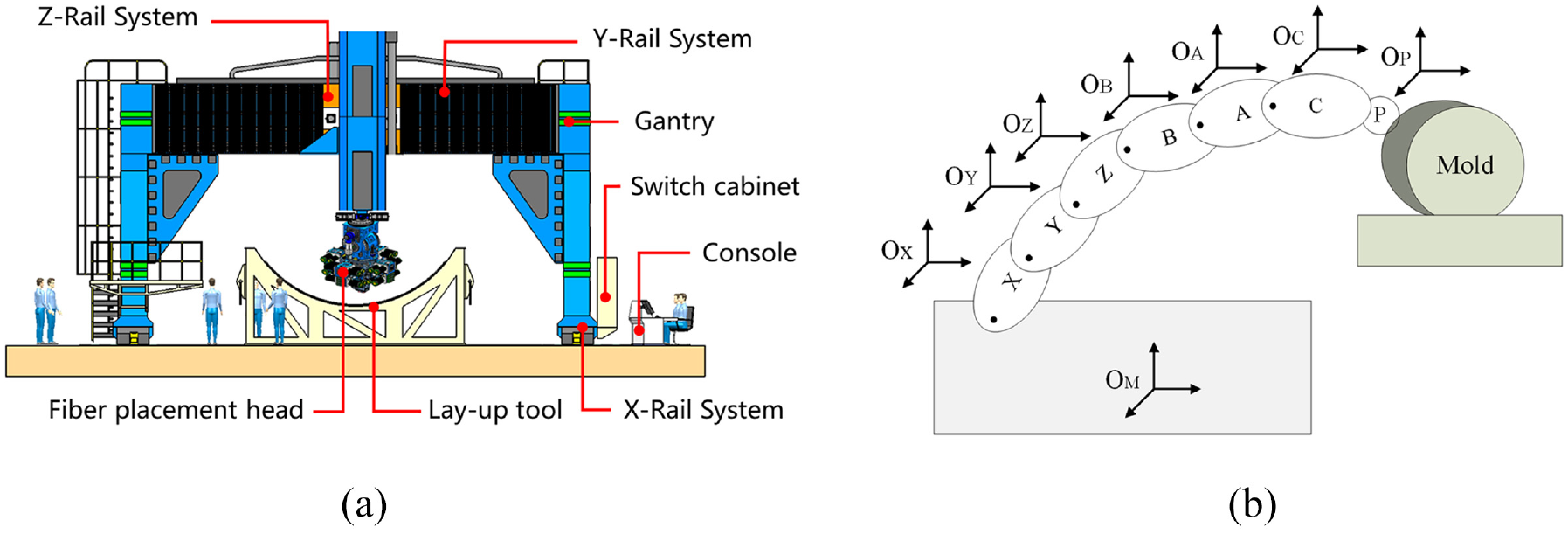
Sixteen tows gantry AFP machine: (a) Structure of the AFP machine, and (b) The kinematic chain of the AFP machine.
The stroke range of each axis.
To better describe the kinematics modeling process, the definition of each coordinate system is shown in Figure 1.
Geometric error analysis
According to the definition of ISO 230-1,
26
the linear axis takes Y-axis as an example. As shown in Figure 2, when the Y-axis moves, the guide rail will produce six PDGEs, which are
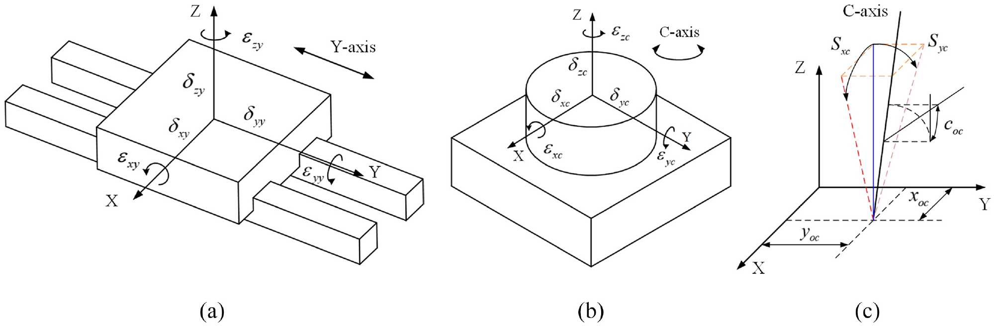
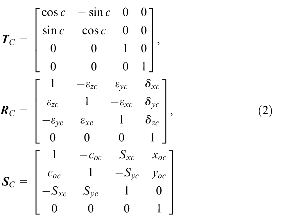
Definitions of geometric errors: (a) PDGEs of Y-axis, (b) PDGEs of C-axis, and (c) PIGEs of C-axis.
According to the definition of ISO 230-7,
27
the rotary axis takes C-axis as an example. Figure 2 shows the PDGEs
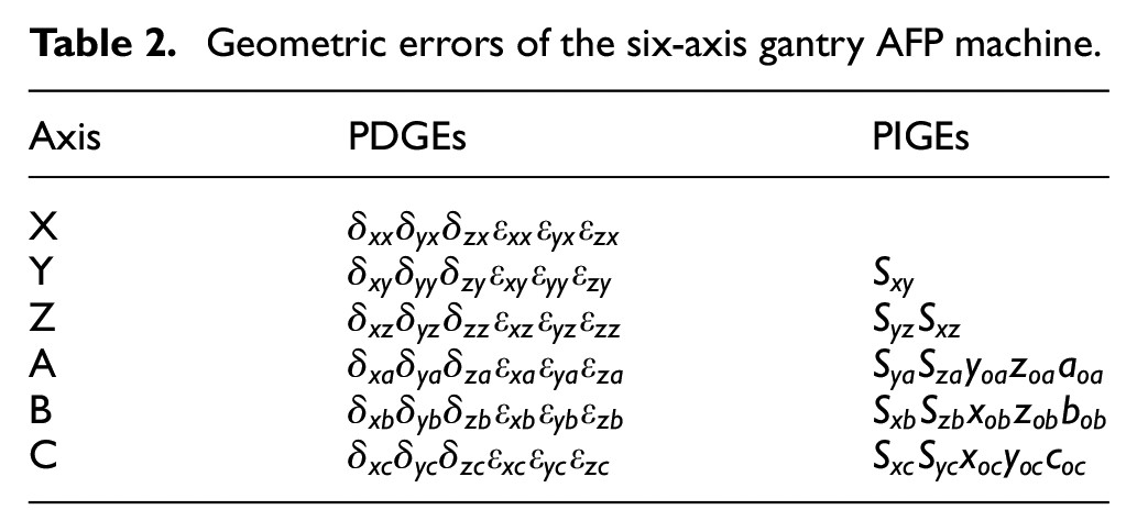
From the above analysis, we can see that there are 21 geometric errors in three linear axes
Geometric errors of the six-axis gantry AFP machine.
Volumetric error transfer model
In this research, the movement axes of the AFP machine are assumed to be rigid bodies, and a coordinate system is established on each movement axis. The HTM is used to describe the motion relationship and the volumetric error transfer relationship between the motion axes, thereby establishing the kinematics model and the volumetric error transfer model of the AFP machine. Considering the pose changes between the motion axes in the ideal and actual states respectively, an ideal kinematic model and a volumetric error transfer model can be obtained.
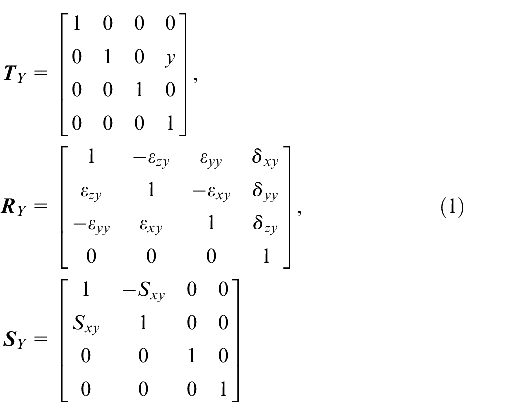
When the X-axis moves, the motion change matrix with errors of the

Where
In the same way, it can be obtained that when the I - axis ( I = Y, Z, B, A, C) moves, the motion change matrix with errors of the

Where
There is no relative movement of the EPR with respect to the C-axis. The relative pose of the
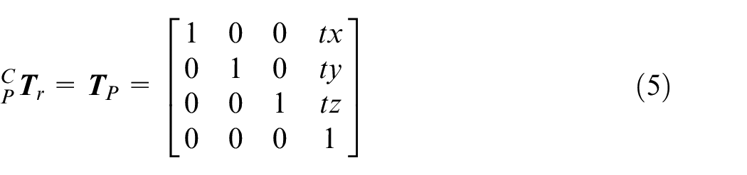
Where
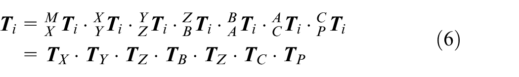
According to the motion change matrix of each coordinate system above, the ideal kinematics model of the AFP machine can be obtained as:
The volumetric error transfer model of the AFP machine is:

Define the orientation matrix of the TCP as
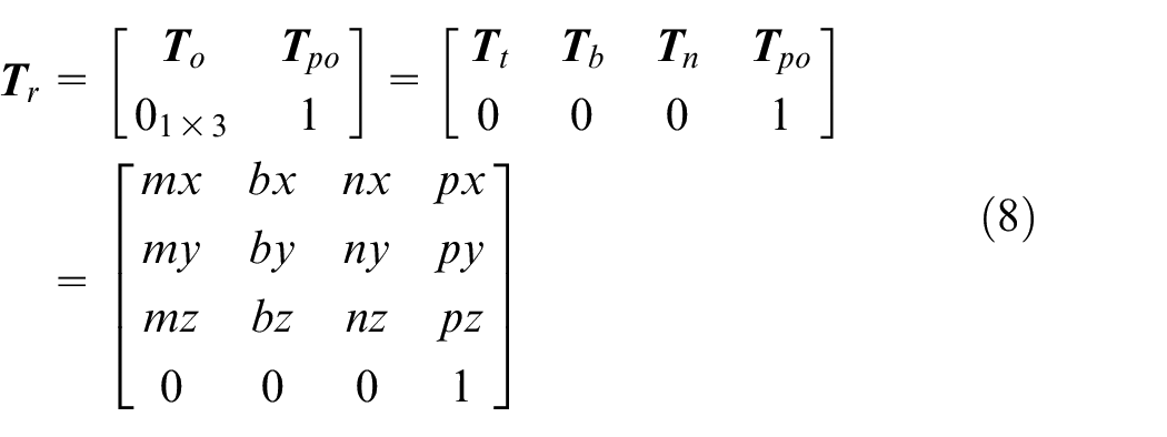
Where
Data capture
Measurement method
The laser tracker can directly measure the spatial three-dimensional coordinates of the measurement points, and its measurement function is mainly realized by a laser interferometer and two angle encoders. Because high-precision angle measurement is difficult to achieve in geometric measurement, the measurement accuracy of the angle encoders determines the measurement accuracy of the laser tracker. The geometric errors are measured using a laser tracker model Leica AT901-B, and the accuracy of its spatial measurement system is ±(
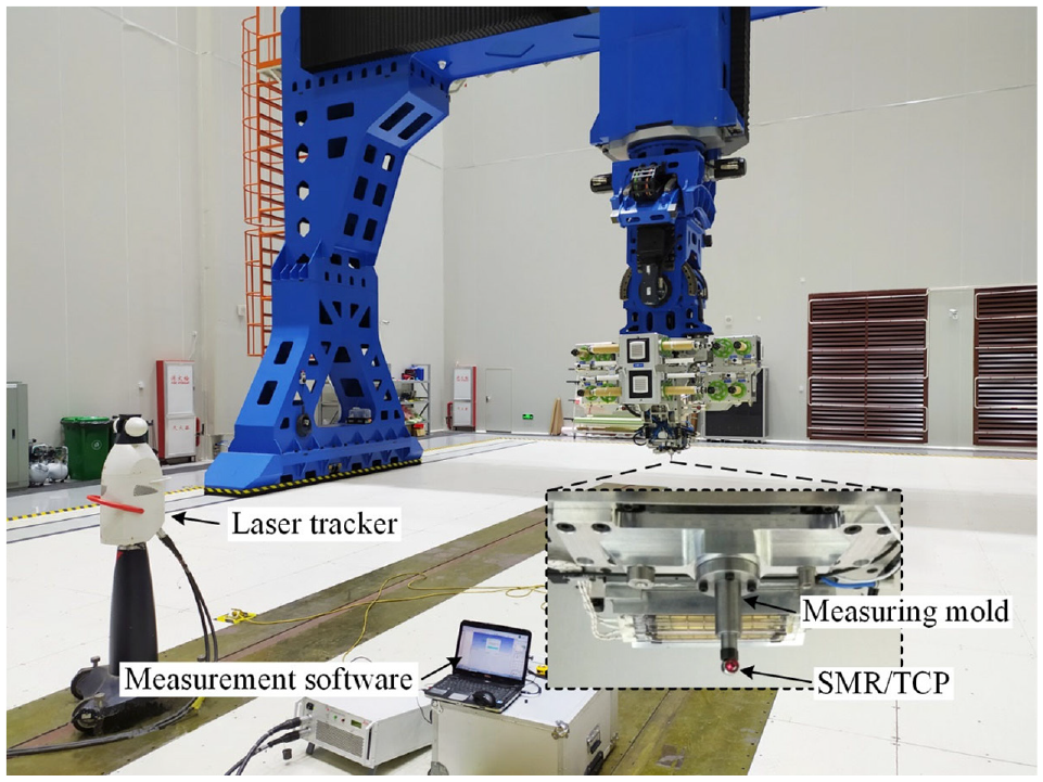
Geometric errors measurement process.
Measurement content
To improve the efficiency of error parameter identification, this paper uses the measurement data of random points as the basis to identify the error parameters of the AFP machine. The method of generating random points in space is as follows: Because the travel range of the X-axis is 18 m, using MATLAB to generate 200 random numbers in the interval
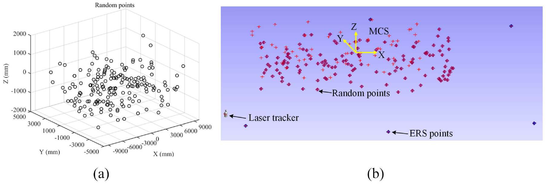
The random points: (a) The distribution of random points in the MCS generated by MATLAB, and (b) The random points in space measured by the laser tracker.
Error parameter identification
Object function
Error parameter identification is the core of the geometric accuracy calibration of the AFP machine. According to the volumetric geometric error transfer model described in Section 2. By choosing a suitable objective function, the difference between the measured values and the calculated values of the TCP is minimized.
The measured values of the random points corresponding to the joint value matrix
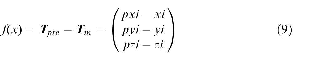
From the error function equation (9), the target function of the error parameter identification of the AFP machine can be obtained as:
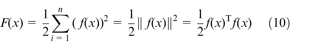
Where
Error fitting
Common fitting functions include Chebyshev polynomials, Legendre polynomials and simple polynomials. Chebyshev polynomials are a series of orthogonal polynomials defined recursively. The roots of the Chebyshev polynomials of the first kind can be used to reduce the Runge phenomenon to the greatest extent when polynomial interpolation is used. Using Chebyshev polynomials to perform regression analysis on the data can get a high-precision approximation, and it can also increase the fitting accuracy of the approximation function at the end of its domain. Chebyshev polynomials can be obtained by the following recurrence relationship:
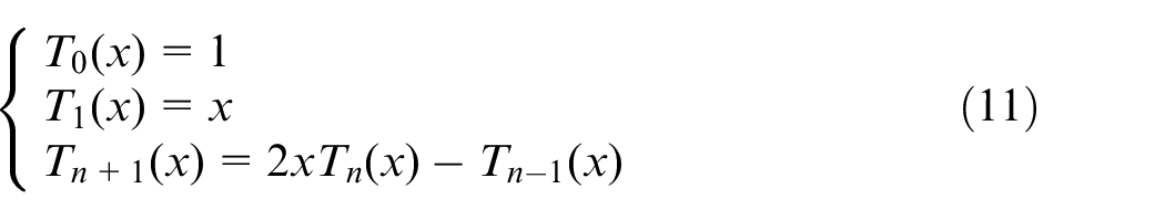
An n-order polynomial expansion using Chebyshev polynomials as basic functions can be expressed as:
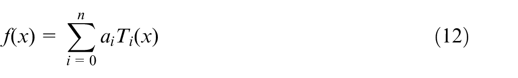
Where
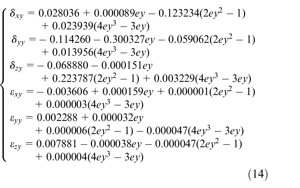
The choice of the order of the Chebyshev polynomials is important content. Generally speaking, the higher the order of the polynomial, the better the accuracy of the fitting. However, as the order increases, the polynomial is more affected by random errors (such as measurement noise), resulting in poor robustness. 13 Kruth et al. 28 pointed out that the geometric error changes slowly within the stroke of the motion axis, and a third-order polynomial can be selected to fit the error. Therefore, this paper chooses the third-order Chebyshev polynomials to fit the PDGEs of each axis. This turns the identification of PDGEs into calculating the regression coefficients of the fitting functions based on the measurement results of the TCP. Equation (13) shows the fitting of the six PDGEs of the Y-axis using third-order Chebyshev polynomials.
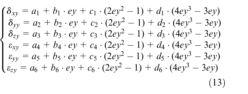
Where
It can be obtained from the above analysis that there are 144 error parameters in the fitting and identification of PDGEs of the six axes. For the assembled AFP machine, the values of PIGEs are constant, so it is not necessary to use Chebyshev polynomials to fit PIGEs, but can be directly identified by the error parameter identification algorithm. A total of 18 PIGEs need to be identified. Then there are 162 parameters to be identified in the error parameter identification.
Cross-validation
Cross-validation is a statistical method to eliminate the training bias caused by sampling randomness. V-fold cross-validation was proposed by Geisser in 1975. It is a cross-validation method based on partial segmentation of the data set. Molinaro et al. 29 concluded that the deviation will decrease with the increase of training set sample size. Among them, leave-one-out cross-validation produced the smallest deviation, and the deviation caused by the 10-fold cross-validation was very close to the deviation of leave-one-out cross-validation.
Due to time and efficiency limitations, only limited random point measurement data can be obtained. To better predict the geometric errors, this paper uses 10-fold cross-validation combined with the L-M method to train the kinematics model of the AFP machine, and comprehensively identify the geometric error parameters. The effective data of the random points measured by the laser tracker are 180 groups, then the effective data are randomly divided into 10 secondary data samples. In the process of error parameter identification, one secondary data sample is selected as the error prediction set, and the remaining nine secondary data samples are used as the error training set. Repeating the error parameter identification 10 times, and taking the average of the calculation results as the final error parameters. Figure 5 shows the 10-fold cross-validation schematic.
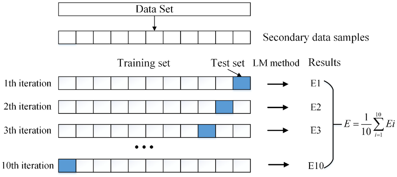
Ten-fold cross-validation.
In the process of error parameter identification, the change of the error parameters
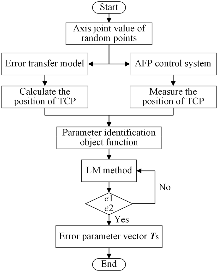
Flow chart of error parameter identification.
Optimization results
Identification of error parameters
By using the error parameter identification method described in Section 4, the calculation result
The influence of the value of convergence criteria and the order of Chebyshev polynomials on the residual errors of random points and the prediction errors of error prediction sets.
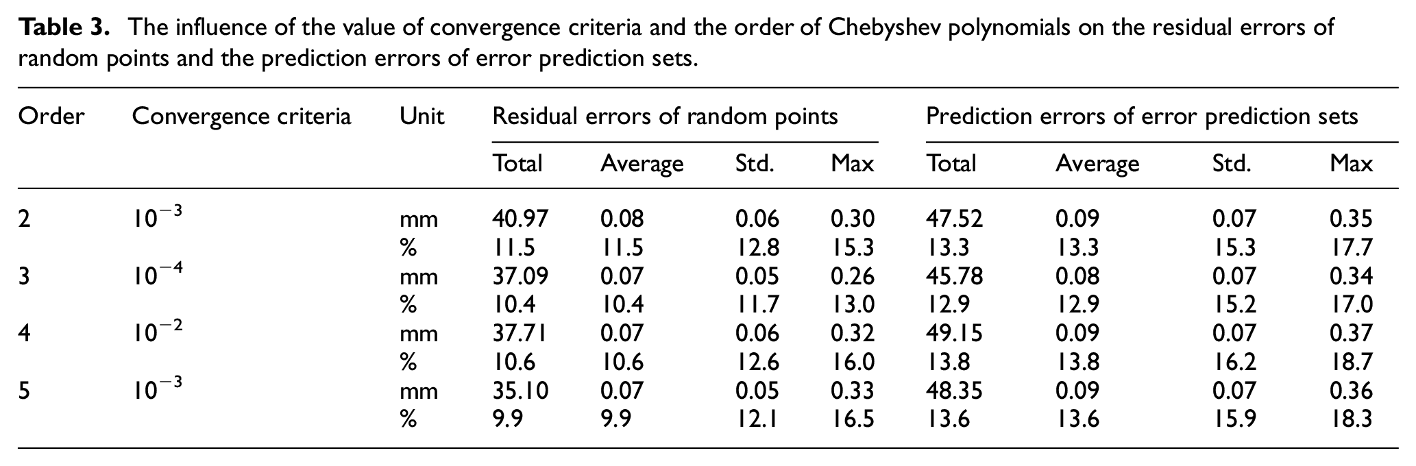
From the error parameter vector
For the gantry AFP machine, the two ends of the Y-axis guide rail are the supporting points, so the guide rail will bend downward under the gravity of the Z-axis and the AFP head. Therefore, the function image of the Z-direction straightness error
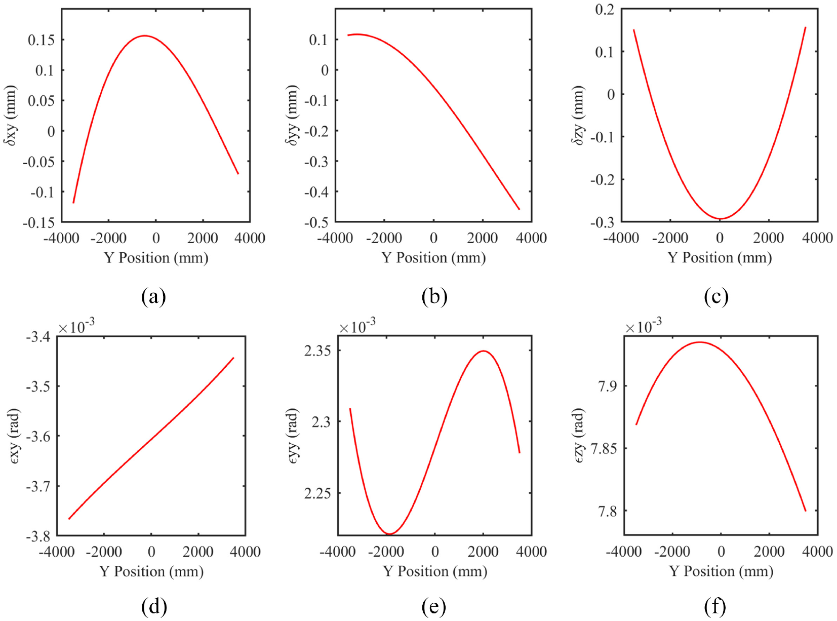
Six PDGEs function images of the Y-axis: (a) Function image of
Residual errors
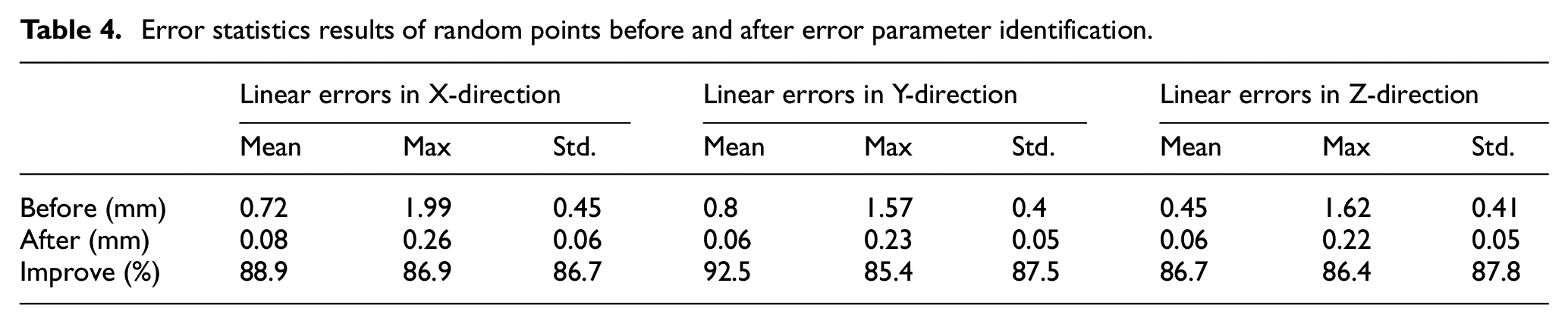
Figure 8 shows the comparison of the linear errors in three directions at random points before and after error parameter identification. To better express the result of the error parameter identification, Table 4 lists the error statistics results of random points before and after error parameter identification. The average error in the X-direction is reduced from 0.72 to 0.08 mm, a drop of up to 88.9%. The maximum error and standard deviation also decreased by 86.9% and 86.7% respectively. The result shows that the proposed volumetric error transfer model and error parameter identification method can significantly reduce the residual errors of random points (the maximum residual error is 0.26 mm), which is the best result that can be achieved under the premise of a laser tracker synthetic accuracy.
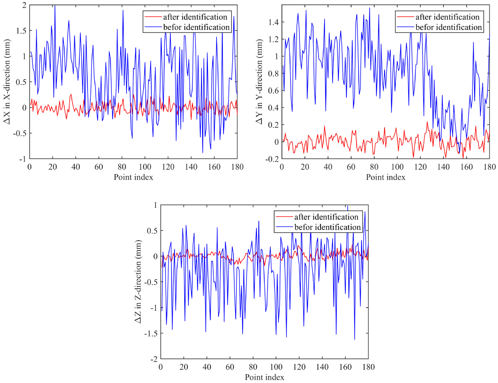
Comparison of the random point errors before and after error parameter identification.
Error statistics results of random points before and after error parameter identification.
Error prediction
Figure 9 shows the comparison between the prediction errors of error prediction sets and the residual errors of random points. The prediction errors at verification points in the error prediction sets are similar to the residual errors of random points, which shows that the volumetric error transfer model proposed in the article can accurately predict the volumetric errors of the AFP machine.
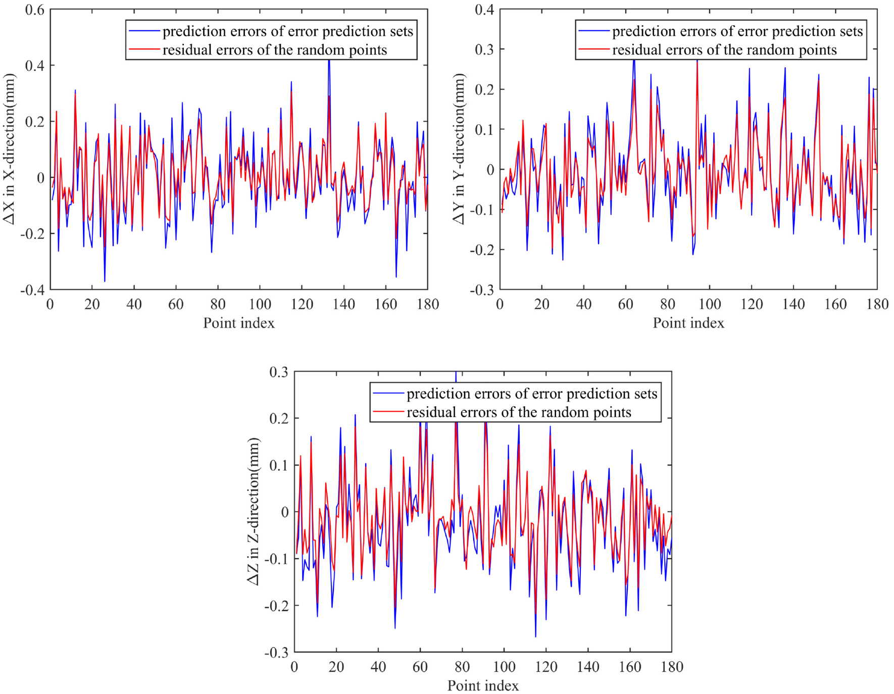
Comparison between the prediction errors of error prediction sets and the residual errors of random points.
Verification and analysis
Body diagonal verification
To quickly detect and evaluate the spatial geometric accuracy of the AFP machine, a method of rapid measurement of the body diagonals is proposed, which can also provide a reference for whether the geometric accuracy needs to be recalibrated. During the measurement of the body diagonals, the rotary axes are kept at the zero position, and only three linear axes are moved. At the same time, the laser tracker is used to measure the position coordinates of the TCP. Figure 10 shows the 84 sets of data obtained by measurement. Figure 11 shows the comparison of the body diagonal errors before and after error parameter identification.
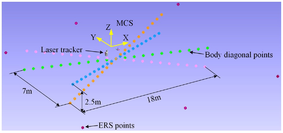
Measured data of the body diagonals.
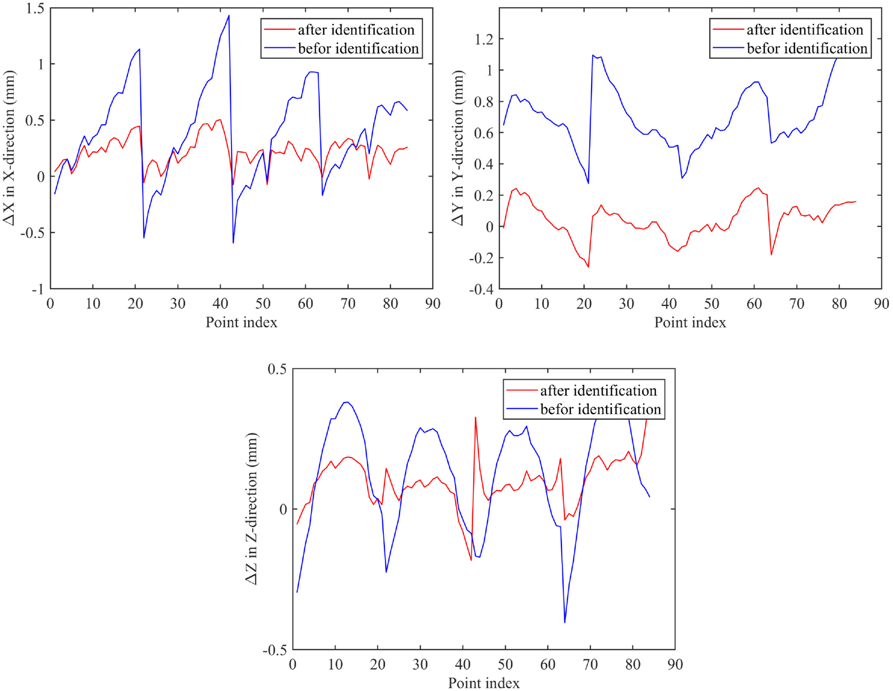
Comparison of the body diagonal errors before and after error parameter identification.
Verification of actual placement path
The six-axis gantry AFP machine has been successfully used in the manufacture of composite material components such as winglet, wing spar, pressure bulkhead, and wing panel. To better verify the usability of the volumetric error transfer model and the error parameter identification method in actual production. The actual laying path of a certain type of aircraft winglet is selected for verification. By measuring the position of the TCP at the G codes of the 19th path of ply 1 with 0° layering, 60 sets of measurement data are obtained. Figure 12 shows the comparison of the winglet actual placement path errors before and after error parameter identification. The average error in the X-direction is reduced from 1.61 to 0.82 mm, a decrease of up to 49%. It can meet the requirements of the AFP machine placement accuracy.
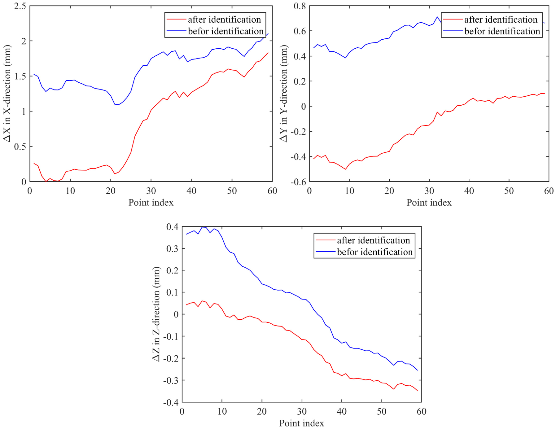
Comparison of the winglet actual placement path errors before and after error parameter identification.
Conclusion
This paper presents a novel method for kinematic modeling and error parameter identification of a six-axis gantry AFP machine. Firstly, using the MBS combined with 54 geometric errors proposed in the article, a volumetric error transfer model is established. Then, to eliminate the training bias caused by sampling randomness, 10-fold cross-validation combined with the L-M method is used to train the kinematic model of the AFP machine. According to the measured data of a laser tracker, all the PDGEs and PIGEs of the linear and rotary axes can be identified simultaneously, which improves the identification efficiency of error parameters and greatly reduces the residual errors of random points. Finally, corresponding experiments are carried out on the body diagonals and the actual laying path of the winglet. The experimental results show that the volumetric error transfer model and error parameter identification method can accurately predict the volumetric errors of the AFP machine, and can also meet the requirements of the AFP machine placement accuracy.
This shows that a reasonable selection of geometric error measurement and identification methods can quickly and efficiently calibrate the geometric accuracy of the AFP machine, thereby shortening the assembly and delivery time of the AFP machine, and can also provide a reference for the volumetric error compensation of the AFP machine.
Footnotes
Declaration of conflicting interests
The author(s) declared no potential conflicts of interest with respect to the research, authorship, and/or publication of this article.
Funding
The author(s) disclosed receipt of the following financial support for the research, authorship, and/or publication of this article: The authors gratefully acknowledge the financial support from Zhejiang Province Natural Science Foundation (Grant No. LQ20E050019), National Natural Science Foundation of China (Grant No. 51975520), National Natural Science Foundation of China (Grant No. 91948301), Key Research and Development Program of Zhejiang Province (Grant No. 2020C01039).