
Abstract
Error compensation technology as an economical and effective method for improving the machining accuracy of the machine tools has been widely applied in the manufacturing. How to quickly and accurately obtain machine tool error is an important prerequisite for achieving the above task. A laser tracker is adopted the multi-station and time-sharing measurement principle to achieve quick and accurate identification of the geometric errors of the machine tool. In this article, the error of single-station measurement of laser tracker is analyzed first, and then the principle and algorithm of multi-station and time-sharing measurement are given. Based on the kinematic model of the machine tool, the mapping relation equations between the space motion error and individual geometric error of the machine tool are established, and two different identification algorithms are derived, respectively. Meanwhile, the identification accuracy of two algorithms and the impact of different measurement areas and squareness errors on two algorithms are compared and analyzed in depth. The experiment results indicate that higher identification accuracy can be obtained by the second algorithm, and individual geometric error of the machine tool can be quickly and accurately separated by this algorithm.
Keywords
Introduction
With the development of modern manufacturing, the demand of machining accuracy of numerical control machine tool is increasing. The accuracy and stability of accuracy are important performance index of numerical control machine tools, so how to improve the machining accuracy is very important. Error compensation technology is an economical and effective method for improving the machining accuracy of machine tools,1–5 which has been widely used in the manufacturing. Studies have shown that geometric error accounts for large proportion of machine tool error. Meanwhile, geometric error is relatively stable,6–8 so it is easy to be compensated. Currently, compensation for the geometric errors of the machine tool has become an important way to improve the machining accuracy of machine tool.9–11 How to quickly and accurately obtain machine tool error is an important prerequisite for achieving the above task, which directly affects the effectiveness of error compensation.
At present, there are many methods for detecting the geometric error of numerical control (NC) machine tool. According to the different measurement principles, these methods can be divided into direct measurement (single error detection) and indirect measurement (comprehensive error identification). For single error detection, the instrument is used to directly detect the machine tool error, such as detecting the position error of machine tool by laser interferometer and gauge block. Each error of machine tool can be obtained by direct measurement,12,13 but the detection cycle is long. Meanwhile, different errors should be detected by different instruments, so the measurement cost is relatively high. For comprehensive error identification, the kinematic model of machine tool is used. The motion contour trajectory of machine tool or the volumetric position errors of measuring points during the working space of machine tool are measured, and then individual error can be separated according to machine tool error model, such as ball bar measurement,14,15 plane grating measurement 16 and one-dimensional (1D) ball array measurement. 17 In recent years, laser interferometer as a high-precision measuring instruments has been widely used in machine error detection.18,19 A variety of machine error detection methods based on the displacement measurement are developed, such as the 22-line method, 15-line method, 14-line method and 9-line method. In the above measurement methods, laser interferometer measurement is most commonly used. The laser wavelength is taken as the measurement reference, so this method has high accuracy. But the light adjustment process is more complex, and the detection cycle is longer, which directly affects the measurement efficiency. The other methods mentioned above also have some certain deficiencies in measurement efficiency and accuracy. Since 1980s, three-dimensional (3D) and dynamic tracking measurement has been developed rapidly to measure the motion of the robot and the large workpiece assembly.20–22 This method has the advantages of fast, dynamic measurement, 23 and it has been widely used in industrial measurement field.24–26 Compared with laser interferometer, a tracking mechanism is added to laser tracker to achieve the space coordinates’ measurement. 27 The light adjustment process is easy for this measurement, and the measurement cycle is shorter. Based on the advantage of this method, a laser tracker is adopted multi-station and time-sharing measurement principle to rapidly and accurately detect the geometric errors of machine tools in this article. The machine tool is controlled to move on the preset path in the 3D space, and a laser tracker is used to measure the same motion trajectory of the machine tool at different base stations. Then each position of base station and the space coordinates of measuring points can be determined according to Global Positioning System (GPS) principle. The mapping relation equations between the space motion error and individual geometric error of the machine tool are established, and individual error can be separated by solving the equations. According to whether the relative position deviations between different axes are considered in establishing the mapping model of error identification, two identification algorithms are derived, and the identification accuracy of two algorithms is compared and analyzed in depth. The experiment results indicate that higher identification accuracy can be obtained by the second algorithm, and individual geometric error of machine tool can be quickly and accurately separated by this algorithm.
Measurement principle of laser tracker
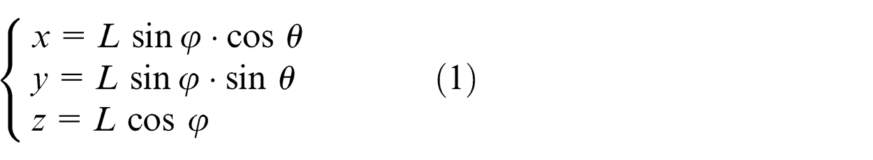
When the laser tracker is used, the measurement can be divided into single-station measurement and multi-station measurement according to the number of laser trackers. Single-station measurement adopts spherical coordinate measurement to calculate the space coordinates of a moving target as shown in equation (1)
The error transfer function is
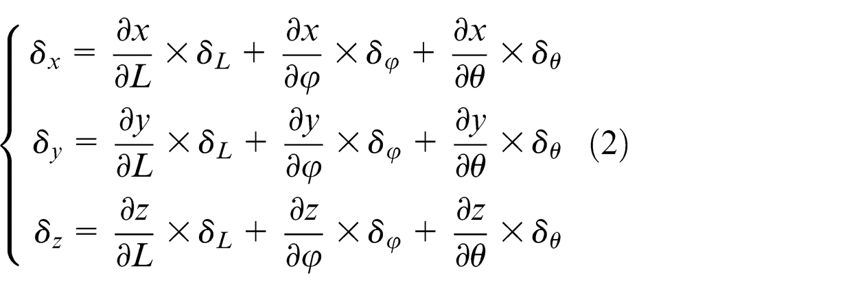
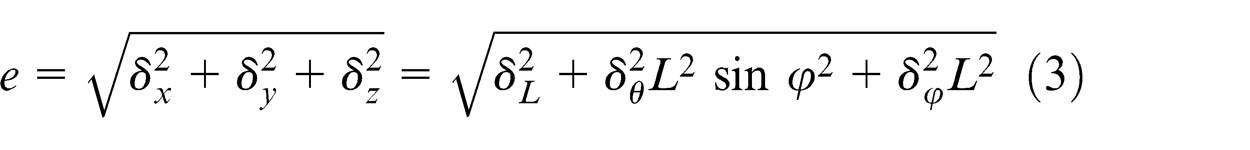
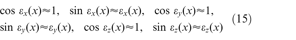
Then, the factors affecting the accuracy of single-station measurement of laser tracker can be analyzed as follows. In the measurement, the horizontal angle and elevation angle of a measuring point are assumed as
Space measurement errors of a measuring point (mm).
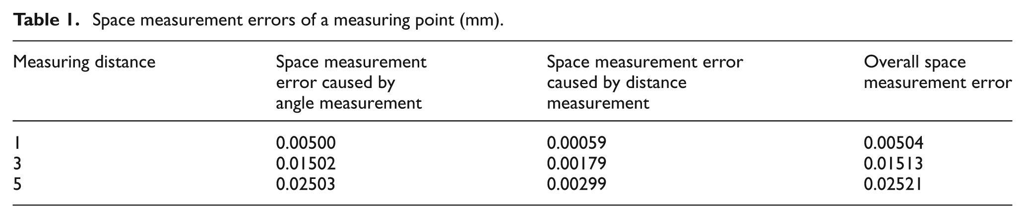
It can be seen from Table 1 that the coordinate measurement error is mainly caused by angle measurement. Meanwhile, the angle measurement error will be further amplified with the increase in distance, which directly affects the overall accuracy of the spatial coordinates. 28 When the single-station measurement is used to detect the high-accuracy machine tool, the measurement accuracy cannot be guaranteed due to the impact of angle measurement error.
Principle and algorithm of multi-station and time-sharing measurement
In order to avoid the influence of angle measurement error,29,30 the multi-station and time-sharing measurement is adopted in the article. A laser tracker is used to measure the target point at different base stations, and the spatial coordinates of measuring point can be determined by the laser ranging information measured at multiple base stations. Only distance is involved in the measurement, and the impact of angle measurement error is avoided. Therefore, this measurement has higher accuracy. Figure 1 shows the measurement principle of the machine tool by multi-station and time-sharing measurement. In the measurement, the machine tool is controlled to move on a preset path in the 3D space, and a laser tracker is used to measure the same motion trajectory of the machine tool at different base stations. The corresponding measurement algorithm is given as follows.
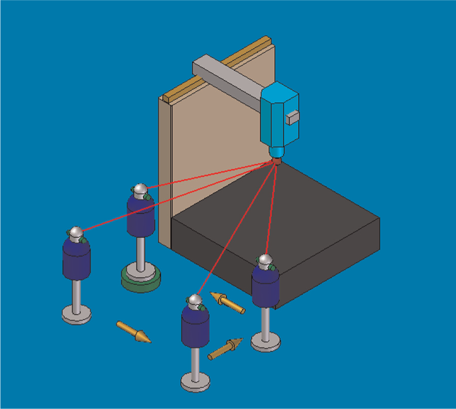
Principle of multi-station and time-sharing measurement.
Taking the calibration of base station
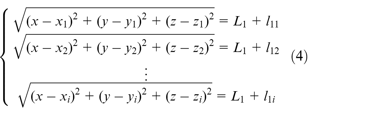
The least squares method can be used to solve the above nonlinear redundant equations.
31
Let
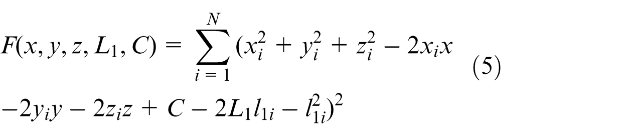
The analytical method is used to solve the least squares problem, then we can obtain
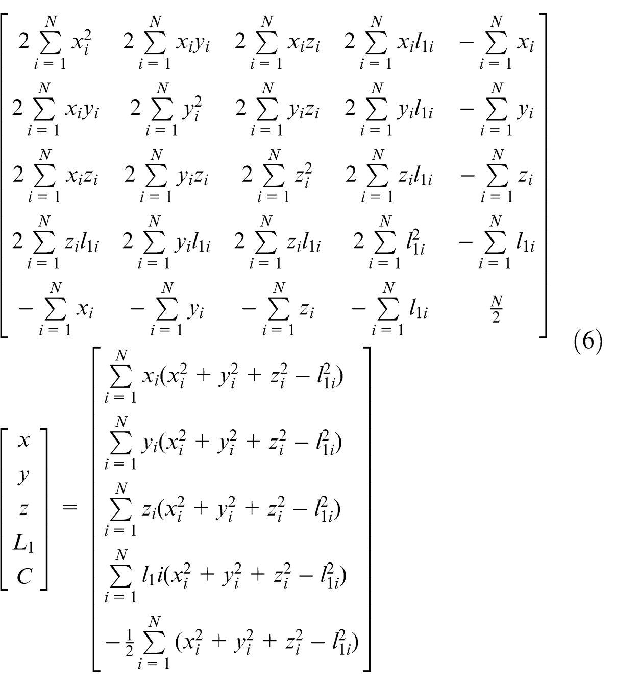
Repeating the above process, the position of other base stations can also be calibrated. When the positions of four base stations are obtained, the actual coordinates of each measuring point
Geometric error identification for machine tool
There exists six error components for each moving part of machine tool, and Figure 2 shows six geometric errors of
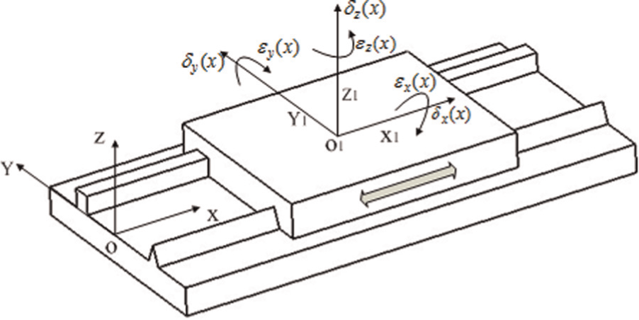
Six geometric errors of
There are 21 geometric errors for three-axis machine tool, and how to accurately identify each error is particularly important. Here, the comprehensive identification method is adopted. Based on the kinematic model of machine tool,32,33 the mapping relation equations between the space motion error and each geometric error of machine tool are established, and each error can be separated by solving the equations. The error identification principle is shown in Figure 3. Based on the identification principle of nine-line method, 34 a identification algorithm by laser tracker is derived. For this algorithm, the total 21 geometric errors of three-axis machine tool cannot be identified simultaneously, and the squareness error is determined by the corresponding straight errors identified. To identify 21 geometric errors of machine tool simultaneously, a new identification algorithm is proposed considering the relative position deviations between different axes in establishing the mapping model of error identification. Two identification algorithms are deduced as follows.
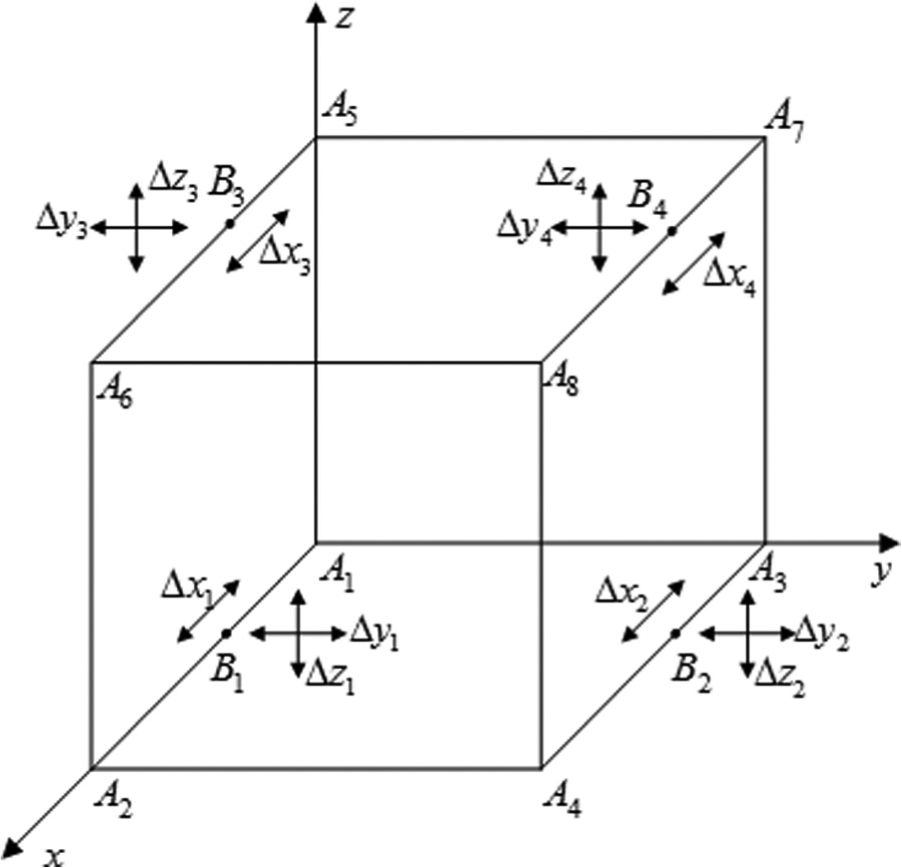
Error identification principle of machine tool.
First algorithm
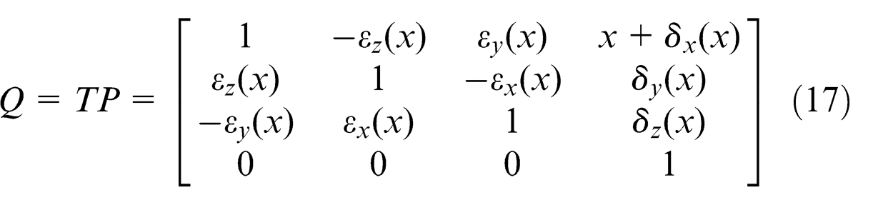
When the machine tool moves the distance
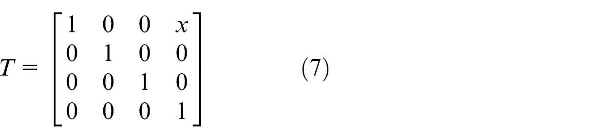
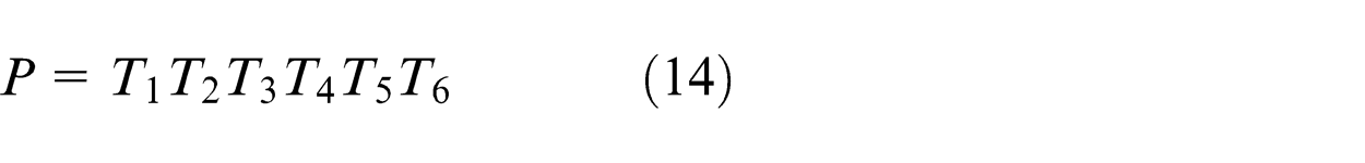
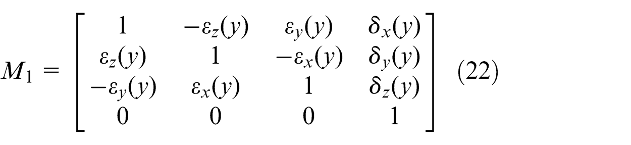
In the motion of machine tool, the homogeneous transformation matrixes caused by position error
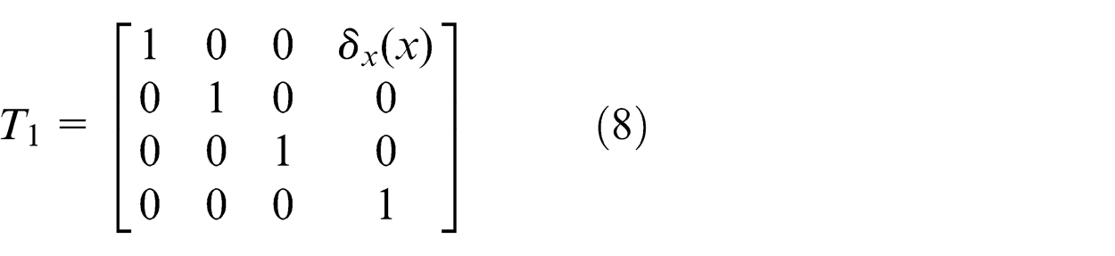
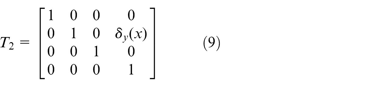
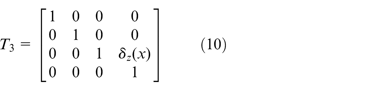
So the total error transformation matrix is
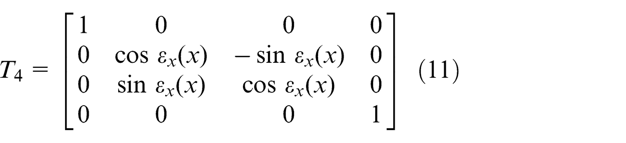
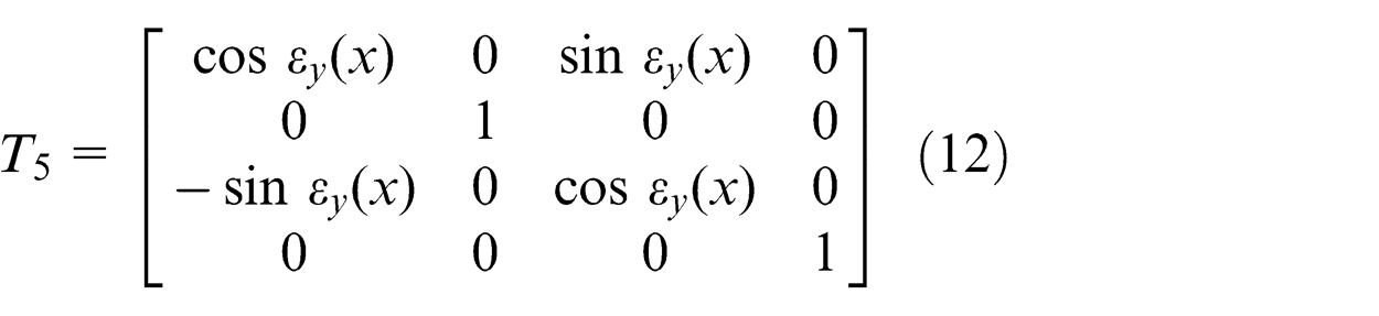
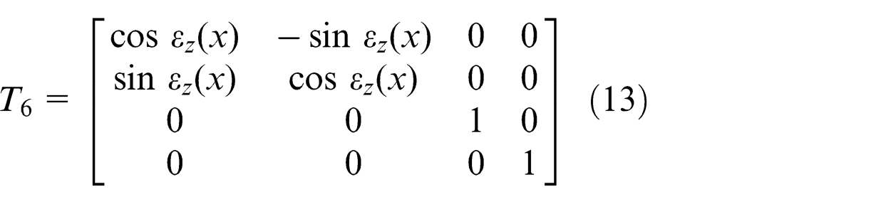
Roll error
Then we can obtain
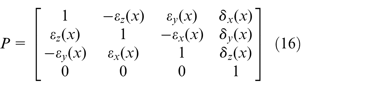
The total transformation matrix is
So the motion error of machine tool at measuring point
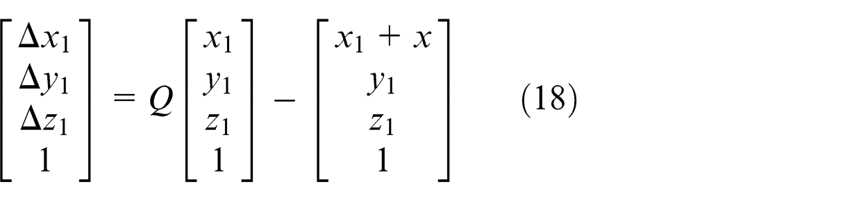
Then we can obtain
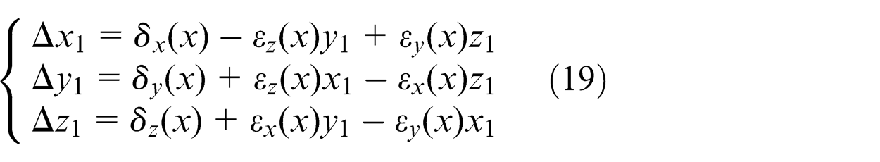
Similarly, the motion error equations at measuring point
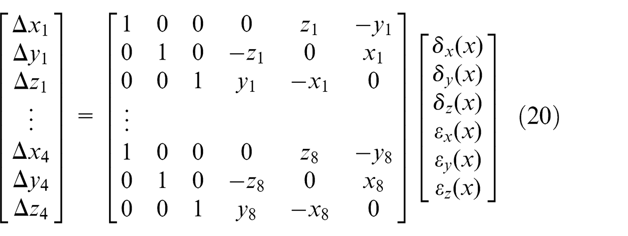
In equation (20), there are six unknown parameters to be identified, and the number of equations is 12. So the least squares method can be used to solve the equations using space motion error of the machine tool measured by laser tracker at each measuring point, and then each geometric error of
Using the same method, six geometric errors of
The squareness error is determined by the corresponding straight errors in the above error identification process. Currently, some methods adopt this identification principle. When the machine tool moves along
Second algorithm
The error identification of
Error identification of
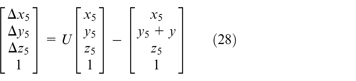
When the machine tool moves the distance
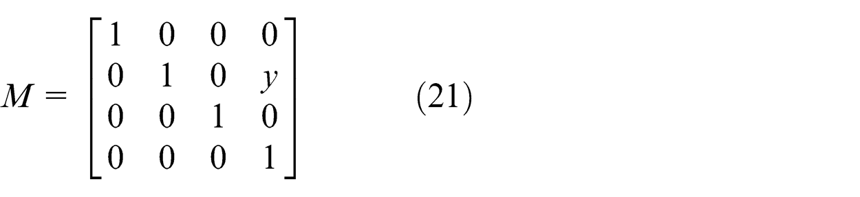
There exist position error
The error caused by the squareness error
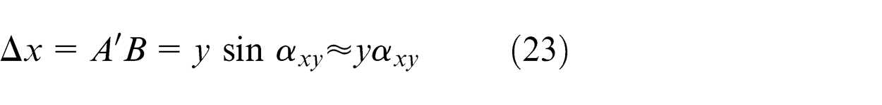
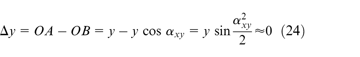
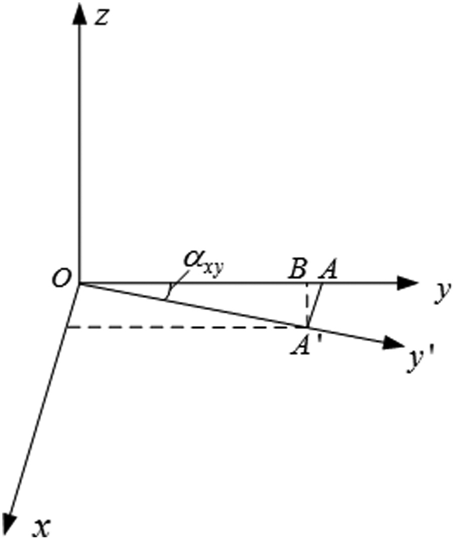
Motion error caused by squareness error
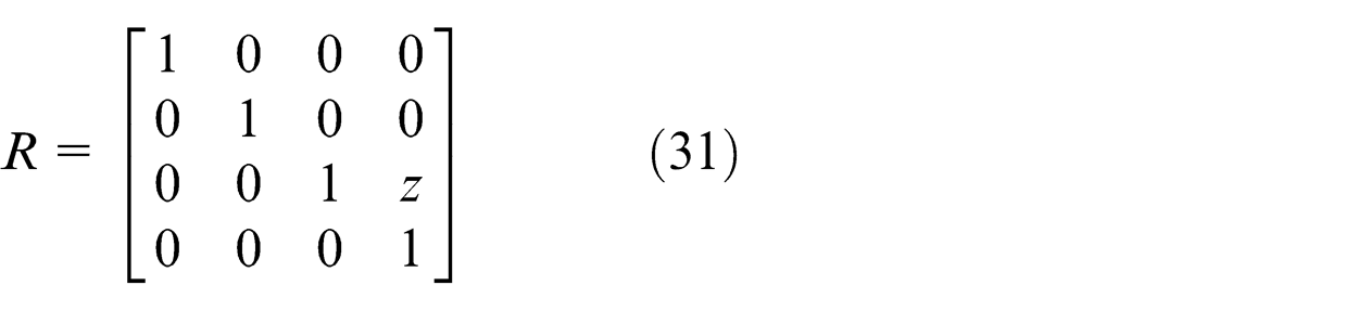
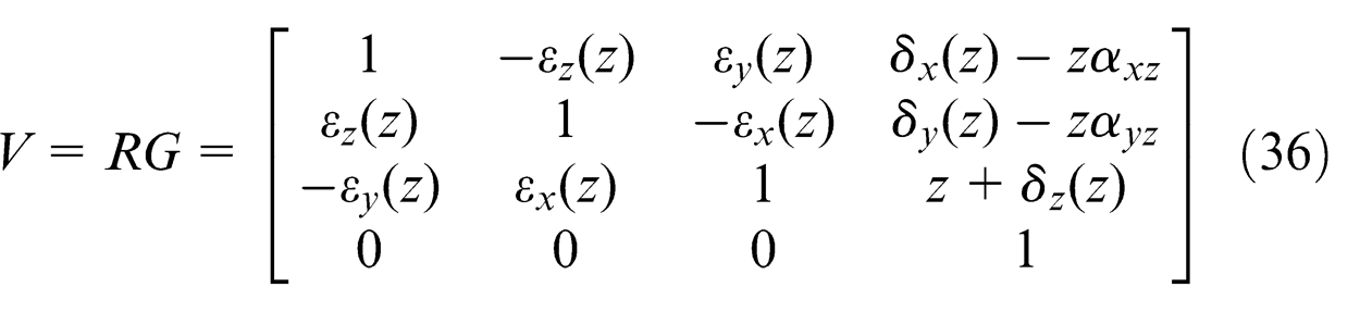
The homogeneous transformation matrix caused by squareness error
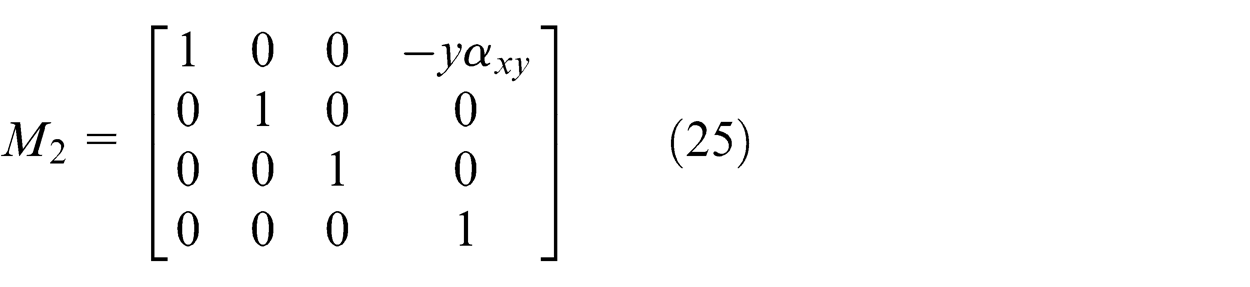
So the total error transformation matrix is
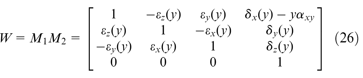
The total transformation matrix with moving along
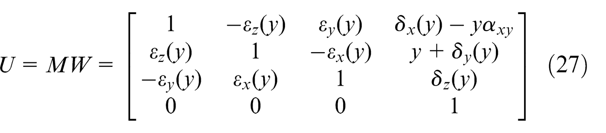
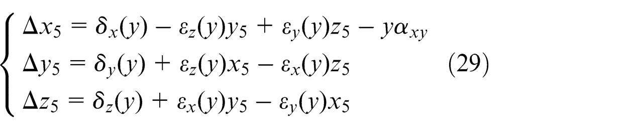
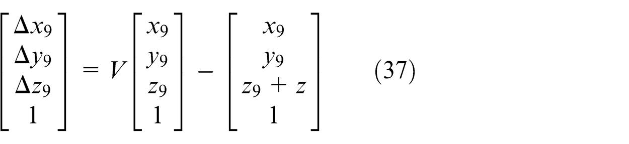
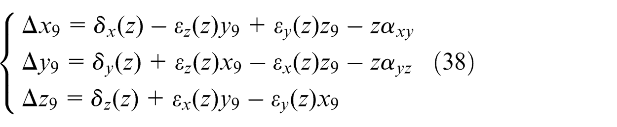
So the motion errors of machine tool with moving the distance
Then we can obtain
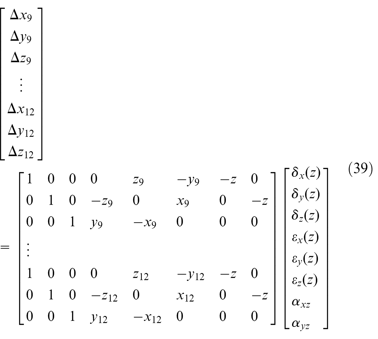
Similarly, the motion error equations with moving the distance
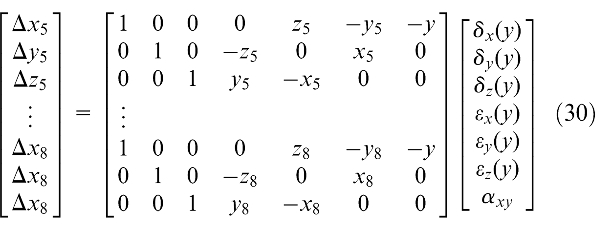
Six geometric errors of
Error identification of
When the machine tool moves the distance
There exist position error
The homogeneous transformation matrixes caused by squareness error
The total error transformation matrix is
The total transformation matrix with moving along
So the motion errors of machine tool with moving the distance
Then we can obtain
Similarly, the motion error equations with moving the distance
By solving the above equations, six geometric errors of
Simulation for error identification of machine tool
Taking identifying the error of
Without considering the effect of random error during machine tool motion
In order to analyze the impact of different measurement areas and different squareness errors on two identification algorithms of
Under different measurement areas
In the simulations, the motion areas of the machine tool are defined by 1000 mm × 1000 mm × 1000 mm, 2000 mm × 2000 mm × 2000 mm and 3000 mm × 3000 mm × 3000 mm, respectively. Meanwhile, nine measuring points are uniformly distributed on each edge of the cube. The squareness errors between
Maximum value of each individual geometric error of
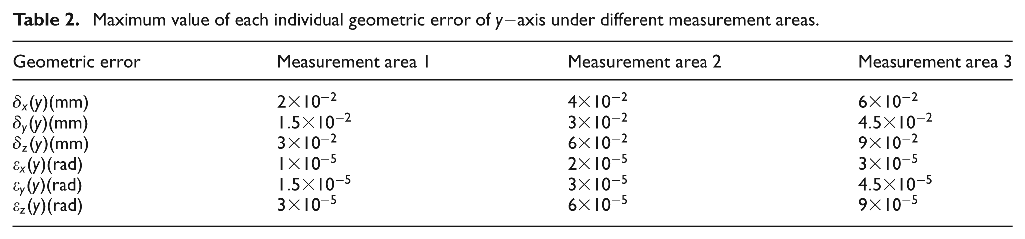
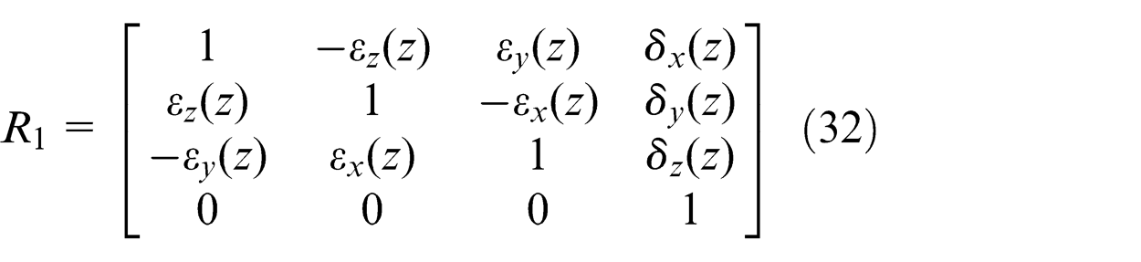
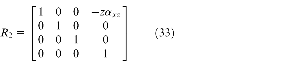
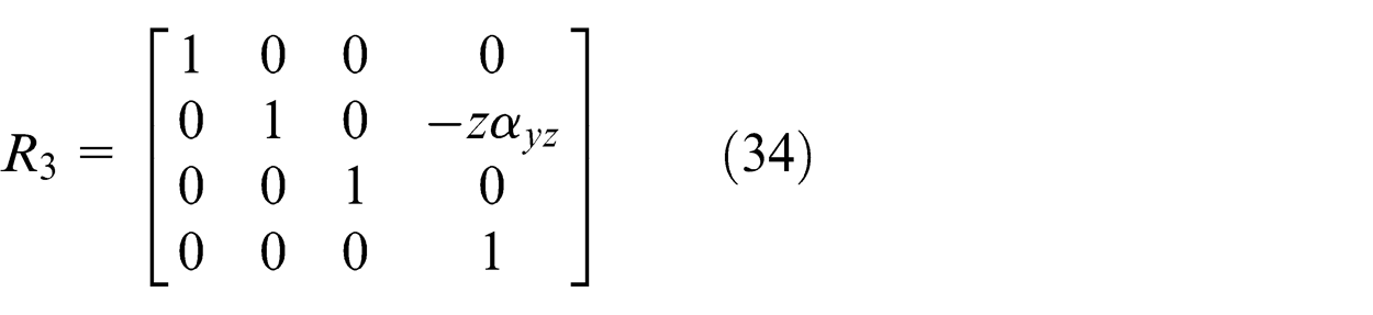
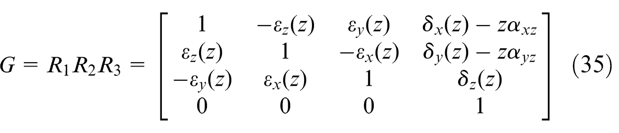
According to the volumetric error model of three-axis machine tool,
35
the space motion error
The simulations results indicate that there exists certain identification deviations using the first algorithm, and Table 3 shows the identification deviations of some geometric errors of
Identification deviations of some geometric errors of
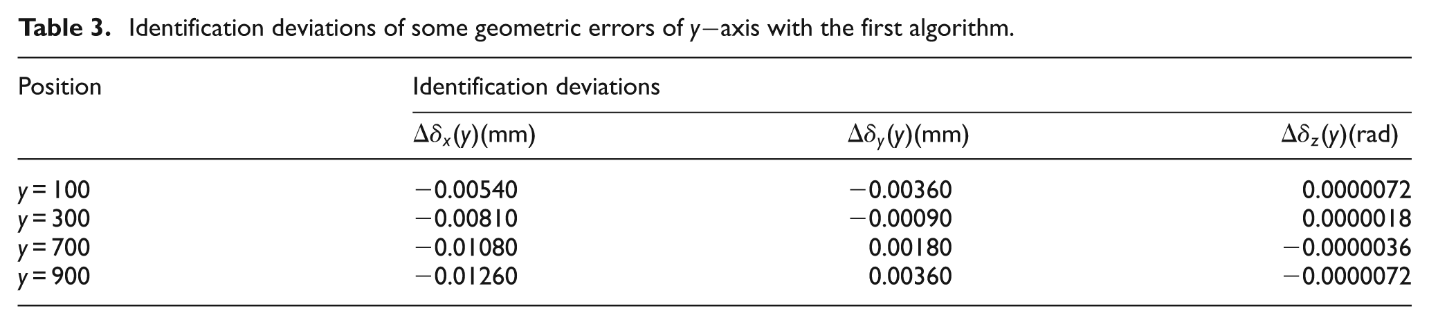
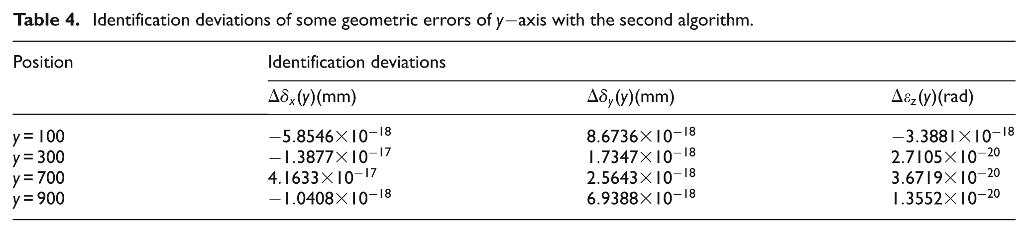
Each geometric error of
Identification deviations of some geometric errors of
Taking identifying the straightness error
Identification deviations of straightness error
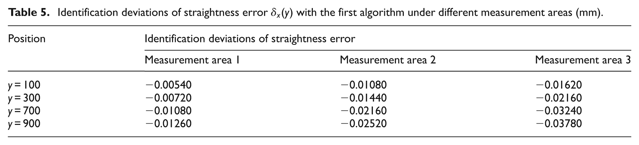
Identification deviations of straightness error
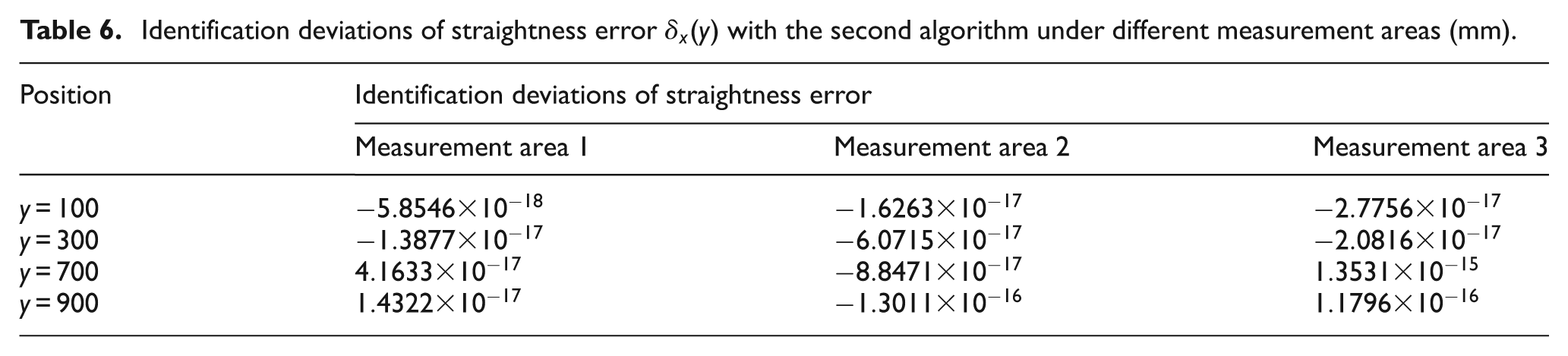
From Table 5, there exist certain identification deviations using the first algorithm. Meanwhile, the identification deviations are becoming larger with an increase in the measurement areas. From Table 6, individual geometric error of
Under different squareness errors
The motion areas of the machine tool are defined by 1000 mm × 1000 mm × 1000 mm; six geometric errors of
Different squareness errors under three conditions.
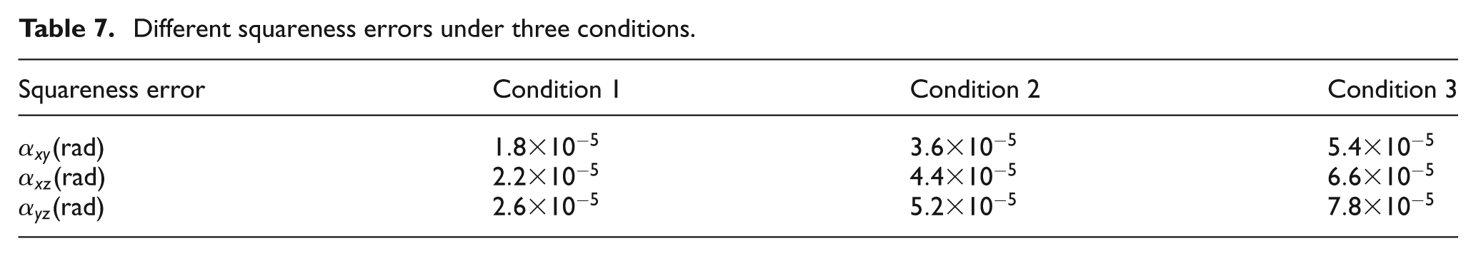
The simulations show that individual geometric error of
Identification deviations of straightness error
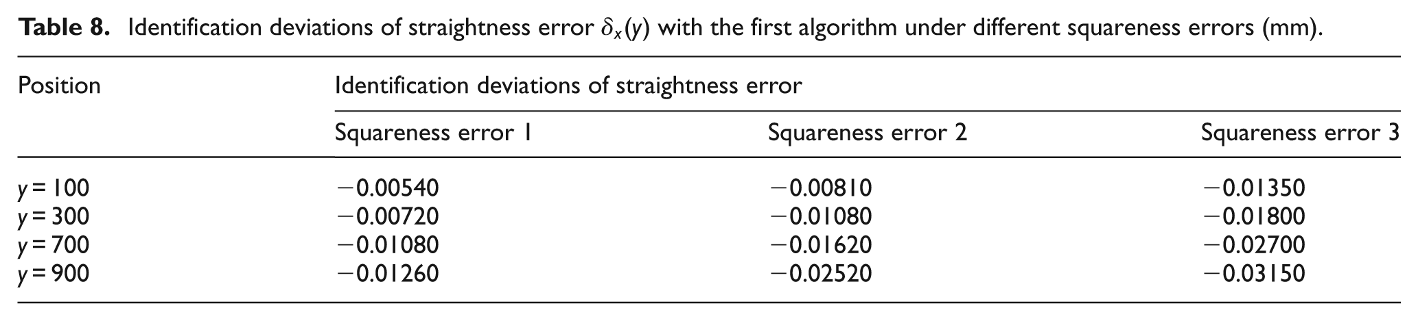
Identification deviations of straightness error
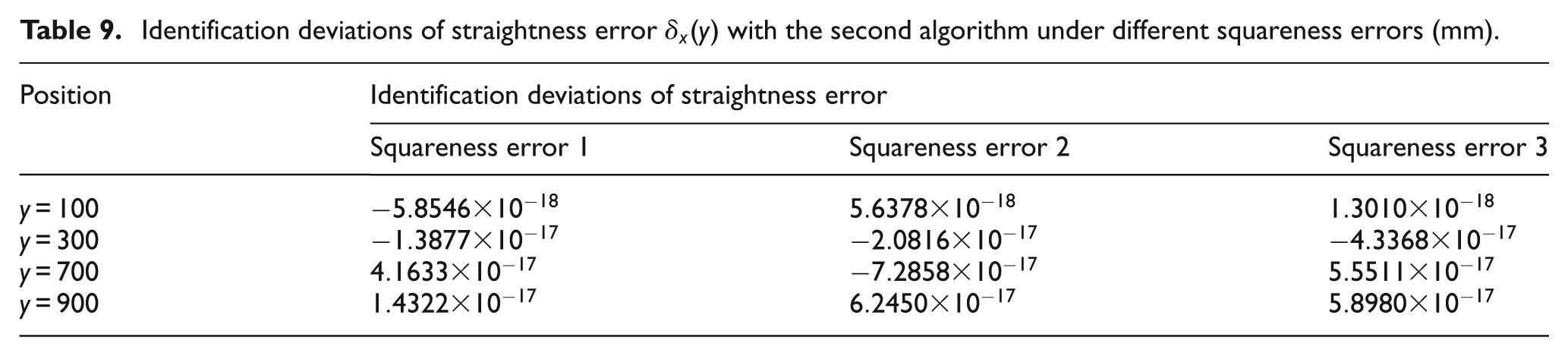
It can be seen from Tables 8 and 9 that individual geometric error of
Considering the effect of random error during machine tool motion
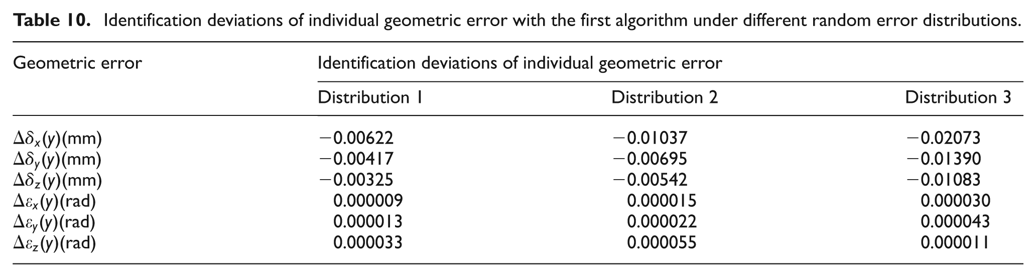
Under this condition, a random error is added to the theoretical motion error at each measuring point. To simplify the calculation, the random error during machine tool motion obeys a random normal distribution within [0, 3 μm], [0, 5 μm] and [0, 10 μm], respectively. Tables 10 and 11 show the identification deviations of individual geometric error of
Identification deviations of individual geometric error with the first algorithm under different random error distributions.
Identification deviations of individual geometric error with the second algorithm under different random error distributions.
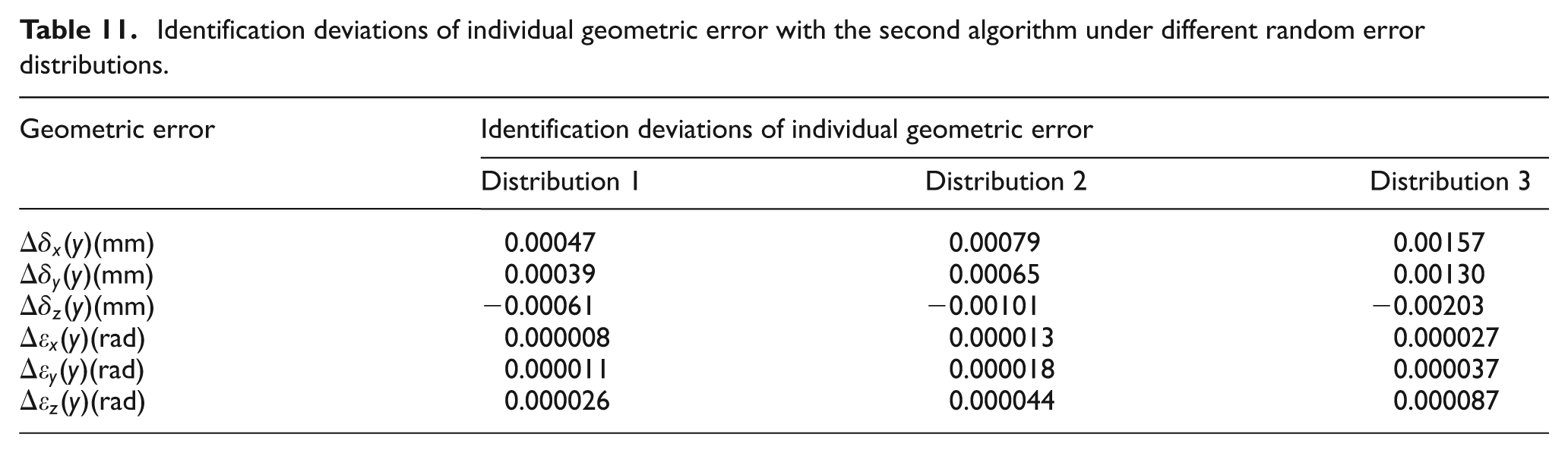
It can be seen from Tables 10 and 11 that the identification deviations with second algorithm is significantly smaller than the identification deviations obtained by the first algorithm. For the second algorithm, the maximum identification deviation is −0.00061 mm for
Experimental verification
A laser tracker is adopted multi-station and time-sharing measurement to identify the geometric errors of a gear grinding machine as shown in Figure 5. The measurement area is 800 mm × 400 mm × 500 mm, and a laser tracker is used to measure the same motion trajectory of the gear grinding machine at four base stations. In order to reduce the influence of random errors of the gear grinding machine on the measurement results, the motion trajectory of the gear grinding machine is measured for three times at each base station. The total measuring time is about 5 h, and 21 geometric errors of the gear grinding machine can be identified using the measurement algorithm and identification algorithm mentioned above. Figures 6 and 7 show the part error curves of
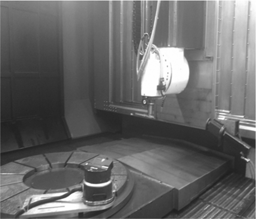
Geometric error detection of gear grinding machine.
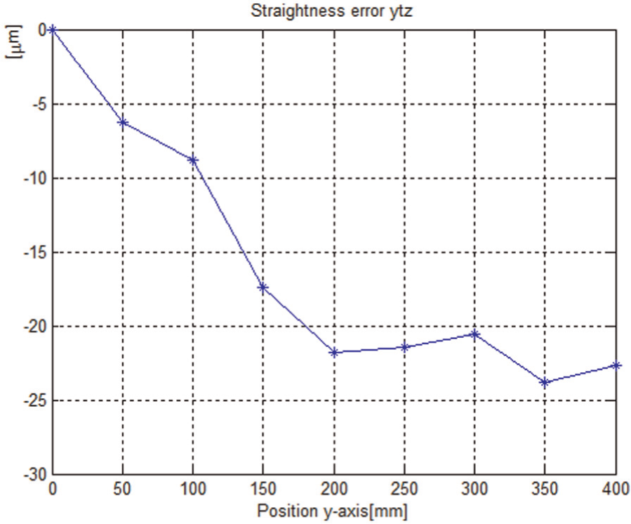
Straightness error of
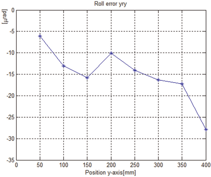
Roll error of
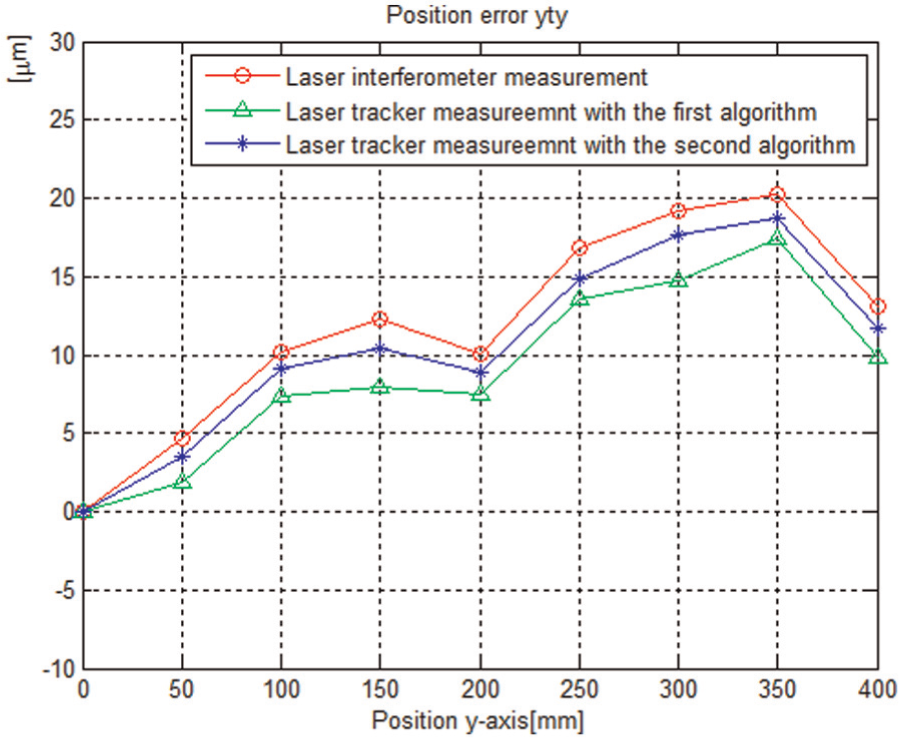
To compare the identification accuracy of two algorithms derived, the position error of
Comparison of two identification algorithms.
Comparing with the identification result of the first algorithm in Figure 6, the position error of
Conclusion
The factors affecting the accuracy of single-station measurement of laser tracker are analyzed. To avoid the influence of angle measurement error, a laser tracker is adopted the multi-station and time-sharing measurement to identify the geometric errors of machine tool.
Two identification algorithms of geometric error of machine tool by laser tracker are deduced. For the first algorithm, the total 21 geometric errors of three-axis machine tool cannot be identified simultaneously. For the second algorithm, the total 21 geometric errors of three-axis machine tool can be identified simultaneously.
The identification accuracy of two algorithms and the impact of different measurement areas and different squareness errors on two algorithms are compared and analyzed in depth. Simulations and experiments indicate that the identification accuracy of the second algorithm is higher than the identification accuracy of the first algorithm, and individual geometric error of the machine tool can be accurately separated by the second algorithm.
Footnotes
Declaration of conflicting interests
The authors declare that there is no conflict of interest.
Funding
This research was supported by the National Natural Science Foundation of China (Grant No. 51305370) and the Fundamental Research Funds for the Central Universities (Grant No. 2682014BR017).