
Abstract
Magnetic Abrasive Finishing (MAF) is an advanced finishing process that has the prominent characteristics such as the ability to machine complex surfaces with complex geometry. Geometric tolerances are among the important parameters in the qualitative evaluation of machining parts. Due to the large number of abrasive edges participating in the finishing process, it is very difficult to achieve accurate geometric tolerances in the MAF process. This problem is especially considerable in workpieces with low machinability such as nickel based superalloys. In this study, the effect of process input parameters such as feed rate, rotational speed, and working gap on surface roughness and geometric parameters such as circularity and cylindricity of the external surfaces of an Inconel 718 shaft was investigated. The results indicate that surface quality and geometric tolerances improve with increasing rotational speed. However, the increase of rotational speed by a certain amount leads to turbulence in the movement of abrasive particles and no significant changes are seen. As well as, by increasing feed rate, surface roughness and geometric tolerance increase. Furthermore, with the working gap increasing due to the reduction of magnetic abrasive brush width, circularity, and cylindricity tolerances increase, but smoother surface roughness is achieved.
Keywords
Introduction
Demand for precision parts lead to new challenges for manufacturing industries to provide better surface quality and closer dimension tolerance at a low cost. In order to meet these stringent requirements of industries, new processes are being developed. The common finishing processes like lapping, honing, and grinding employ high normal stresses during the finishing operation. This may produce surface and sub-surface damage, recast layer and change in the microstructure of the finished surface. 1 Therefore, for ensuring defect of typical finishing processes, in the past decade, many researchers have attempted to introduce a new finishing process to achieve a closer tolerance and more accurate parts.
Magnetic Abrasive Finishing (MAF) is one of the advanced finishing methods in which the material removal process is performed through abrasion by using abrasive particles. In this process, a workpiece is exposed to a magnetic field with respect to a certain distance between the workpiece and magnetic source. 2 Then, the abrasive tool, which consists of magnetic particles and abrasive particles, are applied. Finally, material removal is carried out at the nano-scale with the rotational motion of the workpiece (Figure 1). Magnetic Abrasive Finishing is a process which gives flexibility to precisely control the polishing pressure. Furthermore, the surface roughness and geometrical tolerances are two important aspect of this process.3,4
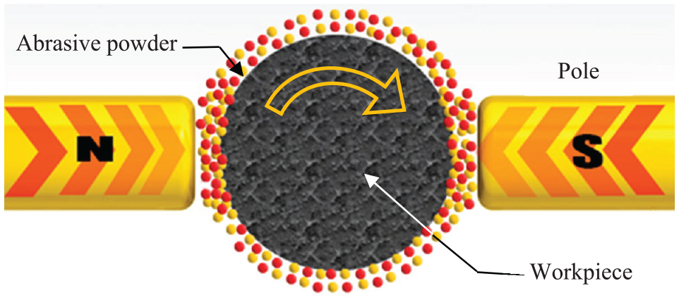
Material removal mechanism of MAF process.
The study of different effective parameters in the MAF process continue to be of great interest which some researchers attempted to investigate the effect of different process input parameters on the different aspects of the specimen. 5 Singh et al. 6 defined the required experiments using the Taguchi design of experiment approach and found that voltage and working gap are the most effective parameters of the MAF process on steel’s surface roughness. Pandey and Pandey 7 presented double disk magnetic abrasive finishing (DDMAF) method and they investigated the process parameters such as working gap, abrasive mesh number and the rotational speed of the primary magnet. They found that high polishing speed, low working gap, and high mesh number of alumina abrasive contributed in obtaining improved surface roughness. In another study with the same magnet and the same abrasives, Khalaj Amineh et al. 8 applied ultrasonic vibrations on the MAF tool, which was immersed in water for polishing the internal surface of cylindrical aluminum specimens. As a result of the vibrations, the surface becomes smoother in a shorter finishing time. It was revealed that decreasing the working gap due to increasing magnetic forces, gives rise to the chances of damage to the surface. In the most recent works by Kajal et al., 9 the MAF process was applied to finish components with a complex shape such as revolver barrel and they investigated the effects of input parameters on helical groves of the barrel. In another attempt, Rotational-magnetorheological abrasive flow finishing (R-MRAFF) process was used to machine freeform surfaces, which improve the surface roughness compared to conventional processes. 10 Additionally, Nagdeve et al.11,12 applied the MAF process on another complicated component with a freeform surface (knee joint implant) which was made up of Co-Cr-Mo and they succeeded in achieving a smooth and uniform surface with a measure of 75 nm roughness. Another recent paper, studied polishing of silicon wafer as a brittle material which is extensively used in semiconductors by using magnetic abrasive finishing process. 13 It was found that material removal rate and percent improvement in surface roughness increase with increasing rotational speed and decreasing working gap.
Numerous researches have studied the effect of MAF input parameters on different aspects of the specimen such as surface roughness, surface properties, fatigue strength, geometrical shapes, and different workpiece materials.14–16 However, the novelty of this research work is that this is first time the effects of AFM process input parameter on workpiece geometrical parameters investigated. Besides, nickel based superalloys are an important group of high-temperature materials which are used in the most precise section of aerospace industries and the rarest number of study have been conducted to investigate the applicability of MAF process in the case of superalloys.
Based on the results of previous studies,17–20 it is clear that the nano-scale chip removing process in the MAF process is carried out by numerous cutting edges of abrasives (Figure 2). Therefore, process control is complicated compared to other processes in which machining are performed using a single-edge tool. On the other hand, workpiece dimension control is another challenge of the MAF process. Thus, the aim of this study is to investigate the effects of the MAF input parameter on surface roughness and geometrical tolerance of nickel-based superalloy (Inconel 718) and provide new approaches to make this process more controllable. In the present study, the effect of the input parameters of the process such as rotational speed, feed rate and working gap on surface roughness, circularity, and cylindricity of the Inconel 718 will be investigated for the first time and several experiments will be presented to prove the results.
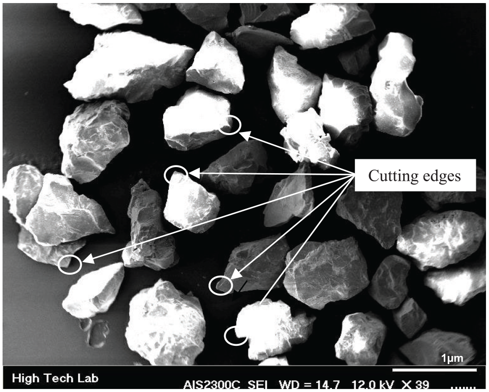
Silicon carbide abrasive particles.
Experimentation
Due to the wide range of MAF applications, there is no specific and unique machine for this process and in the present research, as others have also claimed in their study, it is necessary to design and manufacture a machine for the process. So, a machine, as shown in Figure 3, was designed in this research to perform the study. The machine is made up of three main sections including the main body, workpiece rotational system, and magnetic poles and each consist of subsections. The body was designed in a way to have maximum rigidity and an adjustable-speed servo motor was used to provide the rotational motion of the tool and the linear motion of electric magnets. Furthermore, two electric magnets were used to provide magnetic force and they were placed on the sides of the workpiece (Figure 3).
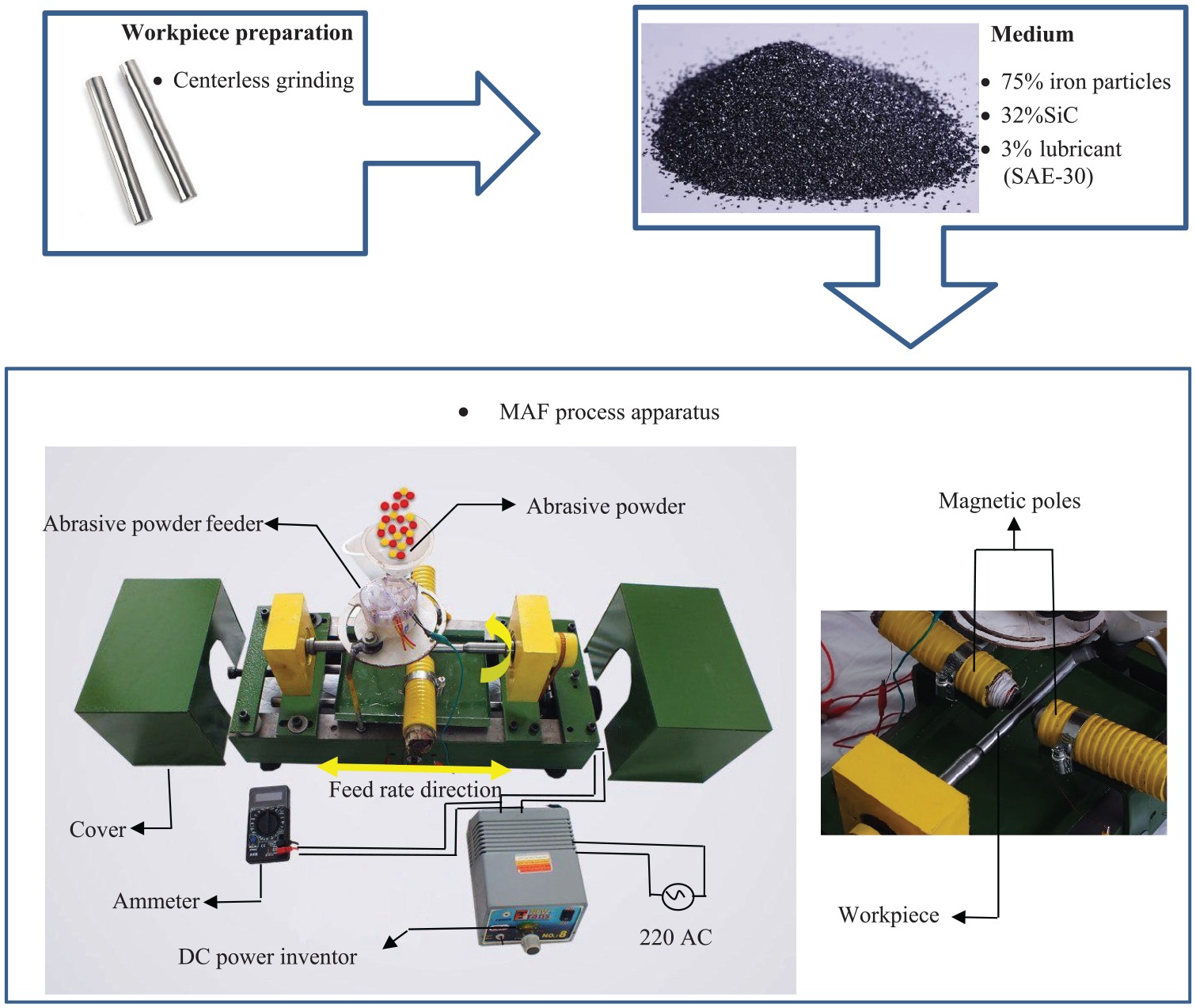
Diagram of the experimental set-up.
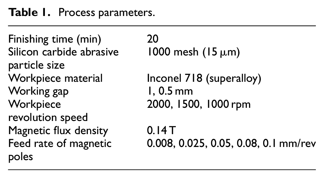
Table 1 summarizes the MAF process conditions. In this study, each specimen was polished for 20 min in different rotational speeds, feed rates, and working gaps. The flux density opted 0.14 Tesla which measured by digital Gauss meter (model: TD8620). It is worth mentioning that each experiment was repeated five times.
Process parameters.
Before applying the MAF process, all specimens have been ground by centerless grinding machine to obtain the same range of surface roughness, circularity and cylindricity. The initial surface roughness, circularity and cylindricity of specimens were between 0.8–0.6, 1–3, and 2–5 µm respectively. Furthermore, the abrasive powder used in this study was composed of silicon carbide (SiC) (90 Rockwell A hardness), iron particles and lubricant in the ratio of 75% iron particles, and 32% SiC particles by weight. In addition, 3% of the total weight lubricant (SAE-30) is added to the abrasive brush to get adhesiveness among iron particles and SiC particles. The reason for choosing this composition is that the abrasive brush in MAF process contains of magnetic particles (Iron) and abrasive particles (silicon carbide) with different duties. As result, by increasing the percentage of magnetic particles, abrasive brush led to be more coherent and abrasion ability is reduced and vice versa. Overall, the optimum percentage of mixture according to the experiences during the experiment determinate as mentioned above. Silicon Carbide (SiC) is the only chemical compound of carbon and silicon. The reasons of selecting SiC, Fe as abrasive particles are that it was originally produced by a high temperature electro-chemical reaction of sand and carbon. Silicon carbide is an excellent abrasive material. It has low density, high strength, low thermal expansion, high thermal conductivity, high hardness, and excellent thermal shock resistance.
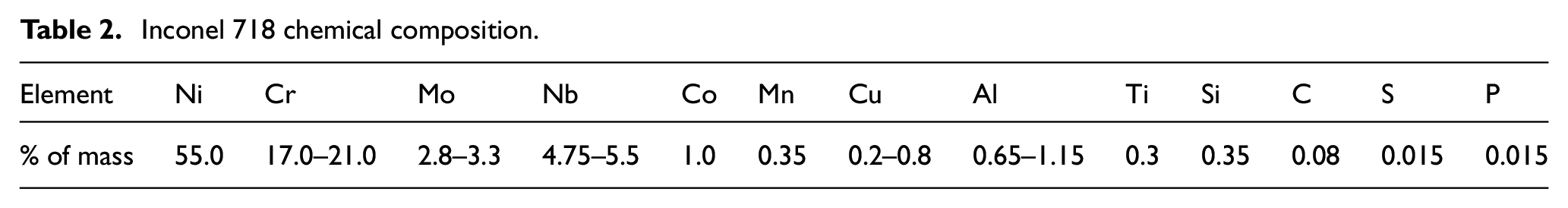
The specimen material (also known as UNS N07718) is a precipitation hardening nickel-based superalloy that combines superior corrosion resistance and strength with 37 Rockwell C hardness. This superalloy contains significant levels of molybdenum, iron, columbium, and niobium, along with lesser amounts of aluminum and titanium (Table 2). These specifications make Inconel 718 rods a popular choice for numerous industries. The alloy is ideal for hot extrusion tooling and parts, such as casings, bolts, fasteners, rings, and instrumentation components. Inconel 718 bars are also frequently used in fabricating aerospace and aircraft components. Inconel 718 is a recent yet widely used industrial metal in the present time. It is taken as a refractory superalloy as it can be employed at temperatures above 600°C. It is used by 50% of weight only in aircraft turbojet engines in the form of major parts of disks, blades, and casing of high pressure part of compressor and disks and blades of turbines.
Inconel 718 chemical composition.
Results and discussion
Surface roughness
Figure 4 illustrates the setup equipment of the surface roughness measuring process. The specimen positioned by Vee blocks and roughness of the surfaces were measured by the Mitutoyo portable surface roughness tester. It should be noted that the measurement direction is in the opposite of the tool lay. The cut-off length is chosen at 2.5 mm which the choice of this amount is common in finishing operations (according to ISO 4288). As well as, to better investigating the surface properties, contact surface roughness meter, Scanning electron microscope (SEM), and atomic force microscope (AFM) utilized.
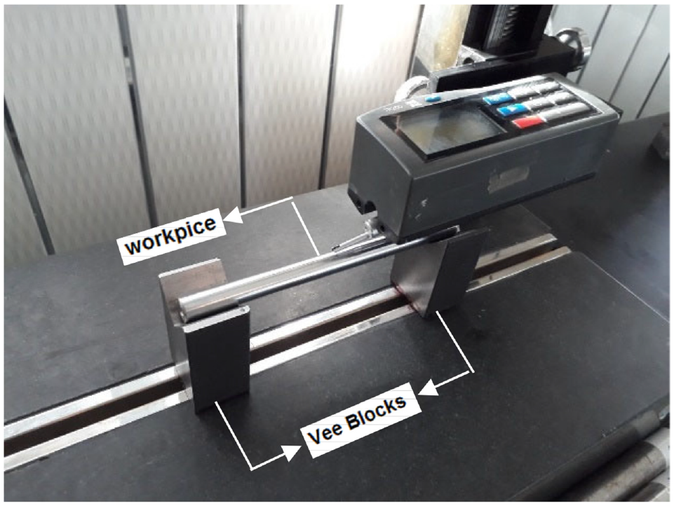
Surface roughness measurement equipment.
Figure 5 shows percentage change of surface roughness (
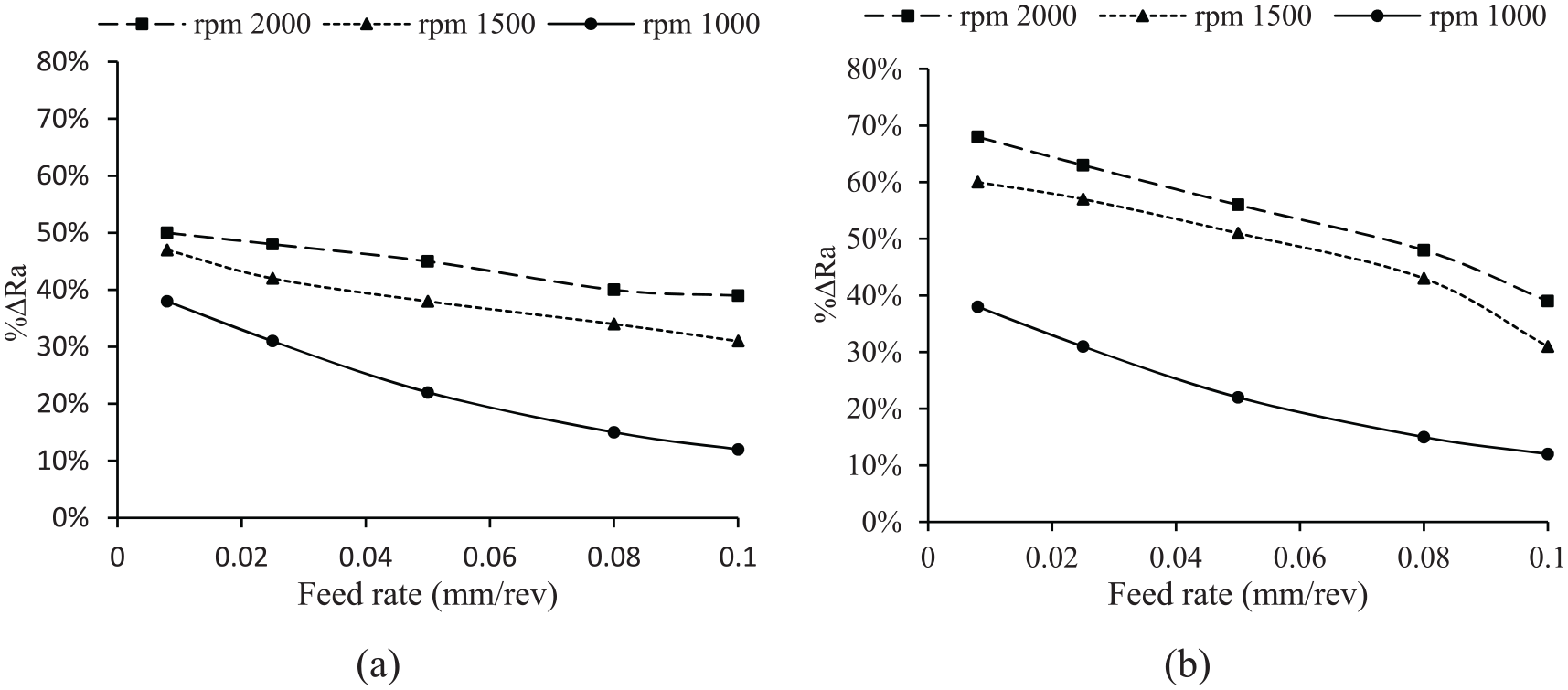
Effect of rotational speed and feed rate on surface roughness: (a) working gap = 0.5 mm and (b) working gap = 1 mm.
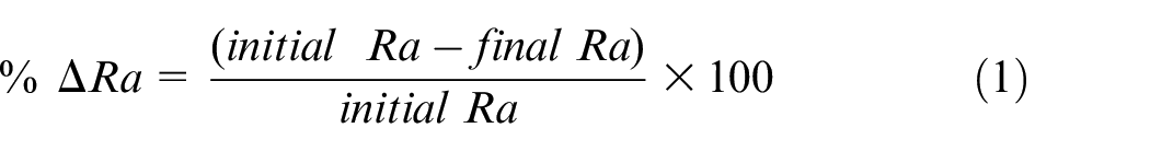
Equation (1) describes the effect of input parameter by %ΔRa which reported the changes of surface roughness instead of surface roughness. For example, as reported by Figure 5 a specimen with initial surface roughness of Ra = 0.8 processed by MAF at feed rate = 0.25 mm/rev, rational speed = 1000 rpm, and working gap = 0.5 mm the resulted surface roughness was Ra = 0.55 so, according to equation (1) %ΔRa = %31. By increasing the feed rate to = 0.5 mm/rev, surface roughness increased to Ra = 0.62 as result %ΔRa reduced to = %22. This mean that surface changes improve by increasing feed rate decreased. Generally, by increasing rotational speed and working gap surface roughness decreased and alternatively, by increasing feed rate, surface roughness increased and a rougher surface is obtained. Surface quality variations are much more intense with the change of feed rate at low rotational speed. In other words, the surface quality gradient increases intensively at a low rotational speed, compared to higher speeds. For instance, in Figure 5(a) at a rotational speed of 1000 rpm, the difference of %ΔRa at 0.08–0.1 mm/rev feed rates is about 30%; however, this value is approximately 10% at the rotational speed of 2000 rpm. Thus, the effect of feed rate on surface quality reduces with increasing rotational speed. The remarkable point in the diagrams is the noticeable change in the improvement of surface quality at the rotational speed range of 1000–1500 rpm. Though, with increasing rotational speed, the centrifugal force acting on abrasive particles increases, hence the abrasive particles get detached from the flexible magnetic abrasive brush (FMAB). 6 Due to this phenomenon in the MAF process, the percentage changes of surface roughness in the rotational speeds range of 1500–2000 rpm were low. Furthermore, Figure 5 shows that surface quality is improved with an increase in the working gap. The surface quality improvement is due to the reduction of magnetic force caused by the increase of the working gap between the electric magnet poles and workpiece. 21 The radial (Fr) and normal (Fz) components of magnetic force are evaluated by the following expressions 22 :
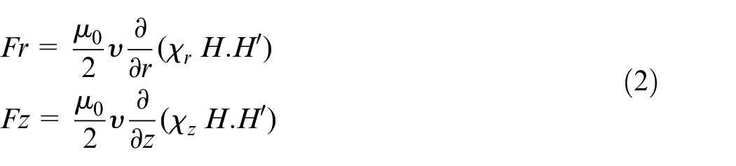
Where

This way, the rate of material removal reduced with the magnetic force reduction, which makes chips to be removed with smaller size and as a result, a smoother surface is obtained this will also increase the process time to achieve the desire Ra value. Likewise, the increasing magnetic force causes an increase in the material removal rate, thus leading to increase the surface roughness. The depth of penetration
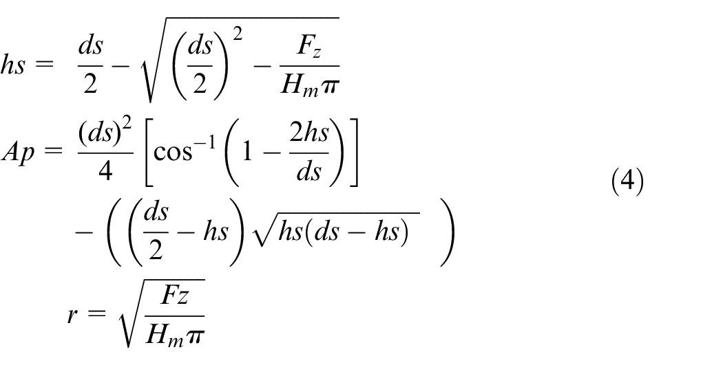
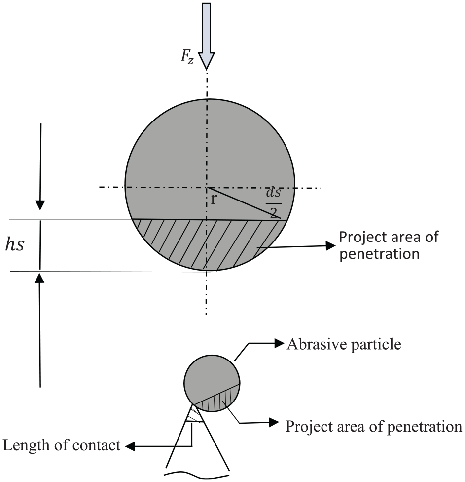
Schematic diagram of abrasive grain showing depth of penetration and projected area of penetration Fz is normal magnetic force.
Where
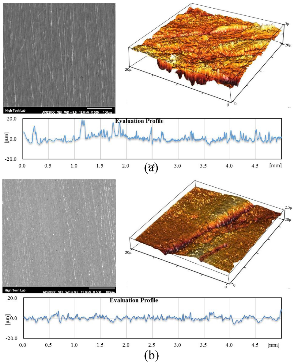
Figures 7 to 9 show the surface profile and 3D surface topographic images of the MAF process, which respectively shows the changes of surface quality versus rotational speed changes, feed rate, and working gap. It is clear that surface quality improves with the rotational speed increasing and surface quality reduces with the feed rate increasing. It is evident from Figure 9 that the depth of the surface burrs reduces by increasing the working gap.
SEM image of surface profile and effect of rotational speed on surface roughness. Working gap: 1 mm, feed rate: 0.05 mm/rev: (a) rotational speed = 1000 rpm, Ra = 1.3 µm and (b) rotational speed = 2000 rpm, Ra = 0.3 µm.
SEM image of surface profile and effect of feed rate on surface roughness. Rotational speed: 1500; working gap: 1 mm: (a) feed rate = 0.1 mm/rev, Ra = 0.98 µm and (b) feed rate = 0.02 mm/rev, Ra = 0.25 µm.
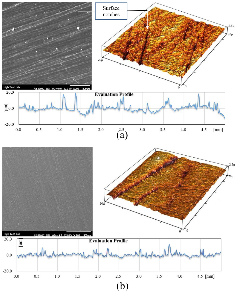
SEM image of surface profile and effect of working gap on surface roughness. Rotational speed: 1500, feed rate 0.05 mm/rev: (a) working gap = 0.5 mm, Ra = 0.53 µm and(b) working gap = 1 mm, Ra = 0.31 µm.
Circularity
The cross-sections of all circular parts are never fully circular, but they have some error tolerances. Circularity control is one of the geometrical tolerances, which shows how much the cross-section of a cylindrical object can be away from its ideal state. Figure 10 shows a sample of the graph obtained from a circularity measurement. The profile is magnified to make it easier to read. Circularity is a two-dimensional geometric tolerance that quantifies how much a feature can deviate from a perfect circle. In this research for each specimen 338 points were measured and the variation between the maximum and minimum diameters of the circle is calculated.
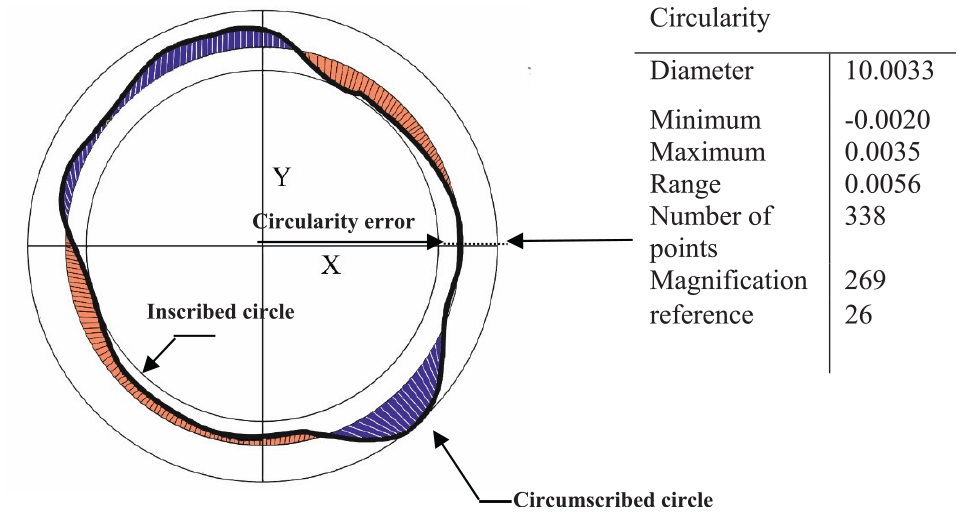
Polar graph of circularness measurement.
Figure 11 shows the equipment and measurement method of circularity. It should be noted that different points were tested randomly to achieve further precise results and the mean value was considered.
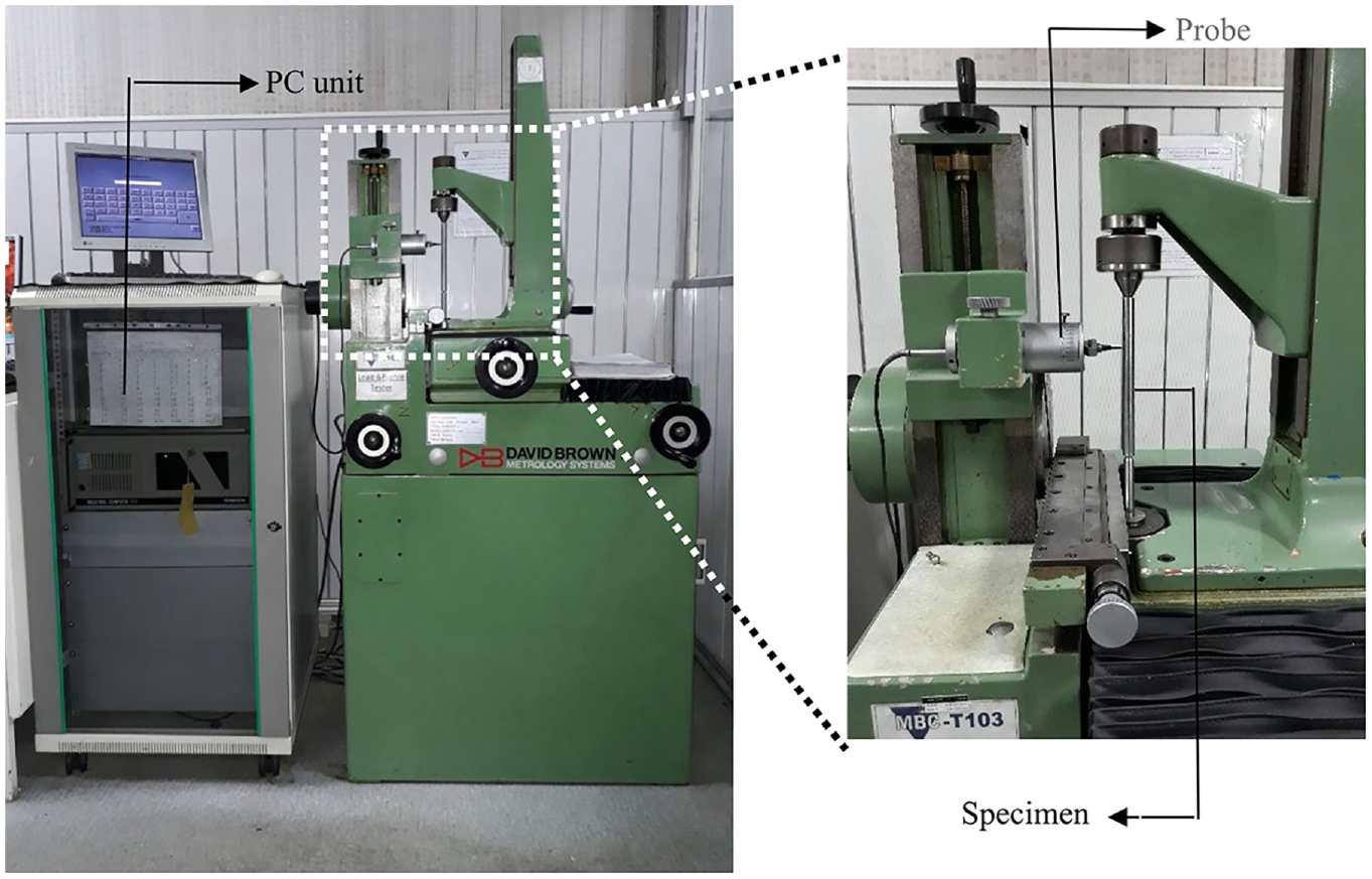
Circularity measurement equipment.
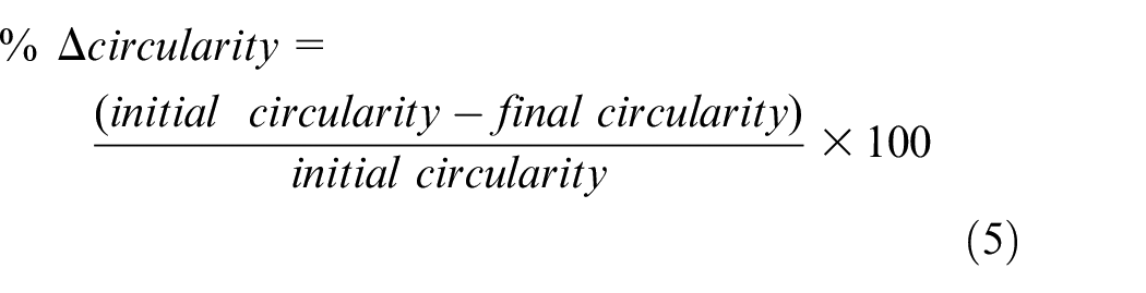
The diagram of Figure 12(a) shows the percentage change of circularity
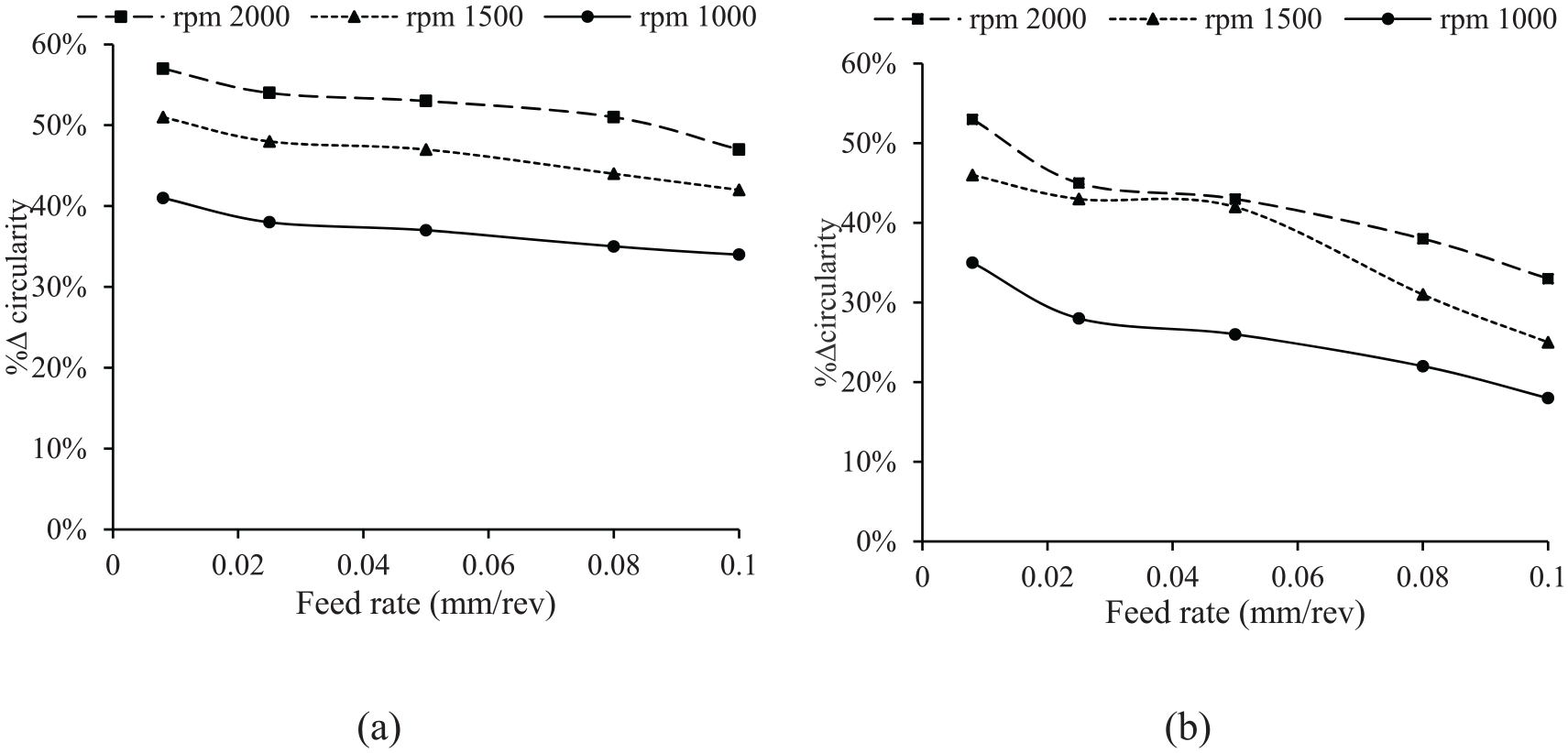
Effect of rotational speed and feed rate on circularity: (a) working gap = 1 mm and (b) working gap = 0.5 mm.
It can be concluded that by increasing rotational speed, the % Δ circularity improves and the closer circularity tolerance will be achieved in high rotational speeds. The diagram shows that the feed rate at high rotational speeds has a low impact on circularity, Therefore, the % Δ circularity changes are almost close to each other at the speed range of 1500–2000 rpm.
Figure 12(b) shows a relationship between the percentage change of circularity and rotational speed and feed rate at 0.5 mm working gap. The main difference between Figure 12(a) and (b) is in improving
Increase in the rotational speed above 1500 rpm did not show a significant change in
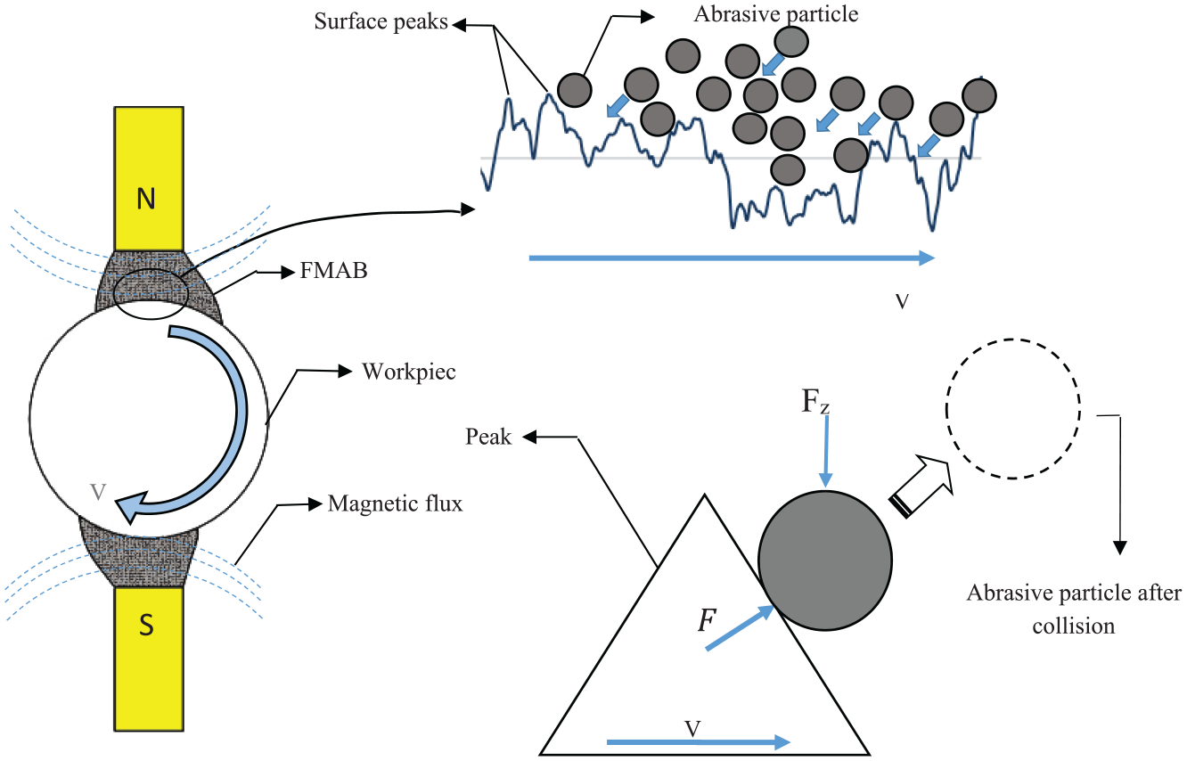
Schematic diagram of abrasive particles collision with specimen surface peaks.
Impulse force is evaluated by the following expressions:
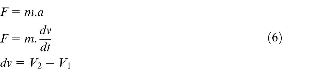
Where
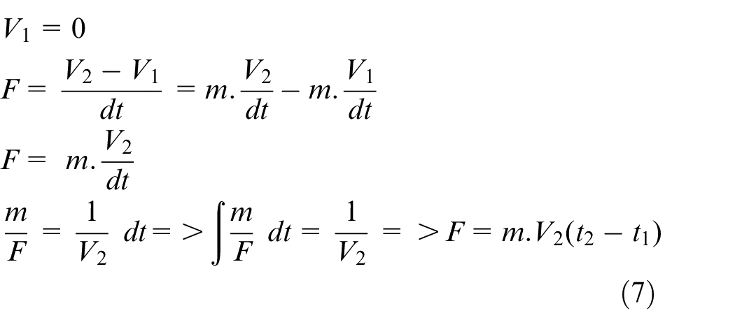
Where
Cylindricity
Cylindricity is another important geometric parameter in circular parts, which specifies how much a cylindrical part is far from its ideal state. A cylindrical tolerance zone is the volume between the two co-centered cylinders. The radial distance between two cylinders is equal to the cylindrical control tolerance. The controlled surface should be inside a volume that is defined by a tolerance zone (Figure 14). In fact, the cylindrical error is 3D tolerance, which examines circularity, as well as shaft straightness.
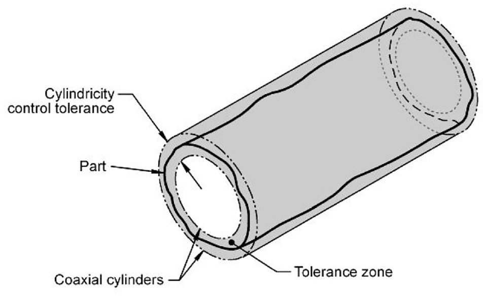
Cylindricity definition.
Figure 15 shows the equipment and measurement method of cylindricity. This research used a CMM with the precision of 0.001 mm for measuring cylindricity. It should be noted that more than 30 points of the workpiece have been touched in each test and the mean of cylindricity in each test was calculated and presented by a software system with an error smaller than 0.001 mm.
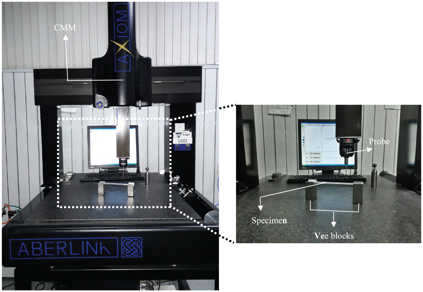
Measurement method of cylindricity.
Figure 16(a) and (b) show the percentages of change in cylindricity (% Δ cylindricity) with respect to the changes of rotational speed and feed rate in the two working gaps (1 and 0.5 mm). The percentage change of cylindricity can be calculated by equation (8).
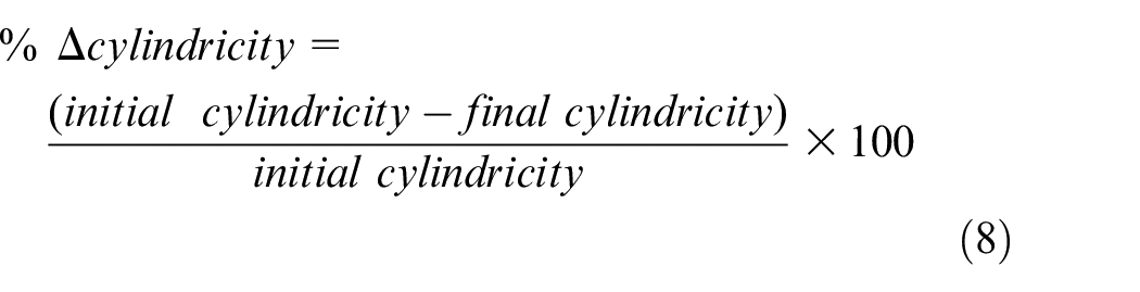
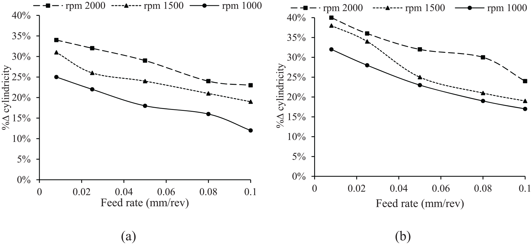
Effect of rotational speed and feed rate on cylindricity: (a) working gap = 0.5 mm and (b) working gap = 1 mm.
Examining the results shown in Figure 16, it can be concluded that the trend of cylindricity changes is the same as the trend of roughness and circularity variations, so that with increasing feed rate and decreasing rotational speed, the percentage change of cylindricity diminishes. It is due to that chips are removed for more convenience at higher rotational speeds, which may be a reason for dimensional accuracy improvement. According to Figure 16 by increasing the working gap cylindrical quality improved about 10% proximally. Because by reducing the working gap, flexible magnetic abrasive brush (FMAB) overspreads on workpieces (
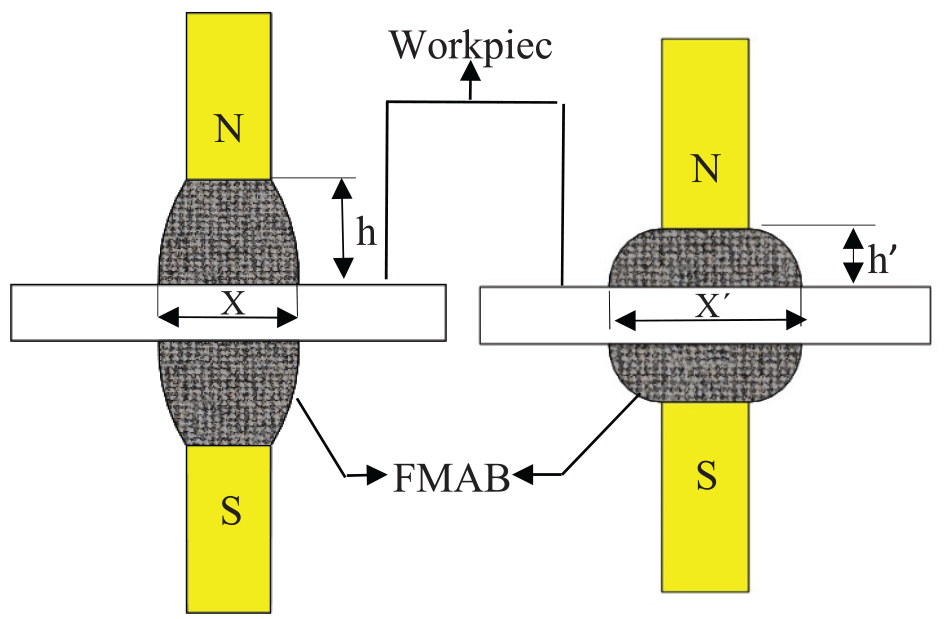
Effect of machining working gap on FMAB dimension.
Material removal rate (MRR)
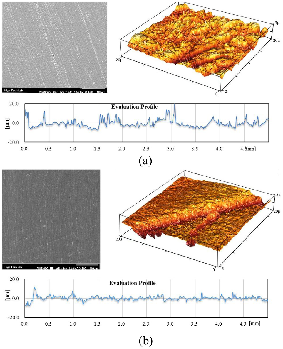
Figure 18 reports the MMR of MAF process. It shows that the rotational speed of specimen has a significant influence on MRR. The MRR increases with the increasing of the rotational speed of the specimen. They almost keep a linear relationship under given experimental condition. As long as the abrasive rotated smoothly, the material removal increased with increased rotation speed, generating a smooth surface. As reported in Figure 18 the MMR gradually decreased by increasing feed rate in MAF process. In the following, the effects of working gap on the MMR investigated in Figure 18(a) and (b) as is clear, the MRR increases with the decreasing of the working gap. This is because of that by increasing the working gap magnetic force decreased as result, MRR reduced. It is worth to be noted, by increasing feed rate (above 0.1 mm/rev) MRR significantly reduced. It is due to that abrasive particles do not have enough time to remove chips as well as, by increasing rotational speed above 2000 rpm because of centrifugal force abrasive particles spread out of abrasive zone and finishing process did not conducted. Together with, by increasing working gap (above 1 mm), the contact length of abrasive brush will be limited as result, chip removing will be very limited too. In addition to, by reducing the feed rate, rotational speed and working gap below than 0.08 mm/rev, 1000 rpm, and 0.5 mm no significant changes in MMR were observed. The morphological view of the workpiece surface before and after the MAF process is shown in Figure 19.
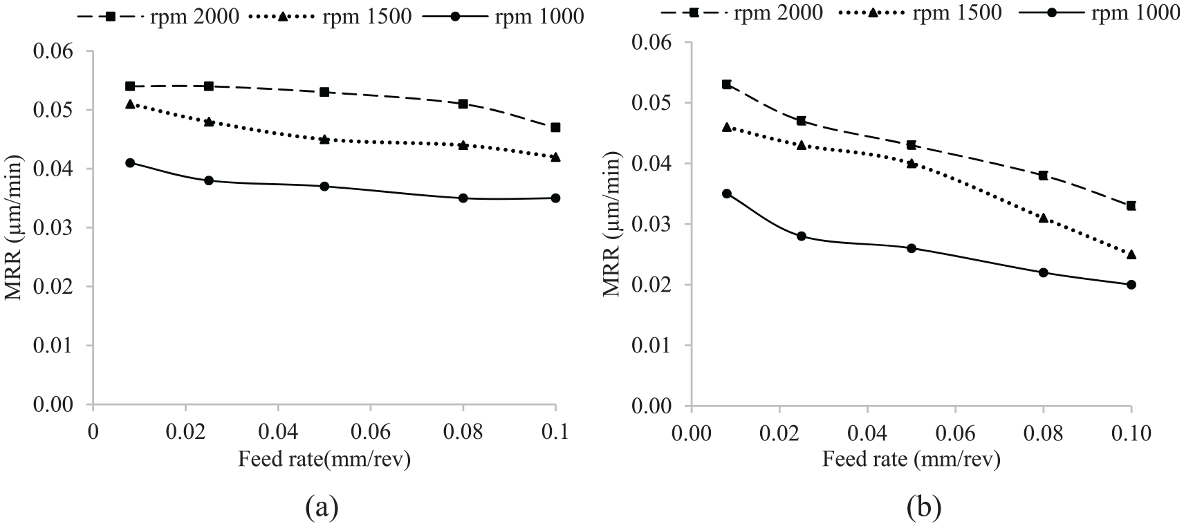
Effect of rotational speed and feed rate on MRR: (a) working gap = 0.5 mm and (b) working gap = 1 mm.
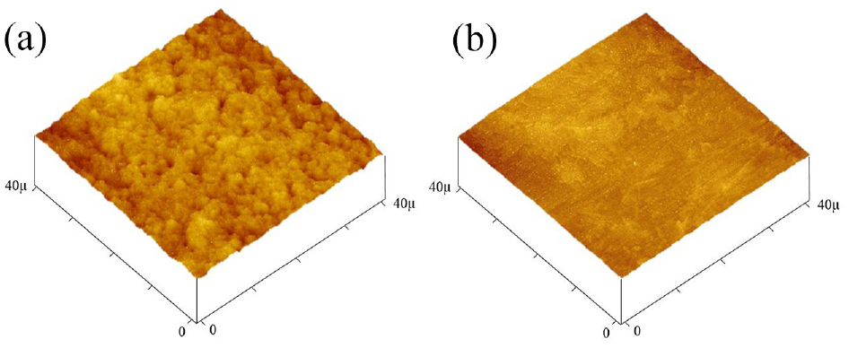
Morphological view before and after the MAF: (a) before MAF and (b) after MAF.
Conclusion
In this article, an Inconel 718 shaft was finished through the MAF process and effect of the main parameter of this process such as rotational speed, feed rate, and working gap on output parameters such as surface roughness and geometric parameters like circularity and cylindricity were studied. Controlling geometrical tolerance of workpiece in MAF process due to nano-chip removing system and multi cutting edge is absolutely challengeable. Based on the study, the following results are determined:
Surface roughness, circularity, and cylindricity are closely related, as similar output changes are seen by changing input parameters. It means that by controlling the values of one parameter, other parameters can be roughly predicted.
The impact of rotational speed on surface quality and the geometric parameters of circularity and cylindricity exceed other parameters, such as feed rate and working gap.
By increasing rotational speed, geometrical tolerance and surface roughness increased but after a certain speed, because of disarranging of FAMB and turbulence of the abrasive particles, it remained steady. Also, the size of FMAB plays an impressive role in geometrical tolerance, which is influenced by the working gap size. Therefore, by decreasing the working gap, the material removal process in elongation of the specimen conducted more uniformly.
Effect of feed rate on surface roughness and geometrical tolerances at lower rotational speeds is more severe compared to high rotational speeds.
By increasing working gap magnetic force reduced (equation (2)) as well as, increasing rotational speed leads to increasing cutting force and normal force (equation (6)) during the MAF processing stage.
Footnotes
Appendix
Acknowledgements
Authors would like to show their gratitude to Ms. Roza Ghadiri (Macquarie University) and Mr. Alex Ghadiri for providing language help and writing assistance in this paper.
Declaration of conflicting interests
The author(s) declared no potential conflicts of interest with respect to the research, authorship, and/or publication of this article.
Funding
The author(s) received no financial support for the research, authorship, and/or publication of this article.