
Abstract
The development of various nontraditional principles to finish the internal surfaces and passages is reviewed. In particular, attention is focused on three relatively mature finishing techniques: abrasive flow machining, internal magnetic abrasive finishing and fluidized bed machining. Their working principles, capabilities and limitations are evaluated accordingly. Finally, the significance of developing internal surface finishing capabilities and the vast potential ahead of this research field are highlighted.
Keywords
Introduction
Surface finish of the machined and manufactured components is an important requirement to ensure their durable performance. As compared to external surfaces, finishing and deburring of internal passages is less frequently addressed. Internal passages with poor surface finish could induce undesired boundary layer turbulence in the gas or fluid flowing inside them. 1 Turbine spray nozzles, waveguides and hydraulic manifolds are some examples of components that require high-precision internal surface finish. Due to geometrical limitations of traditional tools, processes such as lapping and polishing are unable to finish these passages.
Abrasive flow machining (AFM) emerged as a prominent solution to finish internal channels in the 1980s. 2 It involves passing pressurized semi-solid-laden media with abrasive particles through workpiece internal surfaces in repeated cycles. The abrasive particles interact with the internal surfaces, shearing off peaks and resulting in fine finishing. To date, it remains as one of the most preferred techniques in finishing inaccessible surfaces of a wide range of materials. 3 However, AFM has its limitations in finishing geometries such as blind holes. Furthermore, it has been proved difficult to achieve uniform finishing on channels with varied geometries or features such as protuberances.
On the other hand, the rising need to finish various kinds of internal passages has spurred researchers to look for other solutions. Numerous variants of AFM and other nontraditional finishing processes have since been introduced by researchers in the past two decades. The inspirations behind these new ideas are from diverse principles, ranging from magnetic, ultrasonic vibration to fluidized beds. Hence, there is a need to consolidate these studies and present a state-of-the-art review of their development, limitations and potential.
The established internal surface finishing processes to be reviewed and their variants are summarized in Figure 1. Each process’ working principle will be described, with its merits and constraints discussed. Finally, future research opportunities in view of the renewed significance in developing internal surface finishing capability will be highlighted.
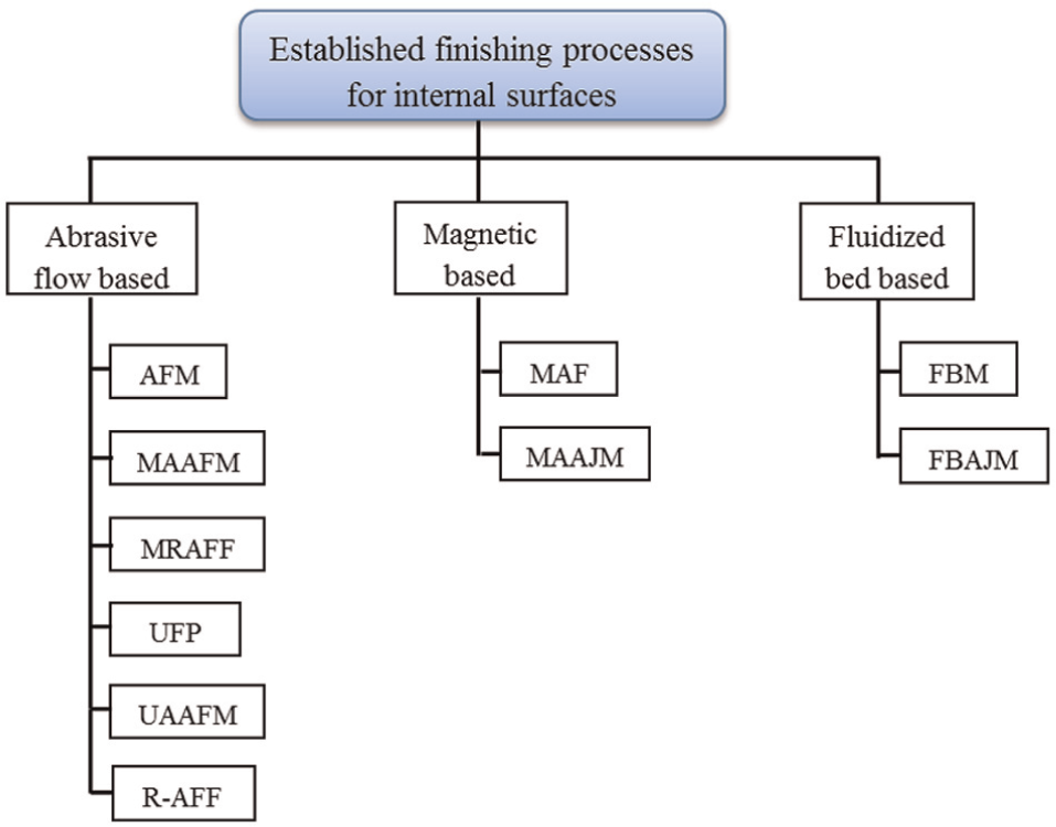
Classification of established internal surface finishing techniques.
AFM and its variants
AFM is one of the most established nontraditional finishing processes. It has been applied extensively to radius sharp edges and polish internal channels without detriment to original workpiece’s form accuracy. 4 Over the decades, process parameters have been investigated experimentally and automation has been achieved in commercial applications. Researchers have also come up with numerous variants, as presented in a comprehensive review by Cheema et al. 5
Process description and principle
A simple two-way AFM setup is illustrated in Figure 2. It consists of two opposing hydraulic cylinders, with the workpiece held in between by a fixture. When the abrasive media are being extruded under pressure from one cylinder to another, the workpiece internal passage forms a restricted area where the abrasive media flow. The flow would then be reversed, leading to one process cycle. Repeated process cycles improve the surface roughness of the internal contour.
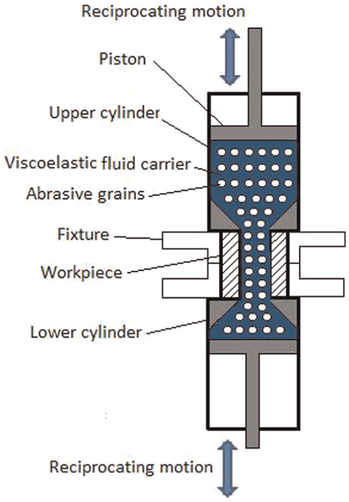
Schematic diagram of a basic AFM setup.
The principle behind AFM lies in the interaction of abrasive media with the workpiece internal surfaces. The abrasive media typically consist of a viscoelastic fluid carrier (polyborosiloxane), with hard abrasive particles (silicon carbide, alumina) distributed evenly within. It is analogous to a flexible abrasive stone that is able to navigate complex geometries and reach difficult-to-access areas. Extrusion of the highly viscous media under pressure results in radial force 6 acting toward the workpiece internal surface. Abrasive particles near the surface would then penetrate the workpiece and become active abrasive grains (Figure 3). The axial force induced by the media flow then provides the necessary energy in material removal. A layer of 1–10 µm is usually removed and the newly exposed layer forms a new surface with low roughness value.
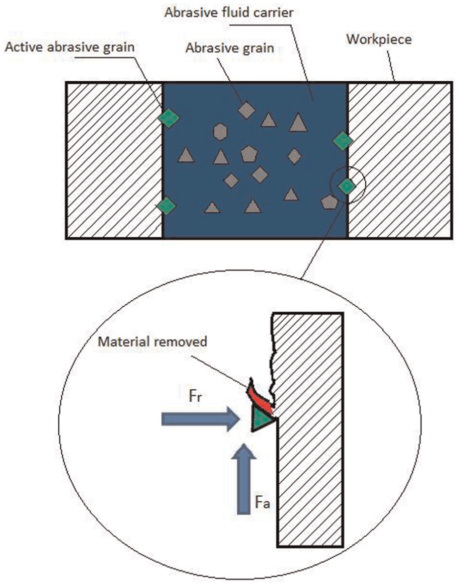
Schematic diagram of the action of a single active abrasive grain.
Mechanism of material removal
Two modes of abrasive wear, micro-ploughing and micro-cutting, have been identified as the mechanisms of removal in AFM. 7 In micro-ploughing, surface peaks are smeared and plastically deformed, resulting in “leveling out” of surface asperities. 8 No volume loss takes place in this mode of removal. Ridges are also formed adjacent to the grooves created by abrasive particles’ sliding path. On the other hand, in micro-cutting, abrasive particles act as single-point cutting tools, indenting and removing material in the form of microchips. In both forms of abrasive wear, scratches are characterized by continuous scratches. 7 Rotation of abrasive particles during sliding is limited; thus, AFM is similar to two-body abrasion in a traditional polishing process.
It is understood that the dominant mode of material removal is primarily dependent on the ductility of the workpiece material. 9 Singh et al. 10 reported metal smearing on ductile aluminum workpiece and pure abrasion cutting on brass workpiece. They further suggested that repeated cycles of micro-ploughing in ductile workpieces would lead to embrittlement and subsequent chipping of the ridges. To summarize, in a ductile workpiece, micro-ploughing occurs during initial cycles. Extensive plastic deformation then leads to material removal through microchip formation. In brittle materials, micro-cutting becomes the dominant mode.
Process parameters
The average surface roughness (Ra) is a well-known parameter to describe the surface finish achieved. Surface roughness improvement (ΔRa) and material removal rate (MRR) are the two essential performance parameters of an AFM process. Depending on the process parameters, percentage improvement in Ra as high as 90% could be achieved. 11 A large number of factors are known to affect the finishing performance, and numerous experimental investigations have been conducted. These factors are summarized into a cause-and-effect diagram in Figure 4.
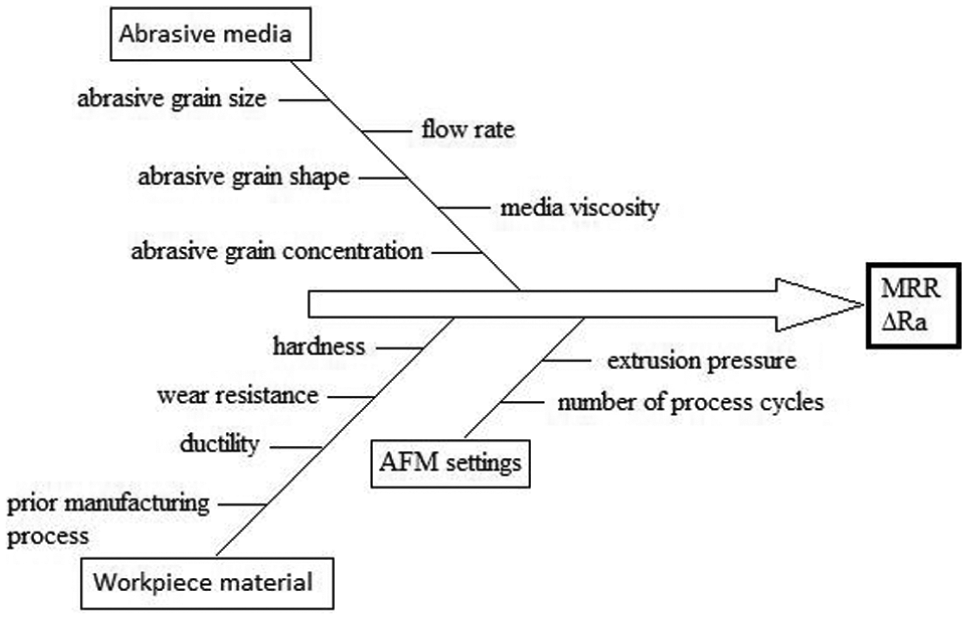
Cause-and-effect diagram for AFM.
Abrasive media
The abrasive media act as a flexible cutting tool, and thus its properties are crucial to the finishing performance. In commercial applications, polyborosiloxane and silicon are most often used as media carrier. Kar et al. 12 proposed rubber-based media (natural rubber, butyl rubber, ethylene propylene diene monomer rubber and styrene butadiene rubber (SBR) as an alternative and reported that SBR achieves the best ΔRa. As compared to commercial carriers, SBR also has lower viscosity. Viscosity determines the media flow rate, hence the surface pattern generated. 13 A less viscous media—with higher flow rate—would tend to result in more abrasion on the workpiece edges. Besides media carrier, abrasive grain properties including type, size, shape and its concentration in the polymer mix affect both MRR and ΔRa greatly. Silicon carbide is most commonly used, but other hard abrasive particles such as boron carbide, aluminum oxide and in certain applications diamond may also be adopted. 13 Abrasive grain typically ranges from 120 to 400 mesh sizes, with larger grains leading to an increase in the depth of penetration, thus higher MRR. Larger grains are suitable for workpiece with high initial surface roughness while smaller grains are used to achieve fine finishing. Jain and Adsul 14 reported that abrasive concentration in the polymer mix is the most influential factor among the process parameters investigated. By varying abrasive concentration from 50% to 80% by weight, they found that 80% abrasive concentration leads to both higher MRR and ΔRa. With higher abrasive concentration, more active abrasive grains take part in material removal.
Workpiece material
As abrasive wear is the mechanism of removal in AFM, hardness and wear resistance of a workpiece material are important to its MRR and ΔRa. Workpiece material with higher hardness leads to lower MRR and ΔRa. 15 Jain and Adsul 14 also reported lower material removal in brass than in softer aluminum under the same experimental conditions. This was attributed to the higher resistance to abrasion of brass than aluminum. Moreover, finishing performance is also dependent on prior machining processes. Loveless et al. 16 investigated the performance of AFM on samples machined by wire electrode discharge machining (WEDM), milling, grinding and turning, respectively. They concluded that ΔRa is the most significant in WEDM samples. This is due to the presence of thermal recast layers on WEDM-ed surfaces, rendering the surface hardness to be lower than in the bulk material.
AFM settings
Extrusion pressure and number of process cycles are the two machine variables in an AFM process. Extrusion pressure determines the radial and axial forces of the abrasive media on the workpiece internal passage, hence the abrasive grains’ indentation depth and subsequent material removal. 17 Sankar et al. 15 further suggested that higher extrusion pressure also increases medium velocity, leading to higher MRR. With sufficient extrusion pressure, each process cycle results in material removal and ΔRa. However, material removal and ΔRa were found to be the most significant during initial cycles.8,14 Jain et al. 18 attributed this to the presence of more surface peaks at initial cycles, which are easier to be removed. Surface roughness Ra could be reduced down to approximately 50 nm, beyond which subsequent cycles remove material but do not result in significant ΔRa.
Process capability and applications
AFM has been used extensively in aerospace, automobile and medical industry. 11 AFM is used mainly to debur internal passage of aircraft valve bodies and spools, 13 dies, automotive systems 19 and medical implants. AFM has also been a prominent solution to remove thermal recast layers left over by WEDM process. 20 Yan-Cherng et al. 21 also demonstrated AFM’s capability to finish micro-hole machined from WEDM effectively (Figure 5).
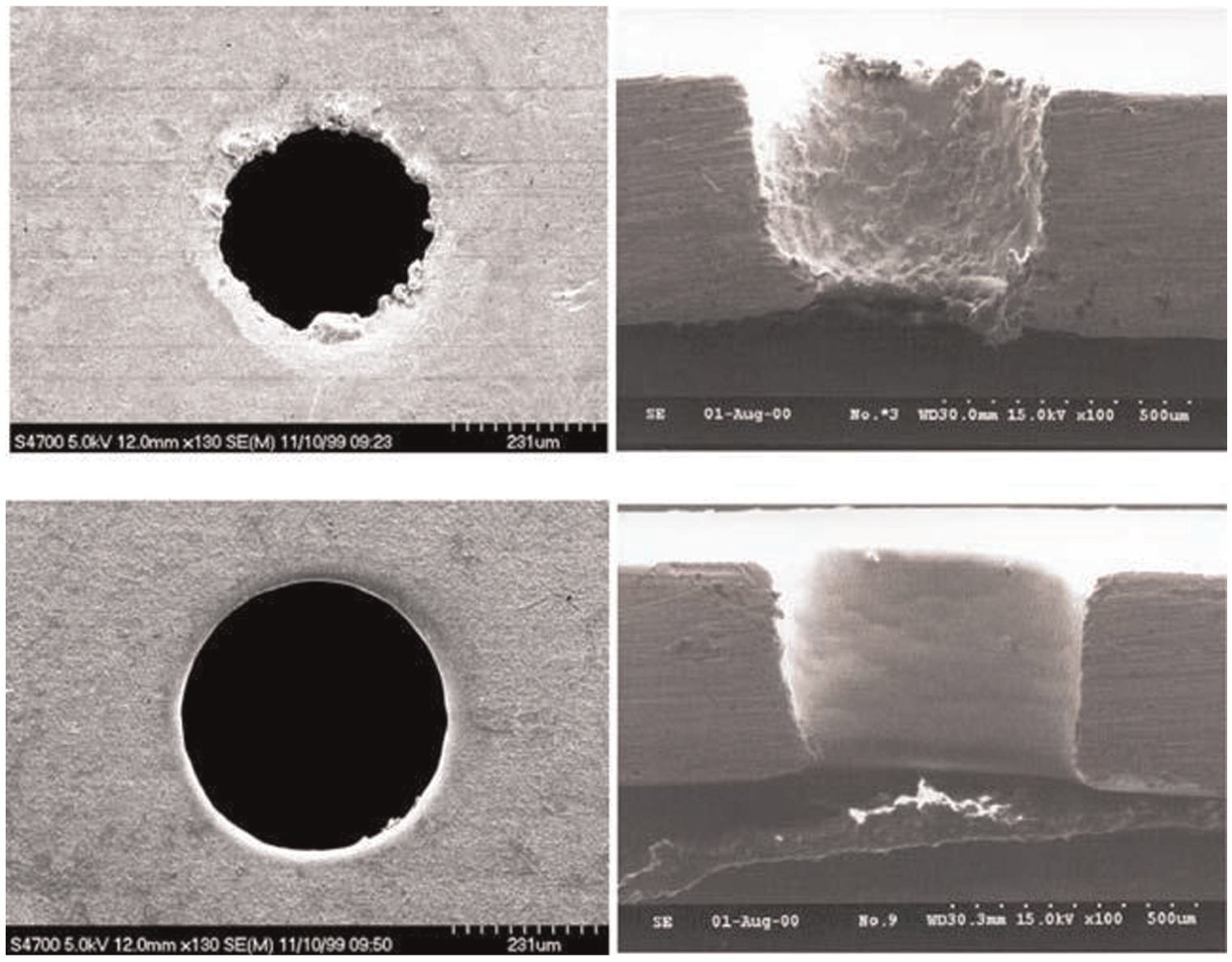
SEM image of a micro-hole as-machined by WEDM (above). After finishing by AFM (below).
Currently, AFM is the only viable commercial solution in components with complex internal passages or challenging geometry. One such example is finishing of micro-holes. The smallest scale of channel finished by AFM in the literature is found to be with a diameter of 0.26 mm. 22 The range of materials finished by AFM has also been expanded over the years. From traditional metals such as mold steel to plastic gears 23 and additively built resin-based material from stereolithography process, 24 AFM has achieved reasonable finishing performance. Recently, AFM was further shown to perform efficiently on advanced materials such as metal matrix composites (MMCs). 15
AFM variants
Aimed at increasing the number of active abrasive grains and providing additional finishing energy, AFM variants can be classified into three main groups: magnetic-based, ultrasonic-based and rotation-based.
Magnetic-based AFM
Magnetic-assisted abrasive flow machining (MAAFM) was first proposed by Singh and Shan. 25 The workpiece holding fixture was altered to accommodate the placement of electromagnets around the workpiece. Ferromagnetic abrasive particles were mixed in the modified abrasive media. The presence of a magnetic field results in sideway pull of the abrasive media, thus increasing the number of active abrasive grains. An enhancement of this principle is found in magnetorheological abrasive flow finishing (MRAFF). Jha and Jain 26 developed a magnetorheological fluid comprising carbonyl iron particles (CIPs) mixed with abrasive particles, dispersed in a nonmagnetic carrier such as silicone oil. On the application of external magnetic field, the rheological behavior of this smart fluid changes from nearly Newtonian to Bingham plastic due to the bonding strength of CIPs. This flexibility in rheological properties of the abrasive media allows possible control of finishing forces to suit different applications.
Ultrasonic-based AFM
The coupling of ultrasonic energy to energize abrasive flow was first introduced by Jones and Hull 27 in ultrasonic flow polishing (UFP). Pressurized abrasive flow passes through an ultrasonic tool before reaching the workpiece internal passage. This process is reported to have improved AFM’s capability in finishing blind cavities. More recently, ultrasonic vibration of 5–20 kHz was introduced to the workpiece through a piezoelectric actuator in ultrasonic-assisted abrasive flow machining (UAAFM). 28 Due to the workpiece vibration, abrasive grains were accelerated, resulting in higher interaction forces between the abrasive grains and workpiece internal surface. A better finishing performance than conventional AFM was reported.
Rotation-based
Rotational motion was introduced in AFM to alter abrasive particle pathway from axial to helical. This enhances MRR and ΔRa due to the longer pathway traversed by abrasive grains per process cycle. One of the methods to induce this helical motion includes inserting a center tooling such as rotating screw to guide abrasive media motion as in spiral polishing method. 29 Sankar et al. 30 developed a helical fluted drill in drill bit-guided abrasive flow finishing (DBG-AFF) and reported MRR and ΔRa to be almost doubled as compared to conventional AFM. Additionally, a workpiece can also be rotated, as in rotational abrasive flow finishing (R-AFF). 31 Besides altering the pathway of abrasive particles, R-AFF also results in an additional tangential force that leads to deeper abrasive penetration and better finishing performance.
The variant-enhanced AFM processes are largely at their nascent stage of development, intended to improve on conventional AFM’s processing capabilities. Increasing number of articles in this research area clearly suggests the rising demand for finishing of intricate internal surfaces and channels. Despite these variants largely improving the finishing efficiency of AFM, limitations exist. Magnetic-based AFM processes are known to work poorly on ferrous materials. In rotational-based processes, additional center tooling required imposes strict geometrical restrictions. Furthermore, the processes are only feasible on workpieces with rotational symmetry.
Recent developments in AFM
As rheological properties of the abrasive media are crucial, researchers have been looking for new-generation abrasive media to achieve better finishing performance. Kar et al. 32 found that butyl rubber media mixed with naphthenic oil and silicon carbide exhibits reasonable finishing performance. Wang and Weng 33 also suggested a similar rubber-based media, silicon rubber, as a cheaper alternative to polyborosiloxane. Lunn et al. 34 filed a patent and claimed that their elastomeric polymer media leads to more uniform abrasive machining due to superior rheological properties. More recently, Sooraj and Radhakrishnan 35 proposed a new type of “elastic abrasive,” where 3-mm polymer beads were used as elastomeric medium to carry embedded abrasive grains. They reported a finer finishing of 20–30 nm Ra using this new medium.
A recent trend also sees increasing efforts in modeling an AFM process. Computational fluid dynamics (CFD) is gaining prominence as the simulation tool in understanding basic flow mechanism behind AFM. Researchers are particularly interested about media flow in complex geometrical conditions such as chain holes 36 and tubes with ellipsoidal cross section. 37 Furthermore, AFM variants have also been explored in recent simulation studies. Das et al. 38 studied the flow of magnetorheological fluid to calculate the stresses developed during polishing. Gudipadu et al. 39 modeled the media flow in a UAAFM setup and reported that higher wall shear from the simulation results could explain UAAFM’s better finishing rate over conventional AFM. In another study, Chen and Cheng 40 simulated abrasive helical motion in finishing a polygon hole and validated the simulation results with the experiments. CFD has the potential in reducing the cost of conducting experimental investigations and making accurate predictions in finishing performance of AFM. However, in most cases, experimental validations to ensure the accuracy and applicability of the results are still lacking.
Process limitations
Despite significant research efforts and progress made in AFM, numerous limitations still exist. Geometries such as blind holes remain difficult to be finished effectively by AFM. AFM’s media are also governed by the fluid flow properties, leading to difficulty in exerting uniform finishing forces on complex internal surfaces. Preferential flow over more restricted areas results in non-uniform finishes. Furthermore, abrasive particle embedment onto the workpiece surface had been reported by various researchers, thereby raising contamination issues. This could be undesirable in parts where high material purity of the component is required.
Internal magnetic abrasive finishing
Magnetic abrasive finishing (MAF) is a high-precision nontraditional finishing process in which the finishing forces are controlled by a magnetic field. Magnetic abrasive particles supplied to a workpiece are influenced by magnetic poles, thus forming a flexible magnetic abrasive brush. 41 Much development of this process took place in Japan in the late-1980s and 1990s. It was first proposed as an external finishing process for cylindrical objects by Shinmura et al. 42 Research efforts have since established understanding of the process behaviour 43 and surface pattern generated. 44 In 1990s, a modification saw its unique application in finishing the inner surface of a clean gas bomb. 45 Following which, MAF’s capability to finish the internal surfaces has been explored and demonstrated on the tubes of various sizes and materials.
Process description and principle
A fundamental single pole system setup of an MAF process for the internal surface is shown in Figure 6. It consists of a magnetic pole system positioned outside the component. Magnetic abrasives are fed into the channel to be finished. When current is supplied to the coils around the magnetic yoke, magnetic abrasive particles conglomerate according to magnetic field distribution at the finishing zone, acting as a flexible brush. The workpiece is usually fixed to a chuck with spindle to induce high-speed rotation. The magnetic yoke could also be rotated in an opposite direction to workpiece rotation as in a rotational pole system. In some setups, the workpiece is also vibrated axially at amplitude of 10–50 mm and frequency between 5 and 20 Hz. All these movements aim to generate relative motion and abrasion between the magnetic abrasive particles and the workpiece internal surface. With repeated revolutions, a smooth inner surface would be generated. To prevent excessive frictional force, lubricating fluid such as oil could also be fed into the passage during finishing, in what is described as a wet process.
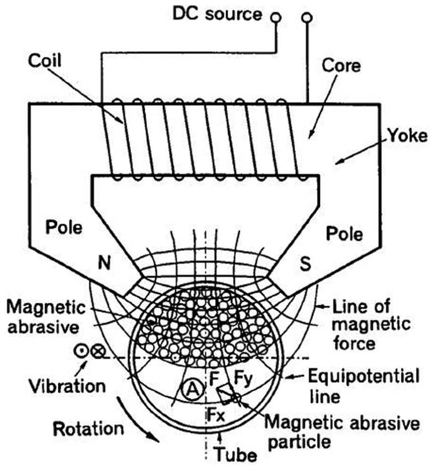
Schematic diagram of MAF for internal surfaces. 45
The magnetic abrasives’ behavior in the presence of magnetic field forms the fundamental principle behind this finishing technique. The commonly used magnetic abrasive particles are conglomerates that contain large-sized particles with high magnetic susceptibility (iron particles) sintered with smaller hard nonmagnetic abrasive particles such as aluminum oxide. On the application of magnetic field, magnetic forces acting on these magnetic particles exert pressure on the inner face of a channel. Under pressure, the cutting edges of hard abrasive particles penetrate onto the workpiece surface. Subsequent rotation of workpiece or pole system at high speed thus induces relative motion between the workpiece and abrasive particles. At desirable working conditions, magnetic conglomerates follow rotation closely, which makes it similar to fixed abrasive polishing with controllable contact force. The material is removed in the form of fine abrasion with increasing machining time.
Process parameters
As with other finishing processes, ΔRa and MRR are used to evaluate the performance of MAF for the internal surfaces. Although detailed experimental studies are scant, most factors affecting the processing outcome have been identified. Figure 7 groups these factors into three broad categories: magnetic abrasive mix, finishing unit and workpiece material, respectively. Among these, factors that directly influence magnetic abrasive mix behavior and its relative motion with workpiece inner surfaces are known to have the most significant effect on ΔRa and MRR.
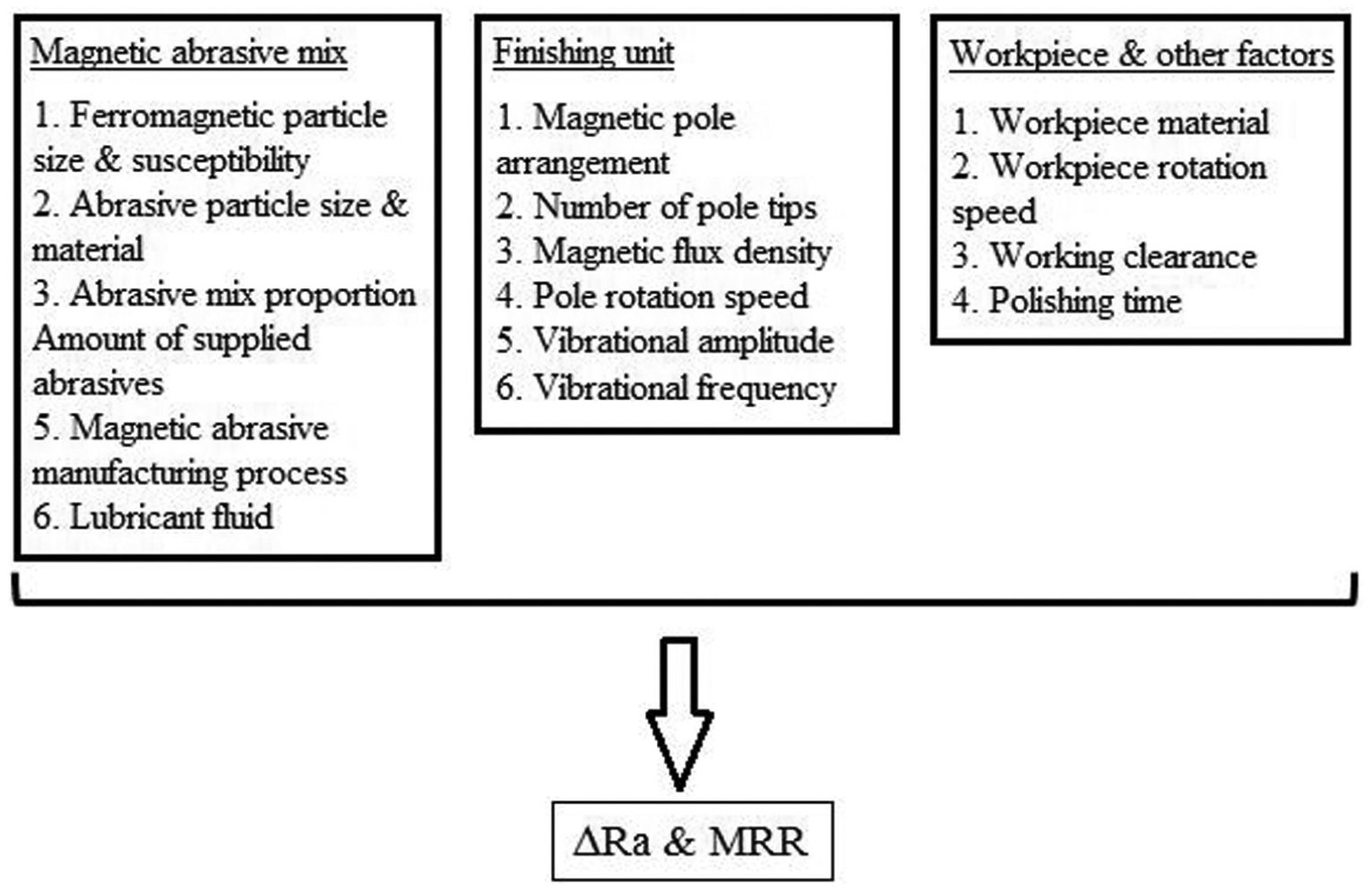
Factors affecting an internal MAF process.
Magnetic abrasive mix
The modern mixed-type magnetic abrasive was invented to obtain a balance between magnetic susceptibility and abrasion properties of magnetic abrasive conglomerates. 45 Large ferromagnetic particles (100–500 µm) are responsible to produce magnetic force and finishing pressure; while hard abrasive particles (5–20 µm) are responsible for abrading workpiece surface and removing material. In general, as ferromagnetic particle size increases, finishing force per particle increases, thus resulting in increasing MRR. However, beyond particle size of 330 µm, excessive material removal occurs, which negatively impacts minimum Ra achievable. 45 On the other hand, smaller abrasive particle size leads to more particles being sintered on each ferromagnetic particle. The magnetic force is thus distributed over more particles, resulting in smaller depth of penetration and finishing force. This was identified as being suitable for ultra-fine finishing applications. 46
The effects of abrasive mix proportion and amount of supplied abrasives on finishing characteristics have been investigated by various researchers. Optimum abrasive mix ratio of abrasive particles against ferrous particles is approximately 20%–35%. 47 For the amount of supplied abrasives, care must be taken to avoid abrasive oversupply. Excessive amount results in magnetic abrasives unable to follow magnetic pole rotation, causing abrasive jumbling on the inner surfaces (Figure 8). 48 If this occurs, random scratches and abrasive marks would be present on the resulting surface. In addition, lubricant addition was found to result in much higher material removal than dry condition. 49 Lubricating fluid was found to be optimum at approximately 7 wt%, beyond which the frictional force between abrasive particles and workpiece surface would be too small to have any effective material removal. 50
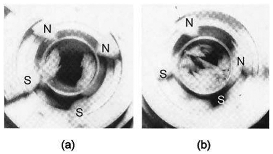
Magnetic abrasive behavior: (a) smooth rotation and (b) irregular jumbling.
Finishing unit
The finishing unit consists of magnetic pole, tip, yoke and the motion systems that control its rotation and axial vibration. Magnetic pole arrangement and pole number variations have been explored. 51 Figure 9(a) shows a few possible pole arrangements which vary from a conventional single north (N)–south (S) pole system. 49 The effectiveness of pole arrangement is found to be closely related to the resulting finishing area and pressing force of magnetic abrasive particles. In another study, Kang and Yamaguchi 52 proposed a multiple pole tip system as shown in Figure 9(b) to increase the finishing area, thus efficiency.
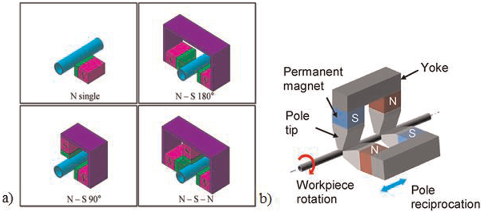
(a) Clockwise from top-left: single pole tip, 180° N–S, N–S–N pole tips, 90° N–S and (b) Multiple pole tips on a single yoke.
It is understood that the stronger the magnetic flux density, the higher the finishing force acting on the workpiece internal surface. Moreover, higher pole rotation speed and vibration frequency also improve relative motion between the abrasive and the workpiece. However, sufficient magnetic flux density is needed to sustain smooth motion of the magnetic abrasive conglomerates at all times. Otherwise, irregular jumbling of abrasive (Figure 8) would occur, resulting in inefficient finishing.
Workpiece and other factors
As MAF is fundamentally an abrasion process, workpiece’s relative hardness to abrasive particles determines the depth of cut of the abrasive cutting edges. The working clearance between the magnetic yoke and the workpiece also affects the magnetic field strength at the finishing area directly. This effect is especially crucial at finishing of bent tubes whereby different finishing forces are needed at the inner and outer radii areas. 53 Finally, ΔRa is achieved mostly within the first few minutes of the process, beyond which only material removal takes place and surface roughness could no longer be improved.
Process capability and applications
MAF offers mirror-like surface finishing capabilities as roughness could be reduced down to 10 nm Ra. It is a high-precision process whereby form accuracy is not adversely affected. The concept of internal MAF was first demonstrated on difficult-to-access area of the internal surface of a clean gas bomb (Figure 10). 45 Non-ferromagnetic tubes in gas and liquid piping systems have been frequently adopted as test pieces. Vacuum tubes and waveguides have also been identified as possible applications due to their requirement of high-precision finish. In terms of scale of workpiece that can be processed, the minimum scale is limited by the ability to feed magnetic abrasive mix into the channel. From the available literature, the internal surfaces of capillary tubes as small as 0.4 mm diameter, commonly seen in medical and chemical industry, were shown to be finished efficiently by MAF process. 54 Studies had also been carried out to modify the process for bent and complex tubes to be finished uniformly. 55 In some studies, a robot was integrated to the finishing unit for process automation. 41
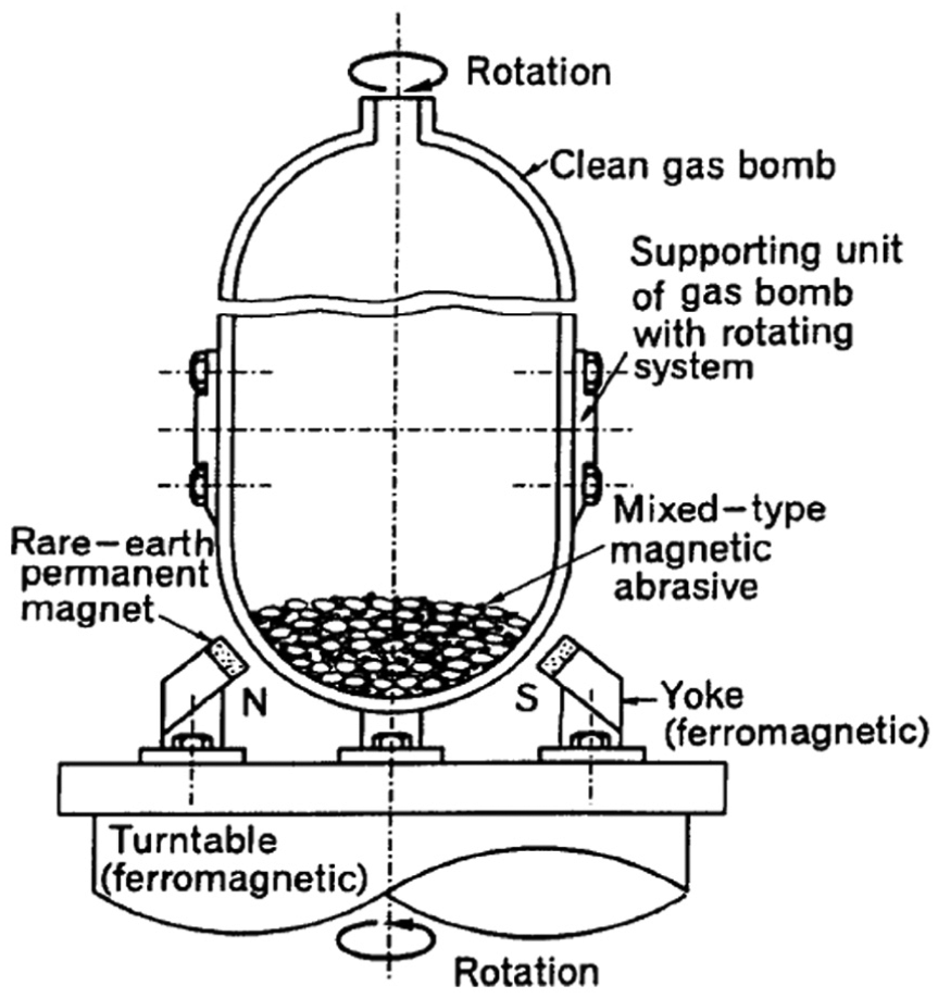
Schematic diagram of MAF application on internal surface of a clean gas bomb. 45
MAF variants
Magnetic abrasive jet machining
Magnetic abrasive jet machining (MAJM) (Figure 11) is a process that combines both MAF and AJM principle. 56 Electromagnets are positioned outside the component as in a conventional MAF process. Magnetic abrasive particles are then jetted by compressed air into the workpiece channel at high velocity. In the presence of magnetic field, these particles are deflected, which in turn impact the inner surface of the workpiece at various angles. Jet velocity and magnetic flux density are the most important factors that determine the impact force and angle of abrasive particles. Controlled removal of the material can result in finishing.
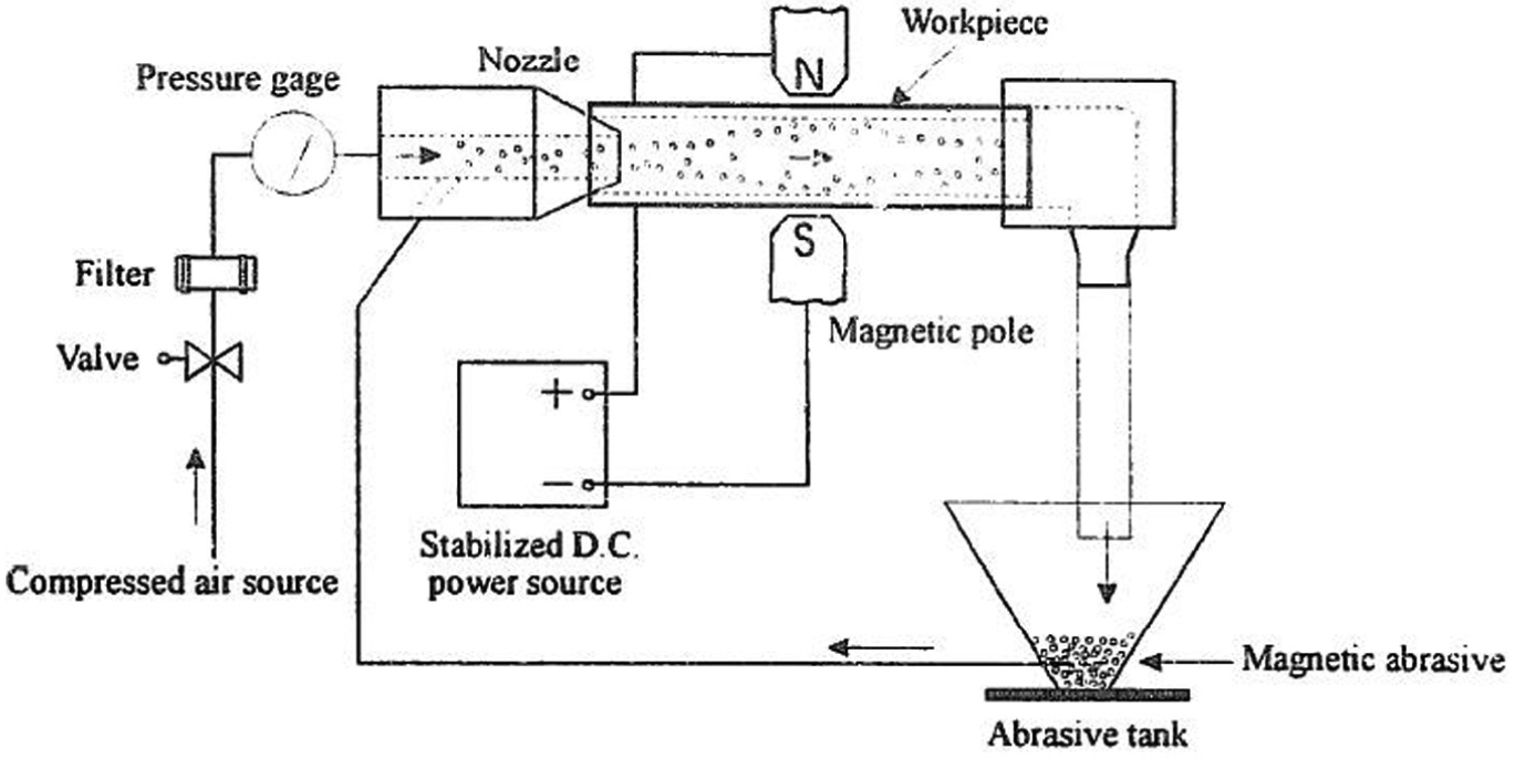
Schematic diagram of a MAJM setup.
MAJM could provide larger material removal and finishing force than conventional MAF due to the high velocity, thus impact forces of abrasive particles. However, application is limited to simple straight geometries. Further development of this technique could focus on understanding the effect of abrasive impact angle on material removal. Methods to manipulate abrasive particle path could also be explored.
Process limitations
Despite the promise of producing mirror-like surface, MAF’s biggest limitation lies in the restriction on the materials that are suitable to be processed. Surface finishing is negligible on ferromagnetic materials such as nickel and cobalt alloy. This is due to the workpiece being magnetized in the presence of magnetic field, thus attracting magnetic abrasive particles to it strongly. Rotation of the workpiece is thus unable to generate any relative motion between magnetic abrasive particles and workpiece surface. Furthermore, in an internal MAF process, components with rotational symmetry are favorable. Complicated internal features such as fins and protuberances would render MAF inefficient as magnetic abrasive particles are unable to navigate around these features.
However, these limitations could be stretched by further research effort. More experimental studies are needed to extend understanding and fully realize the potential of this finishing process. Among these, the potential of ferromagnetic particles other than iron to be used in the magnetic abrasive mix can be explored. Factors such as workpiece hardness and ductility, magnetic pole variation or a combination of various factors can be studied. Finally, more process variants, such as adopting chemical principle into MAF, can potentially widen its applications. 57
Fluidized bed machining
Fluidized bed machining (FBM) is a recently developed nontraditional process utilizing fluidized bed hydrodynamics for finishing. Fluidized bed is formed when a bed of solid abrasive particles is manipulated under fluid flow such that the particles behave like a liquid. Due to the fluid-like behavior, it has been demonstrated that finishing of both the external and internal surfaces is achievable. 58 In later developments, fluidized bed abrasive jet machining (FB-AJM) was proposed specifically for internal surface finishing applications. 59
Process description
A fundamental FBM setup is illustrated in Figure 12. It consists of a fluidized bed column with a homogenization section at the base and abrasive particles driven by air flux across the column, with the workpiece held in a fixed location inside the fluidized bed. As flow rate increases such that fluid bubbles are generated within the abrasive bed, abrasive particles are projected by the fluid and impacted onto the surface of the workpiece. The abrasive media have transportational properties of a fluid and hence are able to reach complex and inaccessible areas. Impingement of abrasive cutting edges results in normal and tangential forces being generated on the workpiece surface, causing indentation and material removal respectively. Repeated impingement results in the improvement of surface roughness on both the external and internal surfaces.
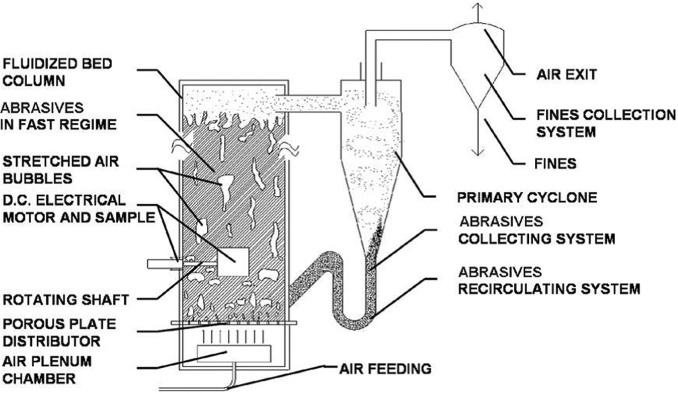
Schematic diagram of a FBM setup.
FB-AJM, on the other hand, combines both FBM and AJM principles. 61 Two fluidized beds are integrated with an abrasive jet system, as shown in Figure 13. Abrasives are sucked from one of the fluidized beds and fed through the workpiece to the other bed. As abrasives move in high speed, surface peaks within the passages are impacted and removed. The use of fluidized beds ensures the establishment of a fast transport regime of abrasives inside the workpiece and the reversibility of the machining process.
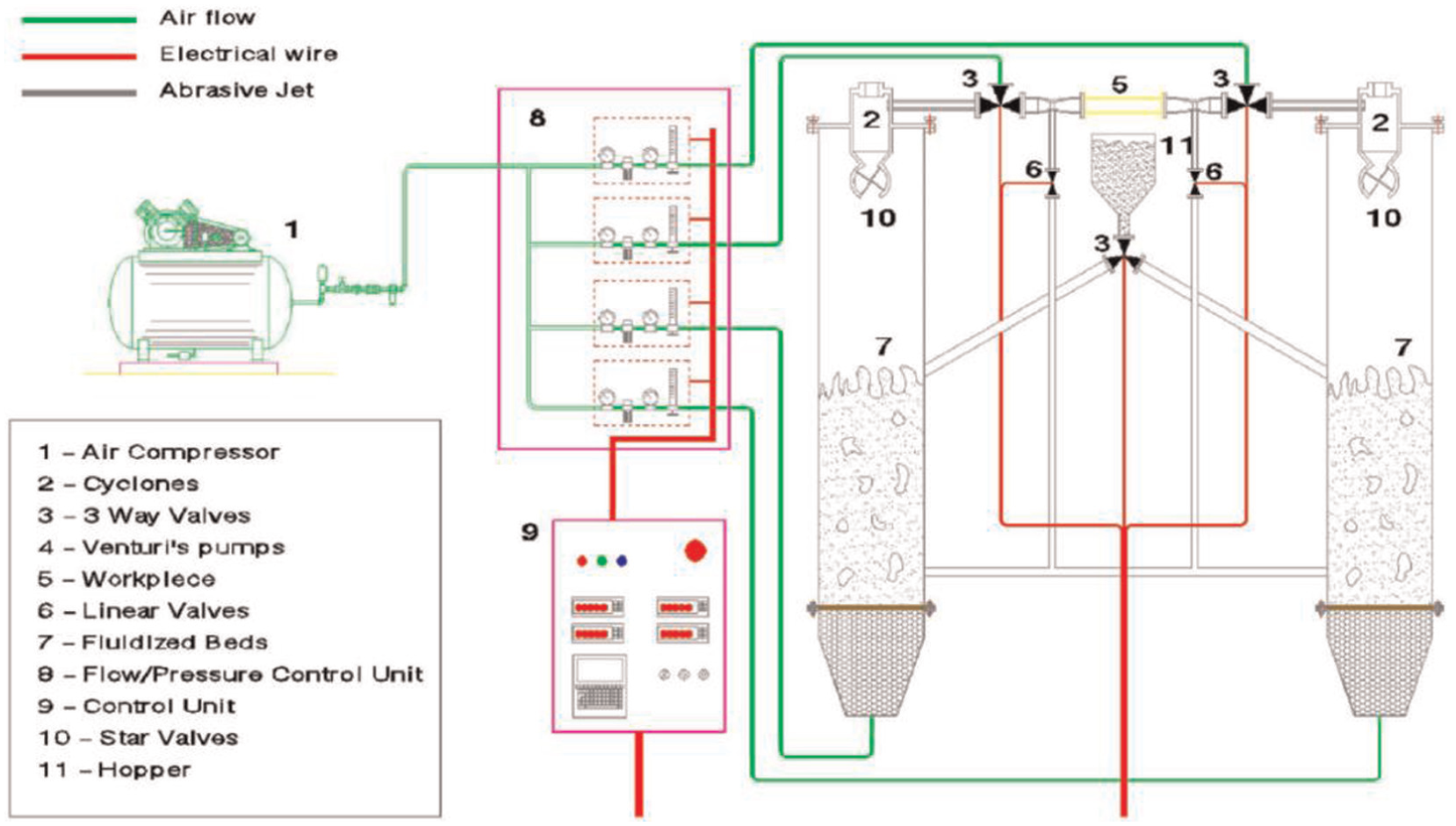
Schematic diagram of a FB-AJM setup.
Mechanism of material removal
Both FBM and FB-AJM are loose-abrasive processes. Fluidized bed accelerates abrasive particles to high speed and impact a workpiece surface at various angles. As such, the mechanism of removal is dependent on the speed and angle at which abrasive particles strike the surface. 60 Generally, for an abrasive particle impinging a surface at a low speed and angle, it results in rolling with no significant material removal. Higher speed impacts of abrasives result in deeper penetration of cutting edges into the workpiece. In addition to having longer interaction with the workpiece surface, these abrasives tend to slide across the workpiece surface and remove more material.
Process parameters and characterization
In both FBM and FB-AJM, fluidization characteristic is the most important factor affecting the process capability. Additionally, as other abrasive-based processes, abrasive and workpiece properties also play a role in finishing efficiency.
Fluidization regimes
The fluidization regime is influenced by the flow rate supplied to the fluidization column. At the minimum fluidization regime (Figure 14(b)), the weight of the abrasives counterbalances the hydrodynamic push exerted by the flow rate and the abrasive beds tend to easily transit between a fixed bed and a bubbling bed. With a slight increase in the flow rate, the abrasive bed reaches its bubbling regime (Figure 14(c)). The impact speed is typically very low (well below 1 m/s) in this regime. As the flow rate increases, the bubbles increase in dimensions (Figure 14(d) and (e)) until the abrasive bed reaches a pneumatic regime (Figure 14(f)) where the bubbles disappear. In the pneumatic regime, impact speed is often higher than 10 m/s and sometimes as fast as 50 m/s. High-impact speed of abrasives results in higher MRR and also higher indentation depths, giving rise to invariant but inaccurate surface finishes. In comparison, low-impact speeds lead to slower changes in surface morphology as indentations generated are of shallower depth.
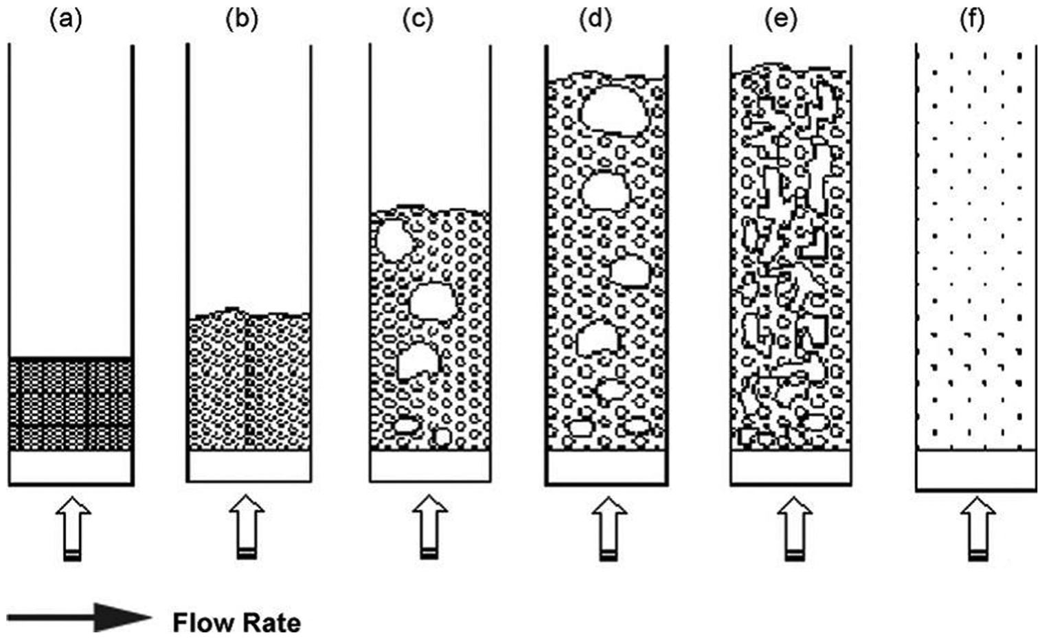
Fluidized bed regimes at different flow rates (a) fixed bed regime; (b) minimum fluidization; (c) bubbling bed regime; (d) slugging bed regime; (e) turbulent bed regime and (f) pneumatic bed regime.
Process capability and applications
FBM and FB-AJM offer fine finishing capabilities as the internal surfaces can be finished down to 0.4 µm Ra and lower, regardless of initial surface morphology. At the current stage of development, there are limited commercial applications of this technology. In the literature, surface improvements have been demonstrated on narrow and long tubular test pieces of aluminum 62 and stainless steel. 60 FB-AJM has also been shown to finish difficult-to-machine nickel alloys down to 0.15 µm. 61
Process limitations
A key limitation of FBM is the presence of debris remaining on the machined surfaces. Embedding of abrasive splinters onto the machined surfaces was observed for soft and ductile workpieces such as aluminum and polyvinyl chloride (PVC). The origin of the splinters is due to the fragmentation of abrasive particles during high-speed impacts. 63 Furthermore, in FBM, surface improvement on the internal surface is significantly less than the external surface. 58 For FB-AJM, the integration of abrasive jet principles renders the process unable to finish bent passages.
Summary
The summary of the established nontraditional internal surface finishing processes is given in Table 1.
Summary of established nontraditional internal surface finishing processes.
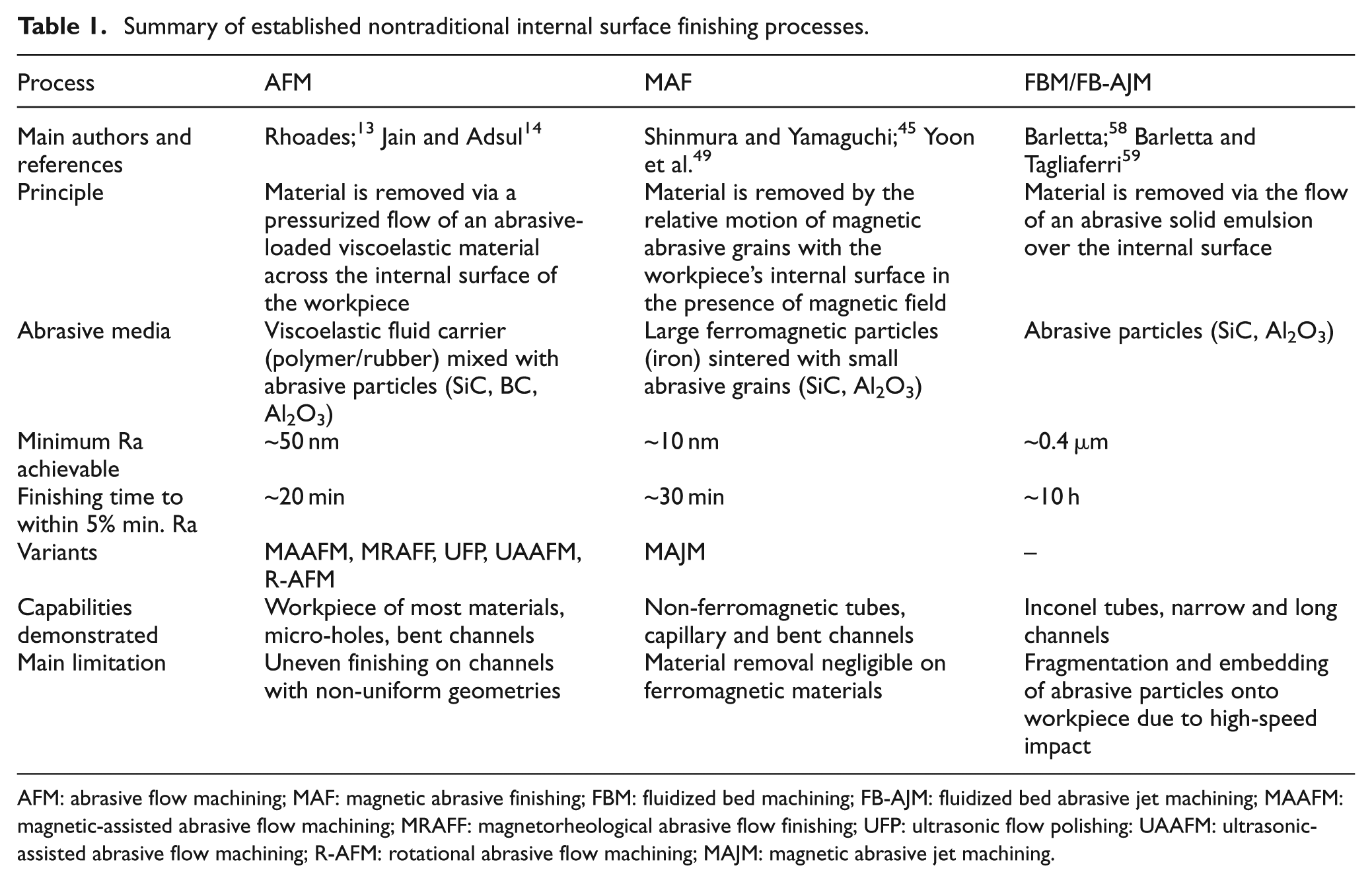
AFM: abrasive flow machining; MAF: magnetic abrasive finishing; FBM: fluidized bed machining; FB-AJM: fluidized bed abrasive jet machining; MAAFM: magnetic-assisted abrasive flow machining; MRAFF: magnetorheological abrasive flow finishing; UFP: ultrasonic flow polishing: UAAFM: ultrasonic-assisted abrasive flow machining; R-AFM: rotational abrasive flow machining; MAJM: magnetic abrasive jet machining.
Research potential
Despite much advancement in the development of internal surface finishing capabilities over the past decades, bountiful opportunities still exist for researchers. Research opportunities are present in two major areas. First, possible adaptation of advanced principles into development of new internal surface finishing techniques could be explored. Second, with the rise in prominence of additive manufacturing (AM), efforts could be directed to look for efficient internal surface finishing solutions for AM components.
Adoption of principles from existing advanced finishing processes
Current internal surface finishing solutions are largely based on abrasive polishing principle, which has a limitation in minimum Ra achievable. For nanoscale surface finish, advanced non-abrasive finishing processes such as electro-polishing and laser polishing are preferred. In electro-polishing, a workpiece is immersed in an electrolytic bath, acting as an anode. When direct current is passed through a cathode tool, anode dissolution, based on Faraday’s law of electrolysis, takes place. 64 “Anodic leveling” ensures that surface peaks are preferentially dissolved and very fine surface finish (<0.1 µm) can be achieved. 65 Laser polishing, on the other hand, is based on local surface melting and redistribution of surface asperities. 66 With alterations in energy density and other laser parameters, the surfaces of very high initial roughness can be smoothened significantly. 67
However, at the current state, these promising processes mostly found applications on external surface finishing only. Efforts to adapt these principles for internal surface finishing are scant. Hocheng and Pa 68 first investigated electro-polishing of internal holes by feeding electrodes through the passage. They reported minimum roughness of approximately 0.8 µm Ra. More recently, Mahdavinejad and Hatami 69 adopted electrochemical principles to finish internal surface of a gun barrel. A cathode tool that closely traces the internal contour of the gun barrel was designed. With electrolyte flowing through the gun barrel, and barrel internal surface acting as an anode; nanoscale material removal took place. A final surface finish of 0.12 µm Ra was achieved. With additional tooling considerations, these advanced principles could be adapted for internal surface finishing.
Internal surface finishing for AM components
Developing internal surface finishing capabilities has a renewed significance due to the rising prominence of AM technology. In AM, a laser or electron beam acts as the heat source to melt metal powders selectively. Components are built layer-by-layer according to a computer-aided design (CAD) prototype. AM offers designers limitless possibility in component and structural design. However, a major disadvantage arises in poor surface finish of these components (Ra ∼ 10 µm). 70 Partially melted powders and pores inherent of the AM process contributed to the poor roughness. Post-processing finishing is often required to improve surface integrity of these components. While abrasive blasting, laser polishing, 71 chemical polishing 72 and robotic finishing 73 have been developed to polish the external surfaces of AM components, internal surface finishing solutions remain scant and in need of development.
In one of the pioneering studies targeted at finishing internal surface of AM component, Furumoto et al. 74 made use of high-speed water-based abrasive slurry flow. Application of differential pressure between channel’s entry and exit induced high-speed flow of the abrasive slurry. This enabled abrasive grains to collide onto internal surface peaks and asperities. Most partially melted and adhered powders left over from the AM process were found to be removed after approximately 500 s of finishing time. In a follow-up study, Furumoto et al. 75 demonstrated the ability of this process to finish internal channels with face protuberance.
Due to the unique surface texture and high initial surface roughness of AM components, large material removal is required to improve its surface roughness. An additional challenge is the often complex and difficult-to-access internal surfaces of AM components. Some examples of these AM components are illustrated as simple CAD drawings in Figure 15. Existing finishing techniques lack either in internal surface accessibility or material removal capability. Any research breakthrough in developing a complete internal finishing solution would be a significant enabler of AM technology.
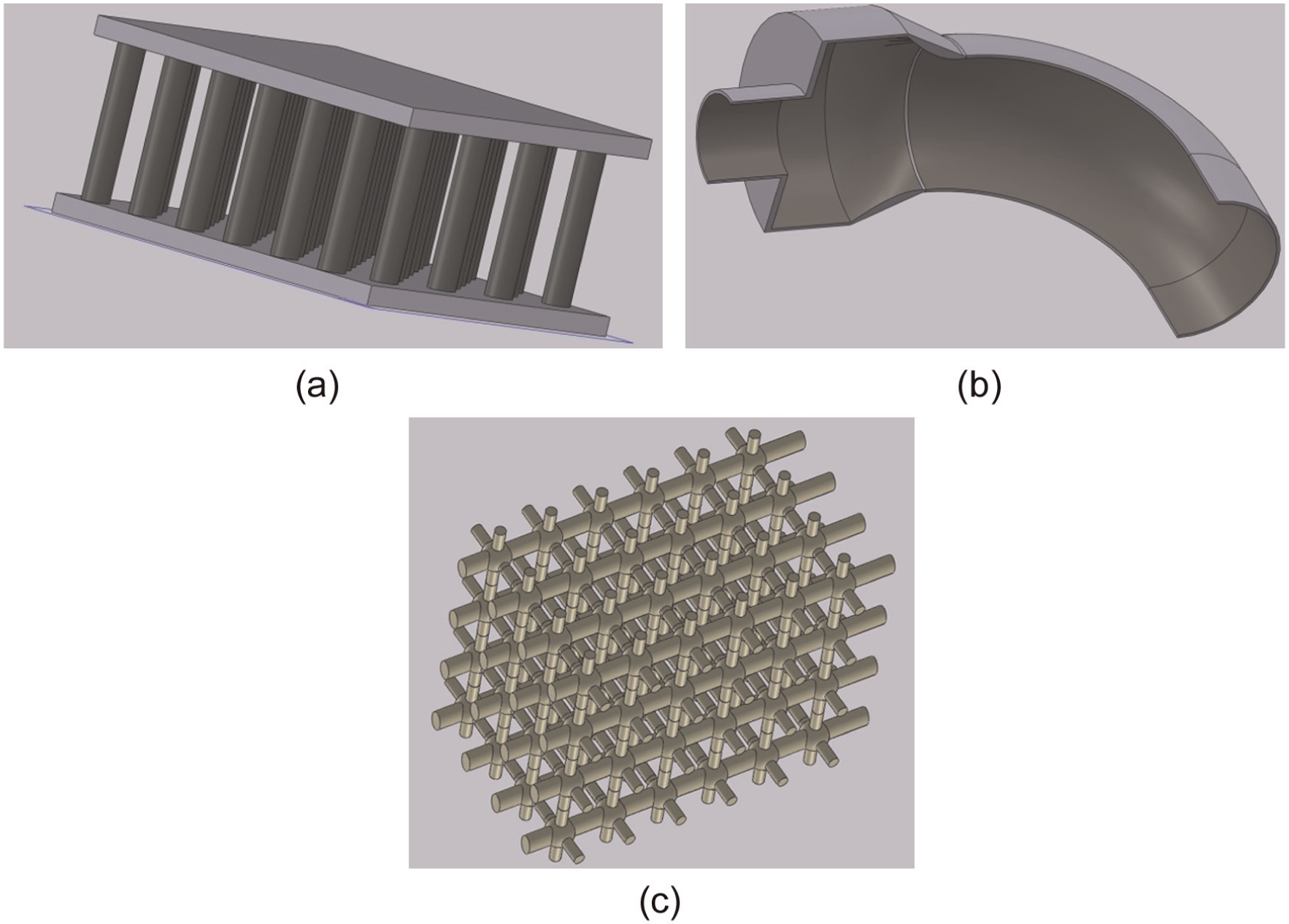
Illustrations of complex AM components: (a) cooling fins, (b) curved pipe with varying cross-sectional geometry and (c) scaffold structure.
Conclusion
The article presented here is an effort in consolidating the established finishing techniques for internal surfaces and highlighting future research directions. The major conclusions are as follows:
AFM is a mature finishing process for internal passages. Process parameters have been comprehensively explored and significant efforts have been made to improve the process capability by introducing hybrid AFMs. Internal surface reachability is a major advantage of this process. The ongoing attempts at exploring abrasive media variants might provide a breakthrough in producing even finer surface finish.
MAF for internal surfaces is a process with vast potential. Finishing force can be controlled locally by altering the external magnetic field distribution. This is not achievable on AFM and FBM as local flow manipulation is not possible. With very fine surface finish produced and its capability on very small channels, MAF could find applications in precision finishing of most internal passages.
In FBM, an unconventional fluidized bed hydrodynamic principle is used to manipulate abrasive actions. The important advancement of FBM is in finishing difficult-to-machine nickel-based alloy. Despite its promise in reachability of complex passages, experimental validations by other researchers are required for further advancement and commercialization of this technique.
There remains a wide area to be explored when it comes to the development of internal surface finishing techniques. AM technology has brought about a revolution in our expectations of internal passage complexity. Internal finishing solutions for AM components are thus urgently needed for the full potential of AM technology to be realized.
Footnotes
Declaration of conflicting interests
The author(s) declared no potential conflicts of interest with respect to the research, authorship and/or publication of this article.
Funding
The author(s) disclosed receipt of the following financial support for the research, authorship, and/or publication of this article: This work was conducted within the Rolls-Royce@NTU Corporate Lab with support from the National Research Foundation (NRF) Singapore under the Corp Lab@University Scheme.