
Abstract
In abrasive belt grinding process for surface of blade, elasticity, deformation and abrasive belt wear are major factors affecting the machining stability, efficiency and quality. In order to improve the grinding process and realize optimal grinding, a new controllable and flexible belt grinding mechanism is designed and assembled in a special computer numerical control grinding machine, accompanied with a constant grinding force control system. Based on the analysis of proportional valve and cylinder system in this grinding mechanism, a mathematic model of normal grinding force is constructed. Afterward, a fuzzy proportional–integral–derivative control strategy is proposed to deal with the uncertainty and nonlinearity of this system. A Simulink model of force control process is developed, and the good performance is achieved according to the simulation result. Finally, several grinding experiments for an aero-engine fan blade are carried out. The measurements show that the proposed grinding process with fuzzy proportional–integral–derivative force controller enhances the machining stability and efficiency considerably. What is more, the machining qualities, such as surface roughness, form accuracy and consistency, are improved significantly. And all the grinding results satisfy the machining requirements in the manufacturing process of blade.
Introduction
At present, more and more attentions have been paid to manufacturing of workpieces with complex and free-form surfaces in industry. Aero-engine fan and turbine blades are the typical representatives of these products. Due to their free-form surface, thin-walled structure and hard material of titanium alloy, their automatic grinding process is still difficult to be carried out well. In fact, surface deformation occurred frequently and tool marks still existed on the surface of blades after the current grinding process. The machining qualities of blades, for example, roughness, accuracy and consistency, which play a very important role in guaranteeing the correct function of the aero-engine are influenced by those factors. Therefore, as an important and final procedure, more studies on the grinding process for blades need to be focused on to prevent workpiece from damage and obtain best machining quality.
Especially, grinding force has a major influence on the overall grinding process of free-form surface. Not only the dynamic performance of equipment is profoundly influenced by grinding force, but also the surface qualities of blades are affected due to irregular changes of grinding force. Additionally, because of the surface waviness generated in the milling process, sudden changes in grinding force will lead to vibration and bring serious damage to blades.
Considering these challenges, grinding force and its control techniques have been studied widely by many authors. Grinding force models, such as the stochastic force model, 1 empirical force model, 2 chip formation force model, 3 sliding force model, 3 simple but accurate specific normal force model 4 and so on,5,6 have been proposed and validated. Patnaik Durgumahanti et al. 7 built both normal and tangential force prediction models based on the chip formation mechanism in the grinding process. Experimental evaluation of grinding forces was studied by Thiagarajan et al. 8 in cylindrical grinding based on grinding parameters. Several studies on force measurement and control system were carried out.9–11 A measurement system consisting of a sensor, an amplifier and a personal computer was set up by Li et al. 12 to obtain the accurate signals of the grinding force in the unsteady-state grinding process. And an automatic grinding system with a grinding force controller on a computer numerical control (CNC) machining center was developed by Liu et al. 13 to deduce the force variation and surface roughness.
Besides, grinding system simulation and process optimization have been studied widely.14–18 Vishnupad and Shin 19 presented a generalized intelligent grinding advisory system which can accommodate a huge number of grinding conditions. The trajectories analysis was used to optimize machining parameters by Hou et al. 20 first in the spherical grinding process. Li et al. 21 presented an optimum system for the cylindrical plunge grinding process to improve the grinding efficiency. In this research, an optimal model was built and the relevant simulation was carried out. It was proved that this optimal system had reduced grinding time largely. Additionally, another grinding process parameter optimization was carried out by Rao and Pawar 22 using artificial bee colony, harmony search and simulated annealing algorithms. The results showed that the performance of parameter optimization was equally good.
Apart from the researches described above, some researches have taken free-form surface grinding into account.23–25 Structural dimension optimization for grinding complex shaped surface was studied by Gao et al. 26 in robot belt grinding system. They proposed the new concepts of dexterity grinding point and space. Through the analysis and simulation, the optimization method was valuable to designing grinding system for improving the quality and productivity of complex shaped surface. Zhang et al. 27 demonstrated a local grinding model to simulate the belt grinding process for free-form surface. The new force model was also put forward considering the nonlinear relationship between the local contact situation and force distribution. Another research was developed by Rausch et al. 28 for grinding free-formed surface. The simulation of numerical control (NC) grinding process was presented. And the process forces were calculated based on the engagement situation of each grain on the tool.
According to the above descriptions, most of the force models were studied and built on the basis of process parameters, such as grinding depth, grinding width, grinding wheel velocity and feed rate. What their research focused on was the relationship between grinding force and process parameters. However, the accuracy of these force models could not be guaranteed because of the process complexity and nonlinearity caused by abrasive wear, grit adhesion and so on. What is more, it was difficult to adjust grinding force via parameter modification due to complex NC codes in the five-axis machining process. In addition, most of the recent studies on grinding force were applied in the cylindrical grinding process. Researches on the grinding process with the force controller for free-form surface were still insufficient.
Therefore, further techniques still need to be studied in research area of the grinding process for blades. And a suitable mechanism is also required to avoid the breakdown to blades caused by rigid contact between the blade and the grinding wheel. Considering the advantages of constant force grinding in reducing the negative impact created by abrasive wear, 29 a flexible belt grinding mechanism is developed with more effective force measurement and controller in this study. And the normal force in this grinding process can be adjusted easily through the movement of actuator in this new grinding unit. Furthermore, the feasibility of this grinding process with force controller for blade is validated through the grinding experiments.
Structure of flexible grinding system
As shown in Figure 1, fan and turbine blades are the main components of aero-engines. With the continued development of aerodynamics, materials and structure technology, blades of new generation are developed with much larger size and more complex shape. Accordingly, it becomes more and more difficult to machining blades and obtain high-quality surface under the present condition.
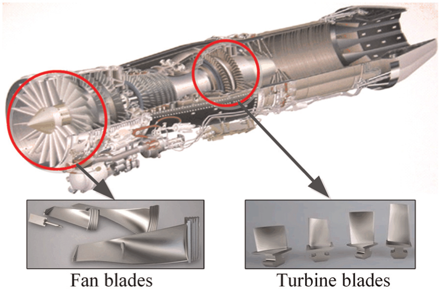
The geometric feature of fan and turbine blades in aircraft engine.
Flexible belt grinding mechanism
In order to achieve flexible contact between the blade and grinding tool, a new belt grinding mechanism is proposed. As shown in Figure 2, it consists of force sensor, control cylinder, grinding wheel, flexible actuator, tensioning cylinder, belt deviation rectifying mechanism, rollers, driving wheel and so on.
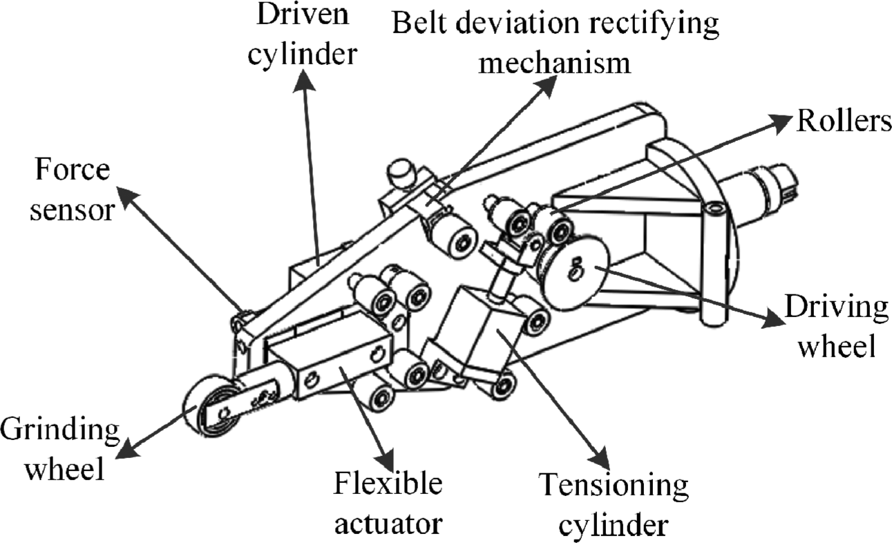
The structure of belt grinding mechanism.
The core of the above mechanism is that the changes in the normal grinding force can be compensated through the small linear displacement of the grinding wheel. The motion of the grinding wheel linked with a flexible actuator is driven by a cylinder which is controlled by a proportional valve. In this case, the small grinding depth can be revised through this grinding mechanism with the force controller rather than the CNC machining program. Simultaneously, the real-time detection and adjustment of normal grinding force are realized by the force sensor and control system. In other words, the advantage of this mechanism is that the grinding force as well as the grinding depth can be adjusted and kept constant during the grinding process. This will reduce the machining nonuniformity and workpiece damage which are caused by tool wear and grit adhesion over a period of grinding time.
Structure of grinding system
Based on the grinding mechanism mentioned above, the structure of this grinding system with the force controller by utilizing fuzzy theory is shown in Figure 3. The main idea of this system is to adjust the normal force and keep it constant automatically on the basis of the real-time force detector and the fuzzy controller. The signal conversion and transfer process are shown in Figure 4. First, the voltage signals generated in force sensor are sent to the data acquisition cards in the industrial computer. Through the calculation by the force control program, the adjusted voltage signals are sent to both proportional valve and cylinder. Finally, driving through the cylinder, the normal grinding force is kept constant during the grinding process. With the goal of handling the nonlinearity and uncertainty of grinding force system, the fuzzy proportional–integral–derivative (PID) control strategy is employed here. Compared with the traditional control theory, the amount of computation task and time are reduced obviously in the fuzzy-PID force control system.
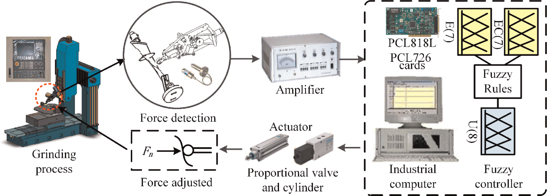
Belt grinding system with force controller.
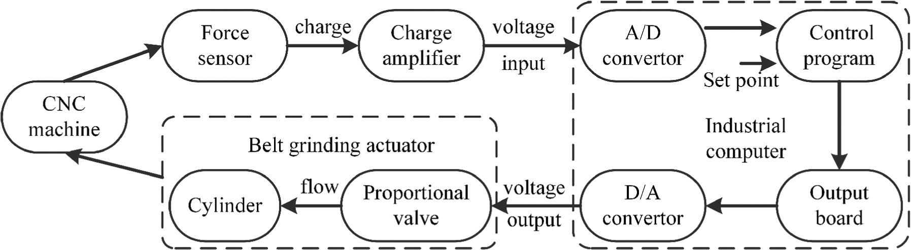
Signal conversion and transfer process in grinding system.
Mathematical model of normal grinding force
In the working process of this new grinding mechanism, the normal force detection and adjustment are achieved by the force sensor and the driving of cylinder, respectively. Combining the cylinder with the proportional valve, a pneumatic actuator system is constituted in this process. To better discuss the normal grinding force, a schematic diagram of the pneumatic proportional valve and cylinder system with gas as energy transfer medium is drawn as shown in Figure 5.
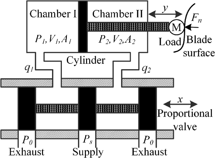
Schematic diagram of proportional valve and cylinder system.
Generally, the gas model consists of state equation, mass conservation equation, continuous flow equation and energy equation. However, several assumptions are made as follows in order to simplify the system and use the equations that follow: 30
The medium is the ideal gas in this system, and the ideal gas state equation can be used all the time.
The pressure and temperature of the gas source are constant. And it is an adiabatic system without any heat exchange.
The cylinder is completely enclosed without any gas leakage. The condition of the gas in the cylinder can be treated as a quasi-static process.
The kinetic and potential energy of the gas are negligible.
Energy balance equation
The first law of thermodynamics can be described by the following equation
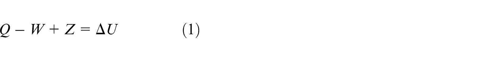
where Q is the heat transfer term, W is the change in the work done, Z is the energy brought by outside environment and ΔU is the change in the internal energy. Therefore, the energy equation in the proportional and cylinder system is shown as
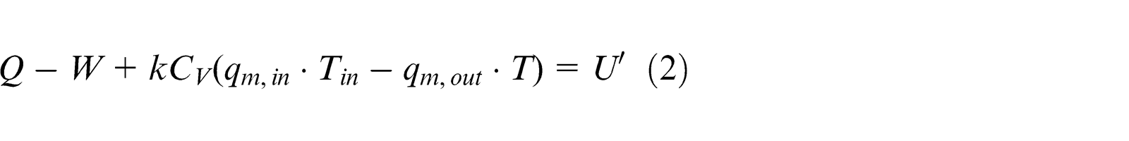
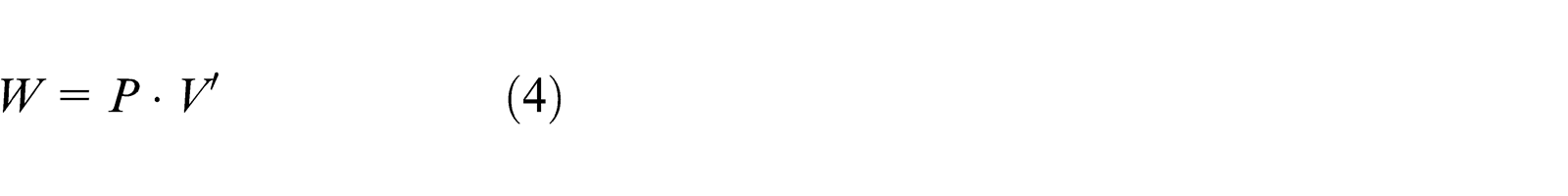
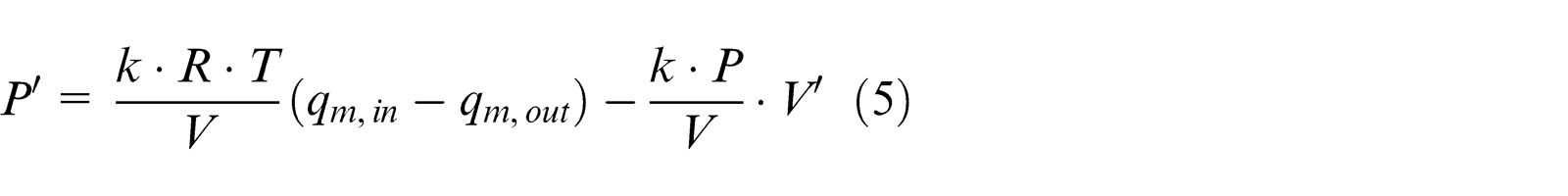
where k is the specific heat ratio, CV is the specific heat at constant volume and qm,in and qm,out are the input and output mass flow, respectively. Tin is the temperature of the input gas flow. With the symbols of volume V, mass m, pressure P and temperature T, the change in internal energy U′ and the change in the work done W can be expressed as the following equations
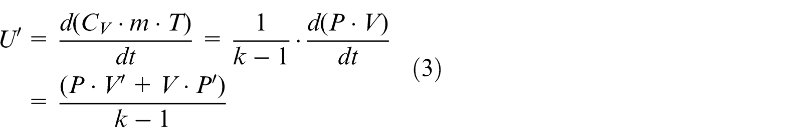
where
In this system, the piston is originally positioned at the middle of the chamber. When there is a very small displacement y, the volume equations in both chambers can be expressed as
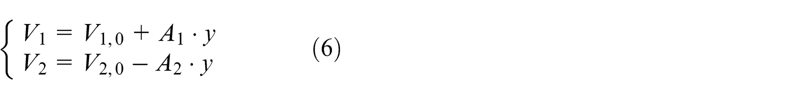
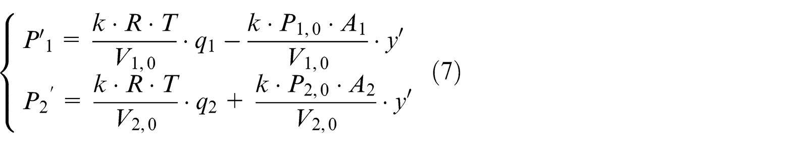
where V 1,0 and V 2,0 represent the initial volume of chambers I and II, respectively. Defining the initial pressure of chambers I and II as P 1,0 and P 2,0, respectively, the state equations in chambers I and II are simplified and linearized as follows
Mass flow equation
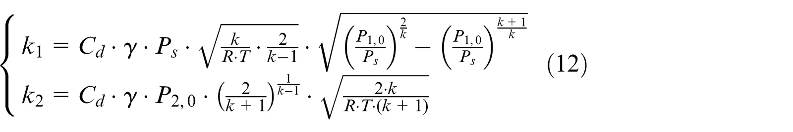
Generally, the mass flow through the tube is considered to describe the gas flow property in the proportional valve. And it can be viewed as one-dimensional isentropic flow. The mass flow of the supply and the exhaust in proportional valve can be expressed as the following equations, respectively, which were originally proposed by Sanville 31
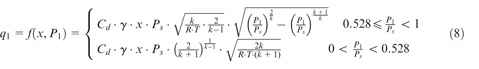
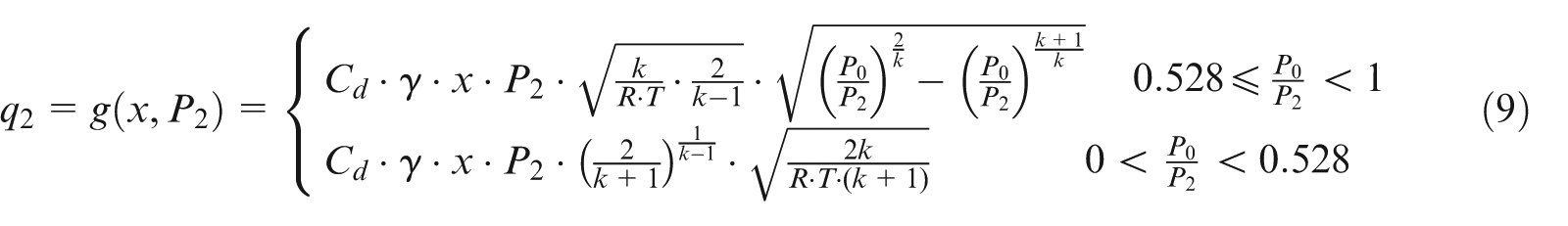
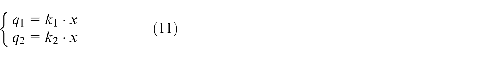
where Cd is the discharge coefficient, γ is the gradient of valve orifice area, x represents the displacement of the spool and Ps = 0.5 MPa and P 0 = 0.1 MPa are the pressure of gas resource and atmosphere, respectively. Considering qm as the function of x and P 1 or P 2, equations (8) and (9) can be linearized and simplified from Taylor series expansion. It yields
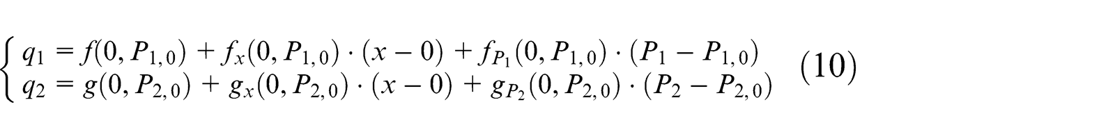
where
where
State equation of cylinder
Regarding the piston of cylinder as research object, its motion equation can be described as
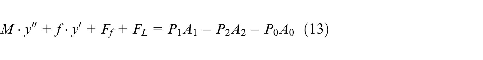
where M is the mass of load and piston, y is the piston displacement, f is the viscous damping coefficient and Ff and FL are static frictional force and load force, respectively. P 1 and P 2 are the absolute pressure of chambers I and II, respectively. P 0 is the atmospheric pressure. A 1 and A 2 represent the effective area of each chamber, respectively. A 0 represents the area of the piston rod, which satisfies the equation A 0 = A 1 − A 2.
To simplify the frictional force in the cylinder, the following linearizing equation is used here 32
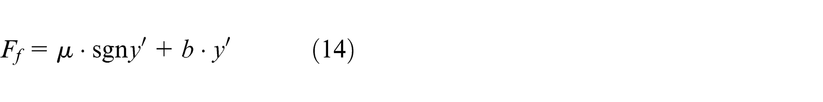
where µ is the Coulomb friction coefficient and b is the viscous friction coefficient.
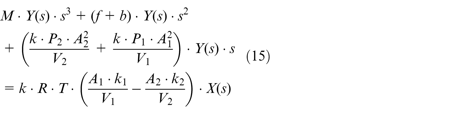
System transfer function
Combining equations (7)–(14) and their Laplace transformation, the transfer function of the system can be expressed as the following equation
It can be rearranged in the following transfer function form
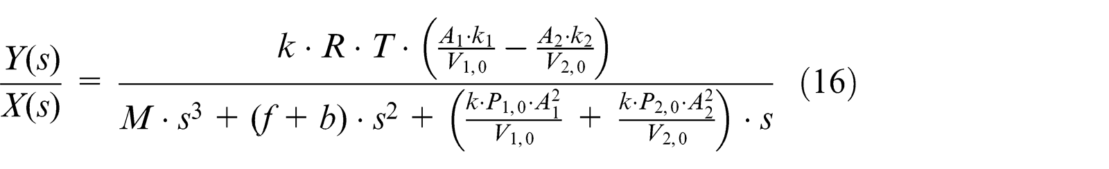
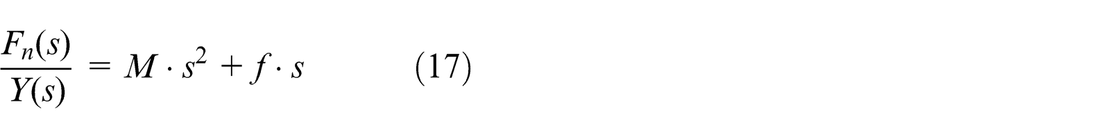
In the force control system of the cylinder, the Laplace transformation of normal force can be simplified and described as
According to the related literature, 33 the transfer function between input voltage U and displacement x can be characterized as a second-order oscillation link during the working process of the proportional valve. This function can be expressed as
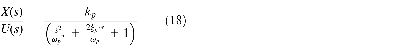
where kp, ωp and ξp represent gain, natural frequency and damping ratio of the proportional valve, respectively.
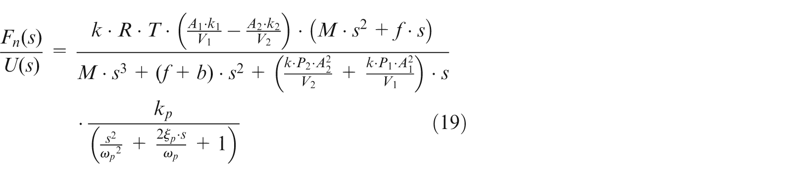
Force mathematical model
Through the above analysis and calculation, the mathematical model of normal grinding force can be obtained by equations (16)–(18)
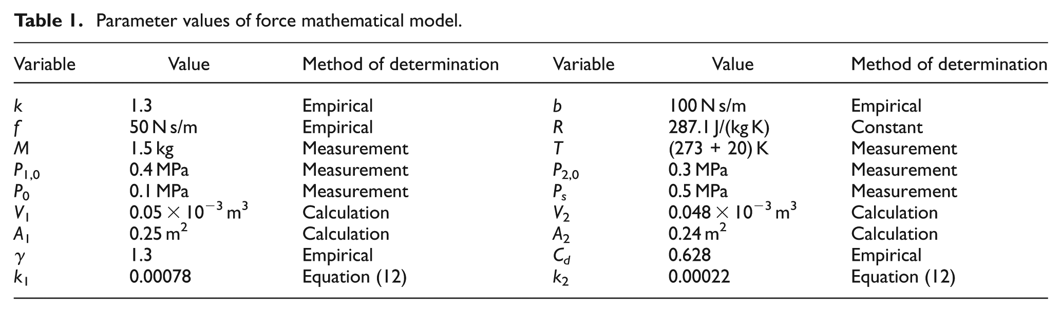
The parameter values of the force mathematical model are shown in Table 1. Generally, specific heat ratio k is determined by the composition of the gas. For monatomic gas, the specific heat ratio k ranges from 1.66 to 1.67. For diatomic gas, it ranges from 1.40 to 1.41. For polyatomic gas, it ranges from 1.10 to 1.3. Here, the medium gas is treated as the polyatomic gas which is primarily made up of diatomic gases (nitrogen (N2) and oxygen (O2)). So, the value of 1.3 is used in this mathematical model. The values of viscous damping coefficient f, viscous friction coefficient b, discharge coefficient Cd and gradient of valve orifice area γ are all obtained by means of the empirical value. 34 The methods of determination for other values in the mathematical model are also explained in Table 1.
Parameter values of force mathematical model.
The function of proportional valve can be negligible for its fast response in this system. And considering the amplifier and sensor as proportional components, the open-loop transfer function is simplified as G(s) = K·Fn(s)/X(s). However, the delayed effect caused by mechanical defect has been ignored in the above analysis of the system model. Through calculation and simplification, the transfer function is expressed as equation (20). Then, the system block diagram is obtained as shown in Figure 6. It is easy to prove that this is a stable system by Routh–Hurwitz stability criterion
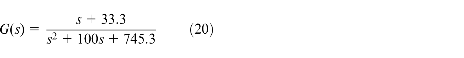
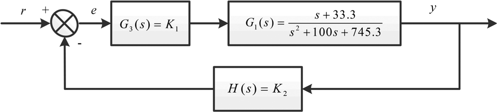
Block diagram of closed-loop transfer function.
Force control strategy
However, in the above analysis, the mathematical model of normal grinding force is not really accurate enough. Many factors, such as temperature change, heat exchange, cylinder leakage and external environment influence, have been ignored during the modeling process. If these factors were considered, system complexity, nonlinearity, instability and uncertainty would bring great difficulties in the force control system. Thus, single and simple PID controller will be difficult to achieve precise control of grinding force. In view of the advantages in dealing with nonlinear, time-varying and delay systems, fuzzy-PID control strategy is employed in this article.
As shown in Figure 7, the proposed fuzzy-PID controller has two inputs, namely, the force error E and the derivative of force error ΔE. The changes in PID parameters ΔKp, ΔKi and ΔKd are regarded as outputs. The membership functions (MFs) for the input and output variables are shown in Figure 8, where the universe of discourse for each input is normalized over the interval [−6, 6]. The fuzzy variables are labeled as “NB”, “NM”, “NS”, “ZE”, “PS”, “PM” and “negative big”, “negative medium”, “negative small”, “zero”, “positive small”, “positive medium”, and “positive big” respectively. Symmetrical triangular uniformly distributed MFs are assigned for the input and output variables. Meanwhile, the rule base for computing the output variable is given according to the expert rules.
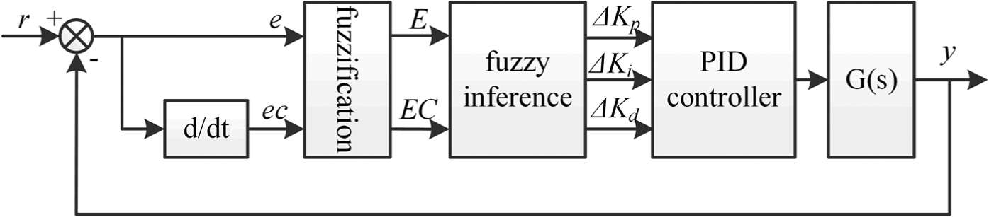
Block diagram of fuzzy-PID control system.
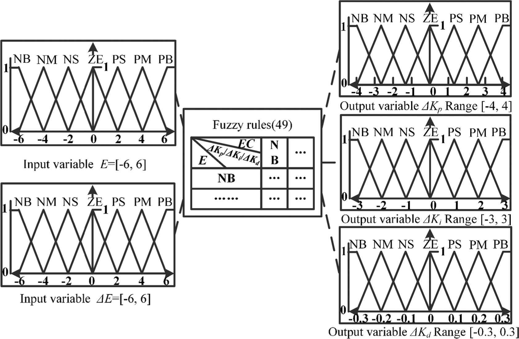
Membership functions of variables in fuzzy controller.
To determine the performance of the control system, the Simulink model of this control process is established. As shown in Figure 9, a simple closed-loop simulation program is constituted using the fuzzy-PID controller. From the response of the control system shown in Figure 10, control strategy with the fuzzy controller runs well with quick dynamic response, small overshoots and high accuracy of the steady state.
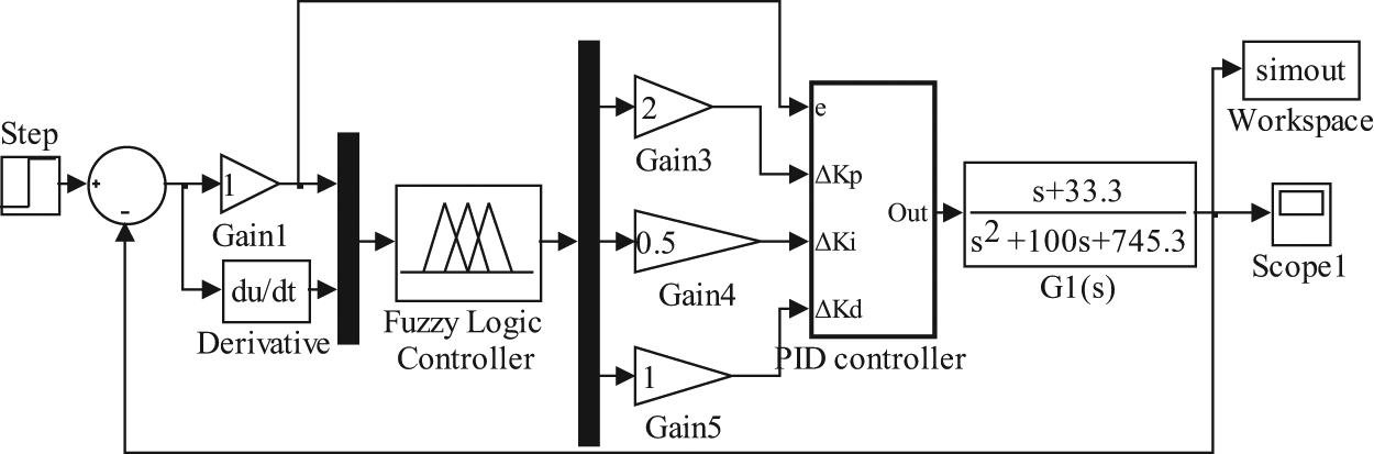
Simulink model of fuzzy-PID force control system.
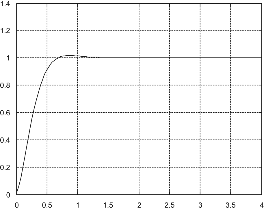
Step response of fuzzy-PID force control system.
Experiments and testing results
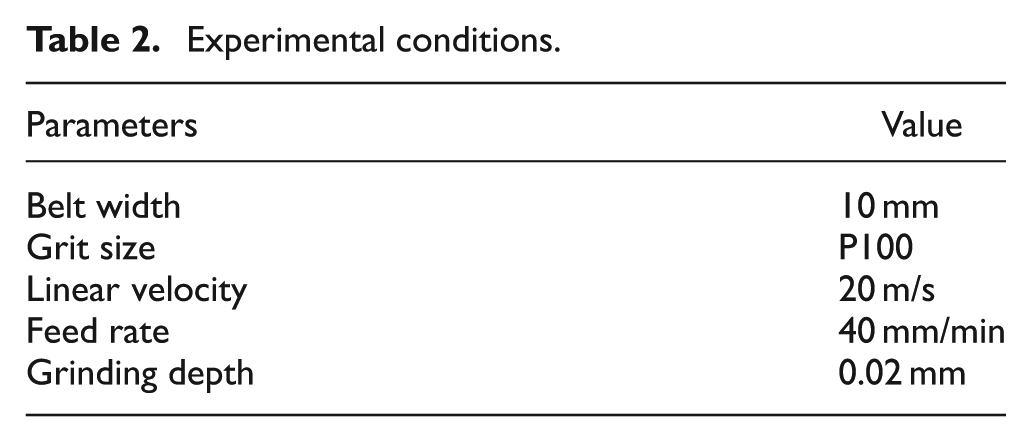
Grinding experiments in this study are carried out on the special five-axis belt grinding CNC machine with flexible grinding mechanism. It is a double-column machine with two rotary tables as shown in Figure 11(a). The numerical control system used in this machine is Siemens 840D. The force control system is developed on an industrial computer (Advantech IPC-610-H) with PCL818L data acquisition cards and PCL 726 cards. In the following experiments, the workpiece is a titanium alloy fan blade with linear size of 800 mm and turning diameter of 300 mm as shown in Figure 11(b). After the same milling process, the conditions of both convex and concave surfaces are considered identical before the grinding process. And these two rather rough surfaces are used as the grinding objects in the experiments. The machining tool used for grinding titanium alloy blade is an abrasive belt with material of silicon carbide. Other experimental conditions are listed in Table 2 according to industrial guide and machining experience.
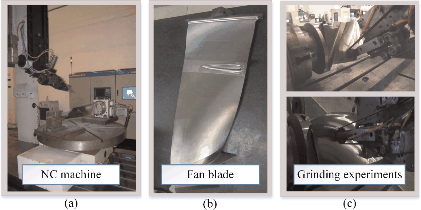
(a) Grinding apparatus, (b) workpiece and (c) experiments.
Experimental conditions.
In order to verify the effectiveness of the grinding process with force controller, two sets of experiments are carried out. The main difference between them lies in whether the force controller is used in the grinding process. The experiments with and without the force controller are conducted on convex and concave surface, respectively, as shown in Figure 11(c). The grinding path is planned in Unigraphics (UGS18), and the NC code is generated through the calculation of post-processing algorithm.
The comparison of surface appearances after grinding with and without fuzzy-PID force control system is shown in Figure 12. The roughness and form accuracy of surface after grinding are measured by roughness measuring instrument (Mahr MarSurf M300C) and three-coordinate measuring machine (GLOBAL STATUS 121510), respectively (see Figure 13). Several test points on both convex and concave surfaces are chosen to be measured after the experiments. Figure 14(a) and (b) displays the roughness test results (R profile) in the grinding process with and without force controller, respectively. For comparison, the surface roughness test result before the grinding process is also obtained as shown in Figure 14(c). Other results such as surface form accuracy and marks are listed together in Table 3. Finally, to observe the changes in the normal grinding force, sampling data are obtained and shown in Figure 14.
Measurement results of machining quality.

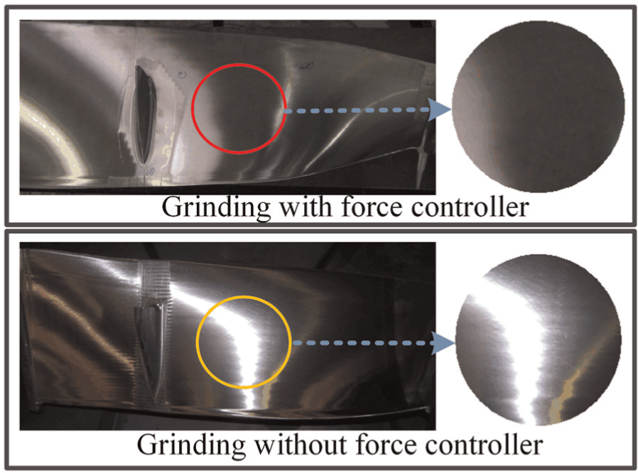
Blade surface appearance after rough grinding.
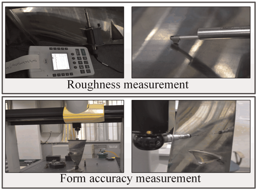
Roughness and form accuracy measuring process.
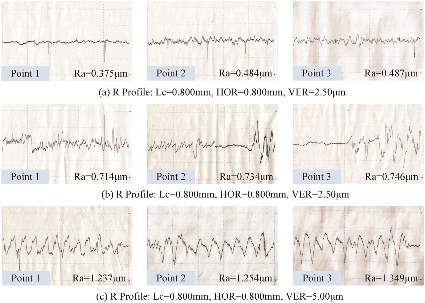
Roughness test results of different processes: (a) grinding with force controller, (b) grinding without force controller and (c) before the grinding process.
From the grinding test results mentioned above (see Figures 12 and 14, and Table 3), it can be seen that a significant improvement in machining quality is achieved after grinding with the force controller. The surface roughness in the process with the force controller is improved by up to nearly 30% when compared with the grinding process without it. The form accuracy of surface is reduced effectively from ±0.12 to ±0.08 mm (33% improvement). This has satisfied the machining requirements of blade in its manufacturing process. Moreover, tool marks are invisible by visual inspection, and better surface consistency is obtained after the grinding process with the force controller. On the contrary, tool mark is visible and consistency is poor after grinding without the force controller. Such a situation is mainly caused by the inconsistency of grinding depth in different grinding steps. Besides, the slight waviness in Figure 12 is mainly caused by the tool path designing. And sometimes, the tool path is influenced by the elastic deformation of the abrasive belt. In addition, it can be seen from Figure 15 that the normal force is maintained constantly in process with the force controller. Otherwise, in the grinding process without the force controller, the normal force has a remarkable decline (by approximately 20%) within a period of time due to the wear of the abrasive belt. The force declining will reduce the material removal ability in the grinding process. In other words, the higher material removal ability is maintained during the grinding process with the force control system. As a final note, the small-scale grinding force changes exist in both grinding processes with and without the force controller. This situation is fundamentally caused by the machining material inhomogeneity and elastic deformation during the grinding process. As it is well-known, the belt wear and short-term adhesion are unavoidable during the process. Therefore, the short-term adhesion of wear debris in the grinding process will slightly aggravate the influence of material inhomogeneity on grinding force changes.
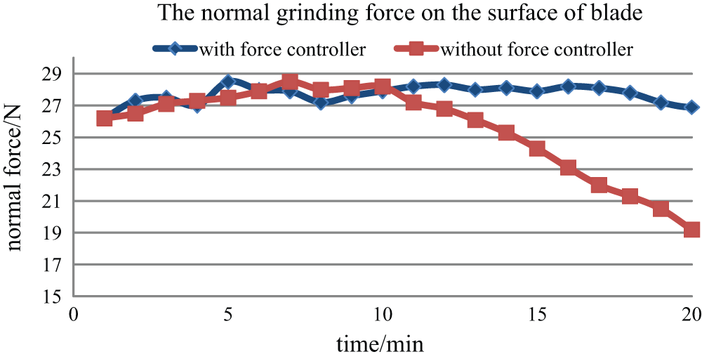
Comparison of normal force changes in belt grinding with and without force controller.
Conclusion
Regarding the high-quality requirements on manufacturing of aero-engine fan and turbine blades, a new belt grinding mechanism is proposed to realize constant force grinding in this study. Based on the mathematical model of proportional valve and cylinder system, a fuzzy-PID controller is designed to solve the nonlinearity and uncertainty of this system. It is proved that the force control system performs well with quick dynamic response through the simulation result. After the grinding experiments to a fan blade, the machining quality in the grinding process with the force control system can be improved and guaranteed more efficiently according to the measuring results. Besides, not only the surface roughness and form accuracy are improved significantly, but also the material removal ability is well maintained during a period of time.
Footnotes
Appendix 1
Acknowledgements
The authors would like to thank the editors and the anonymous referees for their insightful comments.
Declaration of conflicting interests
The authors declare that there is no conflict of interest.
Funding
This study was supported by National Natural Science Foundation of China (51005184) and Aeronautical Science Foundation of China (2012ZE53061), as well as the financial support to the first author under the China Scholarship Council (CSC)-Concordia University program as a visiting researcher under the supervision of the second author.