
Abstract
The accuracy requirement of ultra-precision involute artefacts and master gears, which are used to calibrate the gear measuring machines, is increasing as power density increases; however, the complexities and specificities in the involute processing and measuring have been the bottleneck of manufacturing technique for high-grade involute artefacts and ultra-precision master gears. In order to develop the ultra-precision involute gear profile, related researches were conducted in this study. First, the manufacturing level of high-grade involute artefacts was introduced. Then, the forming principle of the involute was discussed, and the roller–rail type and cam–baffle type of mechanical generating mechanism with little effects of driving accuracy on generating accuracy and less error sources were pointed out. Finally, the double roller–rail type of grinding and measuring devices for high-grade involute artefacts were designed according to the optimal forming principle of the involute, and a precision grinding experiment on an involute cam (a kind of high-grade involute artefacts) was conducted. The measured results show that the total profile deviation is not more than 0.6 µm and the profile form deviation is less than 0.4 µm in 105 mm generating length of the specimen. By using the refined involute cam and gear grinder with cam–baffle type of mechanical generating mechanism, a precision grinding experiment on the specimen of a master gear was conducted. The experimental results verify that the roller–rail type of mechanical generating mechanism has the processing capacity of high-grade involute artefacts with submicron-level profile accuracy and the refined gear grinder with cam–baffle type of mechanical generating mechanism has the processing capacity of ultra-precision master gear with grade-1 profile accuracy.
Introduction
The involute surface is widely used as the profile of gears and splines due to its advantages in transmission. However, the complexities and specificities of the involute surface make the processing and measurement difficulties for it. The high-grade involute artefacts (HIA) and the high-grade involute cams (a kind of HIA with a larger generating angle), which are used as the measuring and processing datum of the involute, have higher accuracy requirement for involute profile near noise levels. Internationally, the accuracy indexes of the involute artefact often reference the definitions of gear profile form deviation ffα, gear profile slope deviation fHα and gear total profile deviation Fα according to gear international standard ISO 1328-1:1995.1,2 Considering the high processing difficulties of HIA, the double ball artefact (DBA), which allows the compensation, can be used to calibrate the measurement uncertainty of gear measuring instruments (GMI) or coordinate measuring machines (CMM) in some measurement institutes.3 –7
According to the report, German National Physical Laboratory (Physikalish-Technische Bundesansalt (PTB)) can develop HIA with profile form deviation ffα=0.5 µm, which is used to transfer the involute quantity value both in Germany and in other countries in Europe, 8 but no detailed processing techniques and methods about HIA are introduced. Changchun Institute of Optics, Fine Mechanics and Physics (CIOMP), Chinese Academy of Sciences, can develop HIA with profile form deviation ffα=0.8 µm and its accuracy is superior to grade 1 according to ISO 1328-1:1995 by using the roller–rail generating mechanism. 8
In order to develop HIA with submicron-level form profile accuracy and ultra-precision master gears (UMG) with grade-1 profile deviation, the remainder of the article is organized as follows: the next section discusses the optimal forming principles of the involute. ‘Grinding and measuring device of HIA’ section designs the double roller–rail grinding and measuring devices for HIA according to the optimal forming principle of the involute. A precision grinding experiment on an involute cam (a kind of HIA with a larger generating angle) is conducted in ‘Grinding experiment on an involute cam’ section and ‘Grinding experiment on a master gear’ section performs a precision grinding experiment on an involute master gear to demonstrate the feasibility and validity of the double roller–rail and the cam–baffle generating method, respectively. Finally, conclusions are drawn with a brief summary in ‘Conclusion’ section.
Optimal forming principle of an involute
Known by the generating principle of the involute, when a line does pure rolling movement around a circle, the trajectory of the arbitrary point on the line is an involute whose base circle is the above circle. Based on the principle, the following involute processing methods are derived.
Electronic generating method
Most of the generation systems of the computer numerically controlled (CNC) gear cutter grinders and the wheel dressing system of CNC forming wheel grinders widely use the electronic generating method to generate an involute. The generating movements are realized by a rotary stepping motor and a linear stepping motor to drive two proportional rotation and translation, respectively. The generating accuracy of the workpiece is mainly from the driving accuracy of the rotary stepping motor and the linear stepping motor, the synchronous accuracy of the two movements and the stability of electronic signals. Considering the more error sources and the disadvantages (drift, hysteresis and vulnerable to interfere) of the electronic signals, the processing accuracy of the involute is relatively low by using electronic generating method. Generally, the gear involute processing accuracy can reach to grade 4-2. According to the current processing and CNC technology, the electronic generating method cannot meet the processing requirement of HIA and UMG.
Mechanical generating method
The generating movement of the involute can be realized by specific mechanisms. The prominent advantages of those kinds of mechanisms are that the generating movement can be performed by one motor and the driving accuracy of the motor has little effects on generating accuracy. Therefore, the involute profile processed by adopting specific mechanisms can obtain higher profile accuracy. According to the different kinds of mechanisms, the mechanical generating methods can mainly be classified into three types: roller–steel strip type, roller–rail type and cam–baffle type.
The roller–steel strip generating mechanism
The generation system of gear grinder with double dish wheels made in Switzerland MAGG company adopts the roller–steel strip generating mechanism. The sketch map of this generating mechanism is shown in Figure 1.
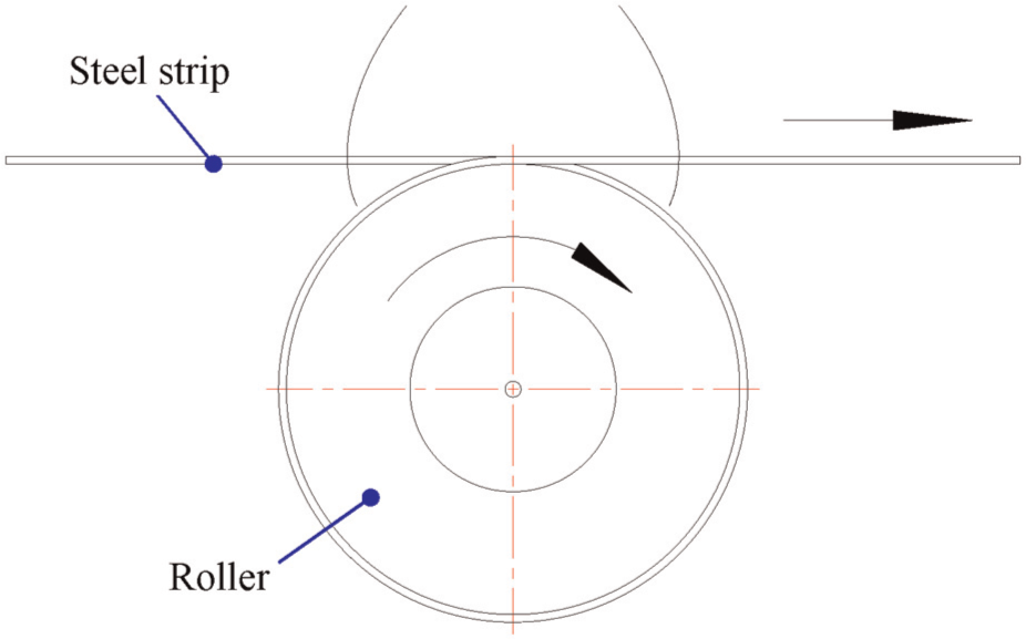
Sketch map of roller–steel strip generating mechanism.
The steel strip can be bended but cannot be stretched. When the steel strip twined around the roller does transition, the pure rolling of the roller is realized under the function of friction between the steel strip and the roller. The roller–steel strip generating mechanism matches with the generating principle of an involute and produces the involute directly (so called once-forming), so it has higher generating accuracy. The error sources of the roller–steel strip generating mechanism are mainly from the roundness of the roller, the processing accuracy of the steel strip (the thickness uniformity of the steel strip) and the rigidity of the generating system. Since the steel trip is a flexible body, the rigidity of the roller–steel strip generating system is much lower. Additionally, the thickness accuracy of the steel strip is hard to guarantee, which results in the difficulties to improve the generating accuracy of the roller–steel strip generating mechanism. Therefore, the flexible generating mechanism cannot meet the processing requirement of HIA and UMG.
The roller–rail generating mechanism
The roller–rail generating mechanism is widely used in the measuring system of HIA and UMG. German National Physical Laboratory (PTB), National Metrology Institute of Japan (NMIJ) and high-precision gear research room (HGR) of Dalian University of Technology (DLUT, China) adopt this generating mechanism to form an ideal involute to test the accuracy of involute artefacts and master gears.9 –12 Compared to the single roller–rail generating mechanism, the double roller–rail generating mechanism has the advantages of higher rigidity, averaging effect of errors of double rollers and double rails and little processing principle error. The double roller–rail generating mechanism with simple structure, less error sources and the involute is grinded by once-forming method, so this generating mechanism matches with the optimal forming principle of the involute and can meet the processing and measuring requirements of HIA and UMG.
The cam–baffle generating mechanism
The generating mechanism of gear grinders with the flat-faced wheel (such as Y7125 and Y7431 made in China) belongs to the cam–baffle type, and its working principle is shown in Figure 2. The involute cam and the workpiece are mounted on the machining spindle. When the spindle rotates, it will translate along the rail simultaneously under the function of the cam mechanism. The generating accuracy of such generating mechanism is mainly from the profile accuracy and the installation accuracy of the exploratory (i.e. the involute cam). 13 The cam–baffle generating mechanism is of simple structure, high rigidity and less error sources. Though the involute processed by cam–baffle generating mechanism belongs to twice-forming (the fabrication of the involute cam belongs to once-forming and the fabrication of gears using the involute cam belongs to twice-forming), the involute cam can obtain higher profile accuracy by once-forming devices (such as roller–rail grinding device). Compared to the roller–steel strip generating mechanism, there is no flexible body in cam–baffle generating mechanism, so the latter has higher rigidity and higher processing accuracy of an involute. Due to the easy-to-realize indexing, most of the processing of master gears, gear-shaping cutters and gear-shaving cutters are performed by cam–baffle generating mechanism. The refined master grinder Y7125 with the cam–baffle generating mechanism is conformed to have the capacities of processing UMG with grade-1 profile accuracy.14 –17
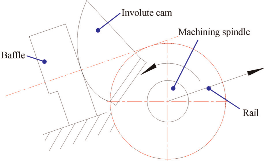
Sketch map of the cam–baffle generating mechanism.
Forming method
There is no generating movement in the processing system of the gear grinder with forming wheel. The processing accuracy of gear involute depends on the dressing accuracy of the involute profile and qualities (abrasives, grain size, hardness, bonded agent, etc.) of the grinding wheel. The dressing of the involute forming wheel is generally used by the electronic generating method or diamond wheel, so the dressing accuracy of the forming wheel is not high. And the gear involute belongs to twice-forming method (first forming the involute of the grinding wheel and then the workpiece). Therefore, the processing accuracy of forming wheel is much lower. Recently, with the breakthrough of the dressing technology of a grinding wheel, the grinding accuracy of forming wheel has been improved. According to the reports, the maximum gear-grinding accuracy can reach to grade 218 –19 by the forming method. Comparison results of the generating methods of the involute are shown in Table 1.
The generating methods of the involute.
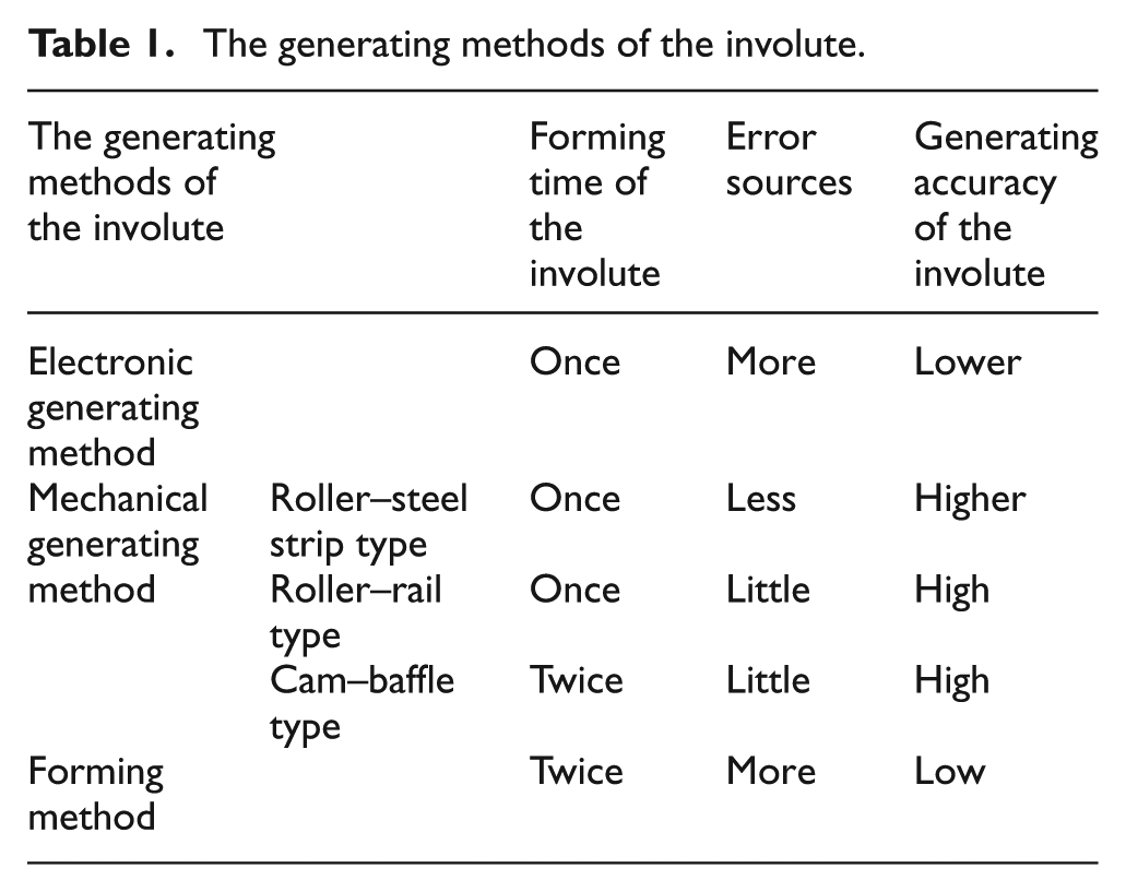
To sum up, the roller–rail type and cam–baffle generating mechanism match with the optimal forming principle of the involute. The former is used to produce HIA, and the latter is used to produce UMG. Since the involute is grinded by once-forming method, the roller–rail generating mechanism has higher processing accuracy of an involute. The article will adopt the roller–rail generating mechanism to study the ultra-precision grinding technique of an involute cam and then adopt the cam–baffle generating mechanism to study the ultra-precision grinding technique of UMG by using the refined involute cam.
Grinding and measuring device of HIA
The double roller–rail involute grinding and measuring devices are designed according to the optimal forming principle of an involute. The working principle of roller–rail generating mechanism is shown in Figure 3.
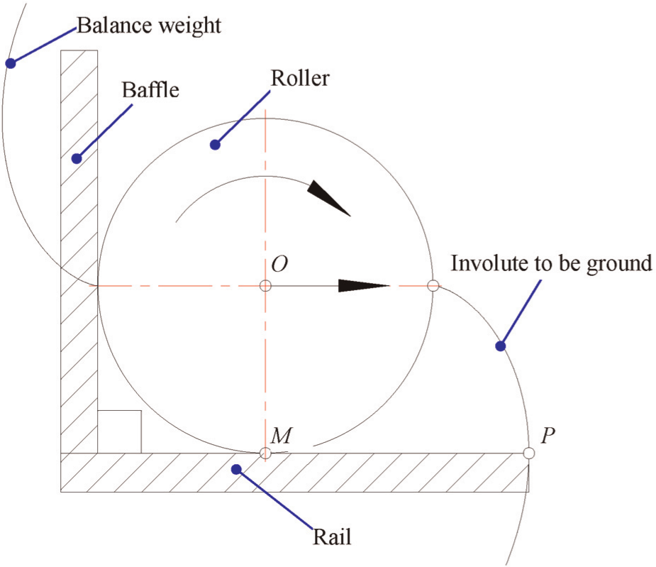
Sketch map of the roller–rail generating mechanism.
The function of the frame whose working plane is perpendicular to the rail plane is to ensure the consistency of the two rollers at the initial position. When the rollers do pure rolling movement on the rails, the trajectory of an arbitrary point on the rail plane is an involute whose base circle is the roller. Known by the generating principle of an involute, the involute to be ground is always perpendicular to the rail plane and their cross point P remains unchanged. According to the conclusion, measurement on the involute profile deviations can be realized by setting a replacement stylus on the position P and grinding on the involute can be carried out by setting a grinding wheel on the position P. However, the related researches on the processing field of the HIA using this method have not been reported. The prominent advantages of the roller–rail generating mechanism are that the driving accuracy and the feed accuracy of the generating mechanism have little effect on the generating accuracy of the involute. The pure rolling movement can be carried out by applying replacement driving at the geometric centre O of the two rollers.
The sliding phenomenon between the rollers and the rails is evitable by controlling the driving velocity under a critical value. The experiments show that the sliding phenomenon would not occur under a lower driving velocity. However, the elastic creep phenomenon is inevitable. Literature 21 analysed the issue of the elastic creep between the roller and the rail and drew the conclusion that the quantity of the elastic creep is at nanometre level. So the effects of elastic creep between the rollers and the rails on processing and measurement of HIA can be ignored.
There is a certain width of an involute artefact, so the touch line between grinding wheel and the involute artefact should be a line tangential to the involute and parallel to the rail plane. There are two ways to locate the grinding wheel: one way is using cylindrical face of the disc wheel as shown in Figure 4 and the other way is using end face of the cup wheel as shown in Figure 5.
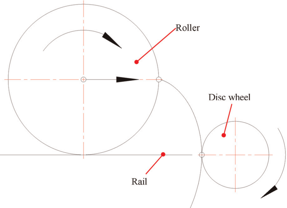
Grinding involute with disc wheel.
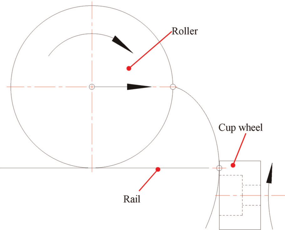
Grinding involute with cup wheel.
The grinding force of the disc wheel is parallel to the direction of movement of involute artefact at the grinding point, which will increase the motion instability of the rolling assembly. Furthermore, the radial vibration of the disc grinding wheel not only directly affects the processing accuracy of the involute profile deviations but also makes the touching line between the grinding wheel and the involute artefact vary on the rail plane, which further affects the processing accuracy of the involute profile. As for the cup wheel, as long as the end face of the wheel is guaranteed to be perpendicular to the rail plane, the cross line between the end face of the wheel and the involute artefact can be guaranteed on the rail plane. In view of the reason mentioned above, the ultra-precision processing of HIA should use the end face of the cup wheel. The new designed double roller–rail grinding device for the involute artefact is shown in Figure 6 and the measuring device is shown in Figure 7.
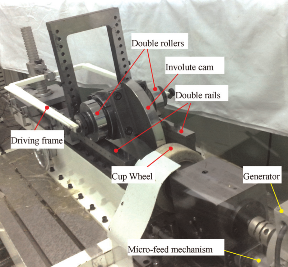
The double roller–rail grinding device.
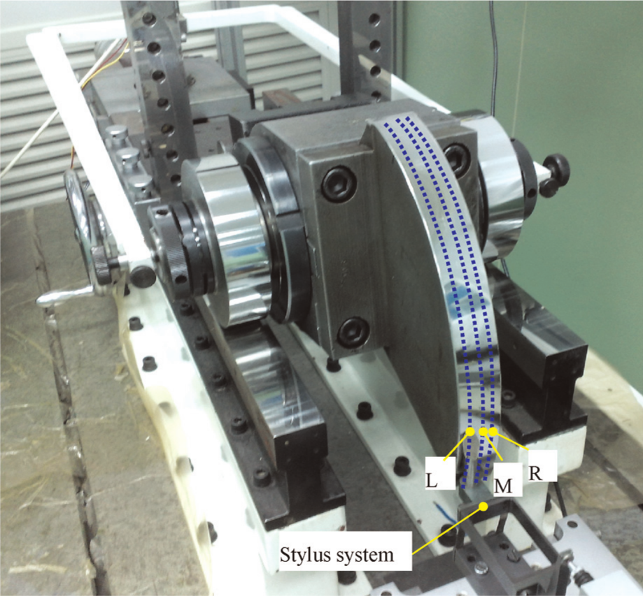
The double roller–rail measuring device.
Grinding experiment on an involute cam
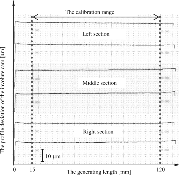
According to the processing mission of the grade-1 UMG, the precision grinding experiment is performed by the double rollers whose base circle djcam = 113 mm and the lengthened involute cam with designed generating angle to π/2 is used in gear grinder Y7125. Before grinding experiment, the roughness of the rollers and the flatness of the rails are obtained, which are not more than 0.5 µm, and the errors of the effective part corresponding to the calibration range of the involute cam are smaller. The differential-thread micro-feed mechanism that can obtain minimum feed with 0.2 µm is designed. The feed is controlled less than 1 µm during semi-finishing grinding with a driving velocity of 5 mm/s, while the feed is controlled less than 0.5 µm during fine grinding with a driving velocity of 2–3 mm/s. After finishing, the rolling assembly containing the involute cam is shifted to the double roller–rail measuring device for the involute artefact. After 24-h temperature balance at 20 ± 0.5 °C, the precision measuring on the involute cam is conduced. Due to the long generating length of the new designed involute cam, the calibration range is chosen from 15 to 120 mm. The results of profile deviations of the involute cam in three equidistant sections (left, middle and right sections as shown in Figure 7) are shown in Table 2.
Results of profile deviations of the involute cam
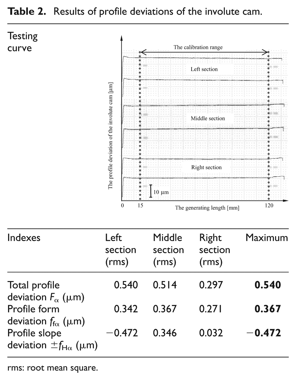
rms: root mean square.
The uncertainty U95 of the double roller–rail type of the measuring device can be obtained as 0.45 µm by error analysis. The measuring results show that the profile total deviation of the refined involute cam is not more than 0.6 µm and profile form deviation is less than 0.4 µm in the generating length of 105 mm, which is much higher than the commercial accuracy (about 2–4 µm). The processing accuracy of the involute cam is superior to grade 1 according to ISO 1328-1:1995 and reaches the international advanced level of HIA. The results show that the double roller–rail grinding device for the involute artefact matches with the optimal forming principle and has submicron-level processing accuracy of HIA.
Grinding experiment on a master gear
As for grinding master gears, the indexing system is necessary to realize the processing of every tooth involute. Since the double roller–rail grinding device for the involute artefact has no indexing system, the cam–baffle gear grinder is adopted for grinding UMG, in which the involute cam can be refined by the double roller–rail generating mechanism mentioned above.
The refined involute cam meets the processing requirement of UMG with grade 1-0 (ISO 1325-1:1995) profile deviation theoretically. The master gear with module m = 6 mm, tooth number z = 20 and press angle α = 20° is taken as the specimen, and a precision grinding experiment is performed by using appropriate wheel and grinder parameters and ultra-precision grinding processing method. 16 The cam–baffle mechanism in grinder Y7125 is shown in Figure 8.
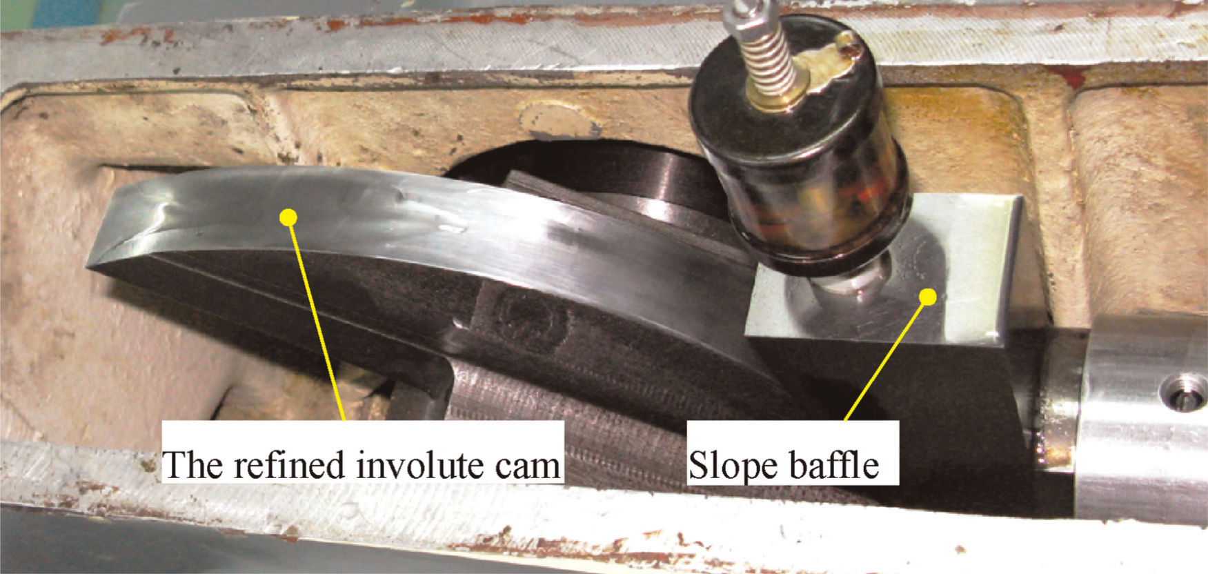
The cam–baffle mechanism in grinder Y7125.
After semi-finishing grinding, fine grinding, finishing and 24-h temperature balance at 20 ± 0.5 °C, the profile deviations of the specimen can be measured by the ultra-precision involute tester designed by high-precision gear research room (HGR) of DLUT, which is conformed to have the capacity of measuring grade-1 gear profile deviations.12,22,23 The ultra-precision involute tester (as shown in Figure 9) also adopts the double roller–rail generating mechanism which is the same as the measuring device of HIA.
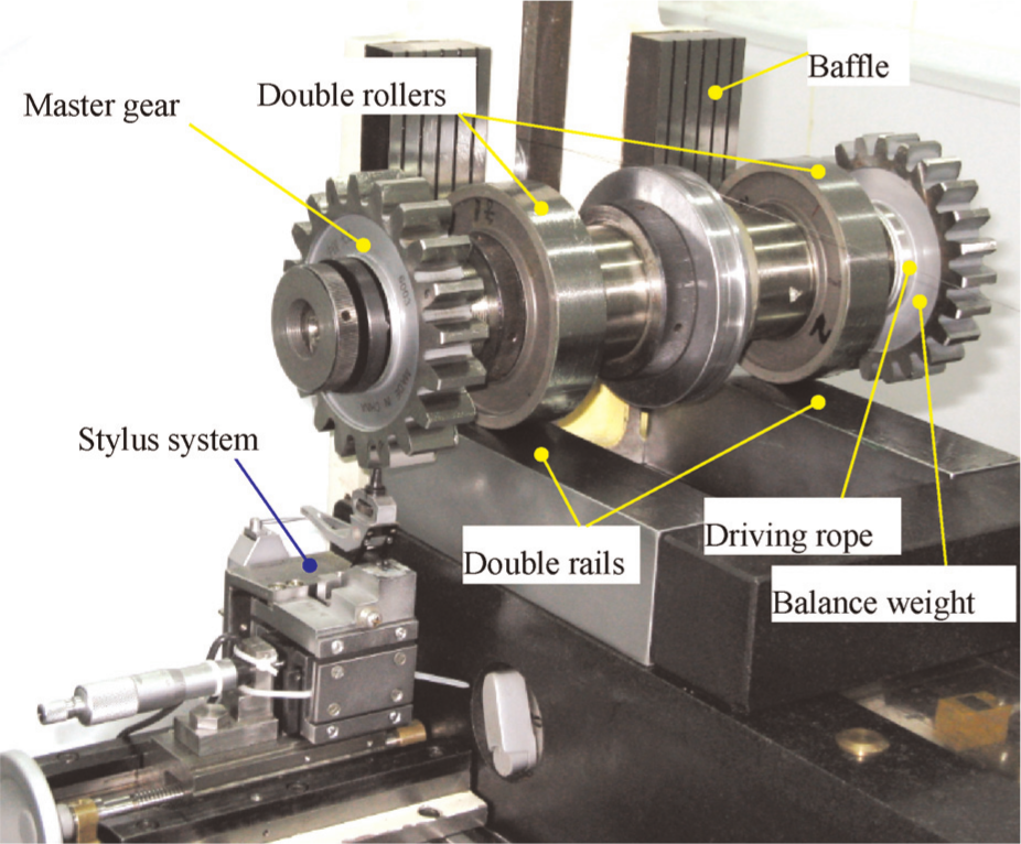
The ultra-precision involute tester for UMG.
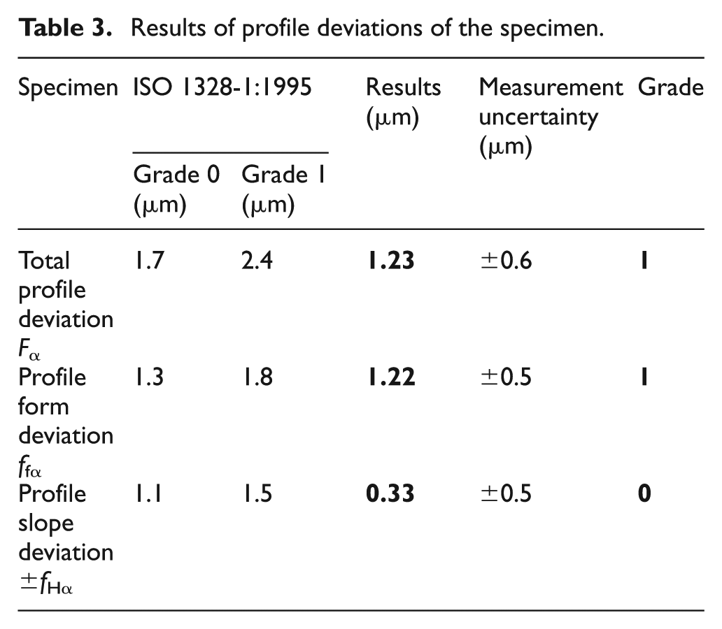
The deviations of the four equispaced teeth are used to calibrate the profile accuracy of the master gear. The test report is shown in Figure 10. Known by the test report, the profile total deviation and the profile form deviation of the specimen are not more than 1.3 µm and profile slope deviation is less than 0.4 µm. Considering the measuring uncertainty of the ultra-precision involute tester, the final results of the profile deviations are shown in Table 3 with the grade 1 and 0 standards defined in ISO 1328-1:1995. It can be seen from the table that the profile accuracy of the specimen achieves grade 1 roundly. So the cam–baffle generating mechanism has the processing capacity of ultra-precision gear involute with grade 1 profile accuracy.
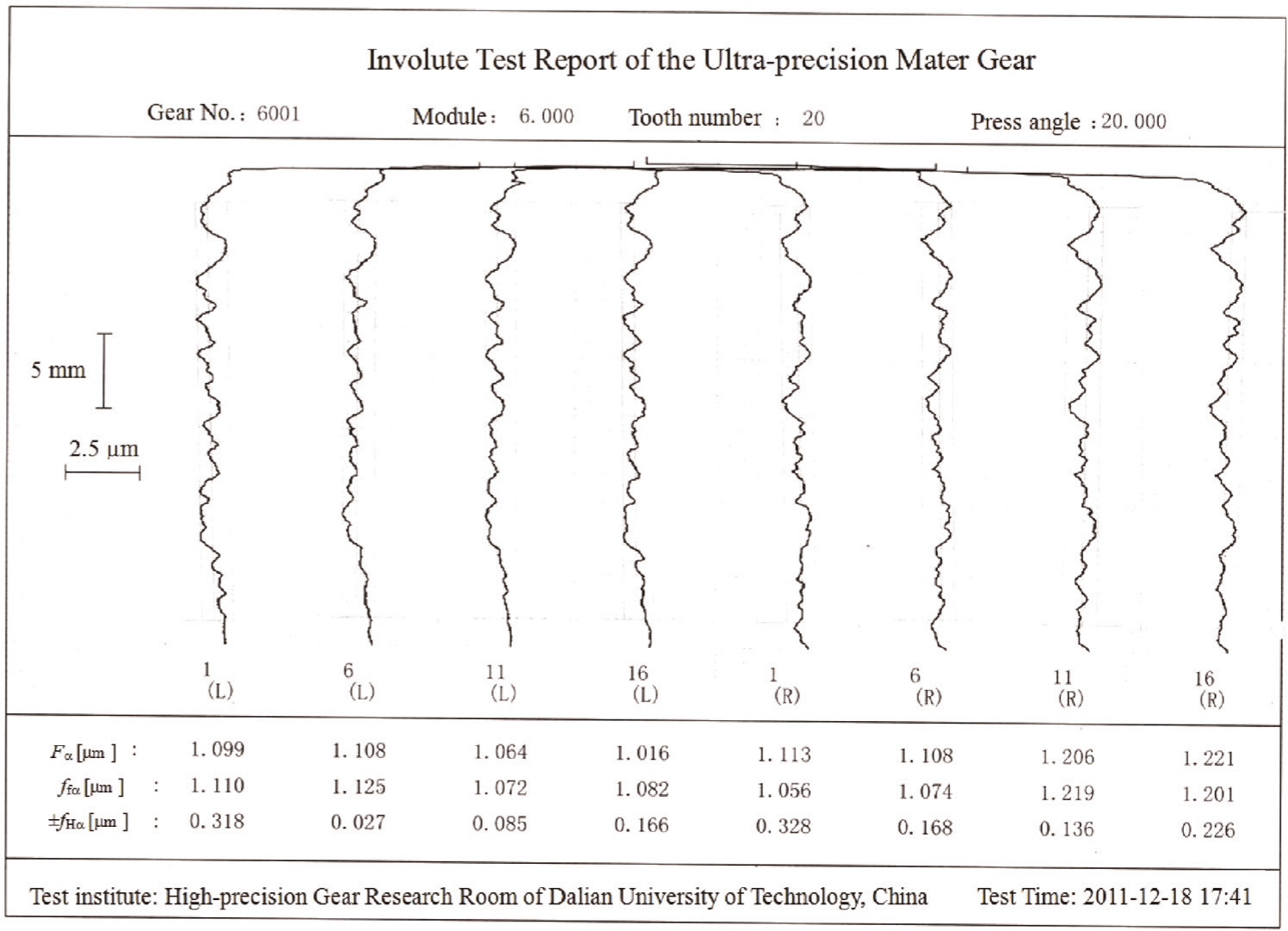
The involute test report of the specimen.
Results of profile deviations of the specimen.
Conclusions
The roller–rail type and cam–baffle mechanical generating mechanism that has little effects of driving accuracy on generating accuracy and less error source matches with the optimal forming principle of the involute. Particularly, the double roller–rail mechanical generating mechanism has higher processing and measuring accuracy of HIA. Considering the double roller–rail involute grinding device with no indexing system, it is suitable for processing the single involute such as the HIA, the involute cam and so on. And the gear grinder with an involute cam–baffle mechanical generating mechanism and precision indexing system can be used in processing UMG and high-precision gear-shaping cutters and gear-shaving cutters in single piece or small batch production. The grinding experiments conform that the double roller–rail involute grinding device has the processing capacity of HIA with submicron-level form profile accuracy, and the cam–baffle gear grinder with high-precision involute cam has the processing capacity of UMG with grade-1 profile accuracy.
Footnotes
Funding
This research is supported by National Natural Science Funds of China (Grant No. 50905026), Fundamental Research Funds for the Central Universities (Grant No. DUT11RC(3)40) and China Postdoctoral Science Foundation (Grant No. 2012M510801).