
Abstract
In the abrasive belt grinding process, there are factors affecting the machining stability, efficiency, and quality. Based on the analysis of the grinding process, the normal force in the contact area between the abrasive belt and the workpiece is a major factor. By comparing constant force and non-constant force grinding, the results imply that keeping the grinding force constant will achieve desired material removal and better surface quality. The phenomenon of over- and under-cutting of the workpieces can also be avoided by a constant normal force. In this article, a controllable and flexible belt grinding mechanism accompanied with a mechanical decoupling control strategy is built and tested. Afterward, a detailed comparison is made between the traditional force-position coupling system and the proposed decoupling control system. The proposed control system suppresses the interference between the position and force control systems. The contact force is directly measured and controlled without detecting the position of other components in the tool system. The complexity of the control system is thereby reduced. Finally, several grinding experiments are carried out. The standard deviation and coefficient of variation of the measured normal force are kept within 0.25 and 0.02, respectively. The experiment results reveal that the mechanical decoupling system performs well in force control compared with the traditional force-position coupling system. In addition, the surface roughness Ra < 0.4 μm, the surface quality of the workpiece is improved significantly with the constant force controller.
Keywords
Introduction
Abrasive grinding is a finishing process employing multiple grain tool with geometrically indeterminate edges for cutting. Common methods of grinding include abrasive belt grinding1–6 and abrasive wheel grinding.7–14 In recent years, as a promising method in grinding, abrasive belt grinding has been widely applied for machining surfaces with complicated geometry like turbine blades. In order to achieve higher machining precision, the material removal rate should be precisely controlled during processing.15,16 The material removal rate is affected by various parameters in the process of abrasive belt grinding, including grinding force, belt rate, and feed-in rate.17–20 Some related study has shown that the constant grinding force combined with the optimal process parameters is quite suitable for belt grinding of complex surfaces.21,22 Thus, in recent years, there are some research works done on how to achieve the desired force control. Cheng et al. 23 investigated the contact force in micro-slot-grinding (MSG) of single-crystal sapphire and installed a dynamometer on a robot to monitor the contact force, but the force control technology was not applied. Zhang et al. 24 proposed a dynamic tool adjustment method based on the geometry of adjacent blades. In Zhang’s paper, the tool system proposed can avoid tool interference and control contact force. Jinfeng Zhang et al. 25 proposed a hybrid passive/active force control scheme for grinding tap with an industrial robot. An abrasive belt grinder with dynamic position adjustment was designed as a passive force control device. In Zhang et al. 24 and Jinfeng Zhang et al.’s 25 article, the contact force is coupled with the position of belt, and the contact force will change as the belt position varies. Duan et al. 26 developed a flexible belt grinding mechanism, and the normal force in this grinding process can be adjusted through the movement of an actuator in this new grinding unit. As the contact force is coupled with the position of the belt, actuators and sensors were installed in each axis of the tool system to control and calculate the position of the belt. The standard deviation and coefficient of variation of the force control result are around 0.6 and 0.025, respectively.
Although these traditional force-position coupled systems can achieve certain control effects, ignorance of the effect of the change of the belt position will lead to an inaccurate result of the contact force control. Also, more actuators and sensors will result in longer delays and affect the control performance.
Taking these problems into account, scholars have proposed some force-position decoupling methods that can effectively and accurately control the contact force. Zhou et al. 27 presented a real-time force-controlled pneumatic compliant tool with self-supplied abrasives, making the abrasives added to the contact area. And, a force-position decoupling pneumatic servo system is applied to control the contact force. However, the decoupling strategy is not mentioned in the article. Hu and Zhan 28 orthogonalized force control from movement control to make the value of the normal force constant. The error of the normal force control is less than 5%. The cutting motion is driven by the rotational motion of the spindle of the computer numerical control (CNC) lathe, and the workpiece is set on the spindle. As a result, the surface of the workpiece must be rotationally symmetric.
Within this article, a mechanical decoupling force control system is proposed to suppress the interference between the position and force control systems. The contact force in the proposed system is directly measured and controlled without detecting the position of other components in the tool system. Only two force sensors are required, without the displacement sensor and angle sensor, to achieve the control requirement. Thereby, the complexity of the control system and the cost of the experiments are reduced. This system is set up on the five-axis series–parallel hybrid machine for grinding, and components with complicated geometric shapes like turbine blades can be machined using a 3-RPS parallel platform (Figure 1). Furthermore, the advantages of keeping the grinding force constant are analyzed by comparing constant force and non-constant force grinding. Finally, several grinding experiments are carried out. The experiment results reveal that the mechanical decoupling system performs well in force control. The standard deviation and coefficient of variation of the measured normal force are kept within 0.25 and 0.02, respectively. In addition, the surface roughness Ra < 0.4 μm, and the surface quality of the workpiece is improved significantly under constant force grinding.
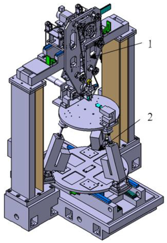
Five-axis series–parallel hybrid machine.
Constant force grinding
According to the Preston empirical equation (1) 29
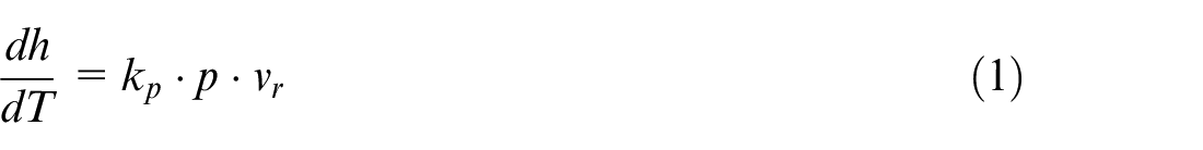
where
Hammann 30 proposed a linear mathematical model as shown in equation (2) to describe how multiple parameters including normal force affect the material removal rate. The situation of the contact region of the workpiece and the belt is illustrated in Figure 2. The grinding tool is composed of the belt and the contact wheel
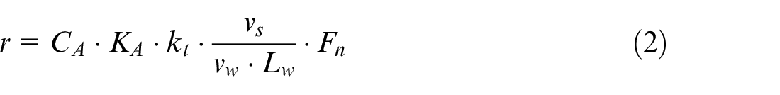
Equation (2) states that material removal rate
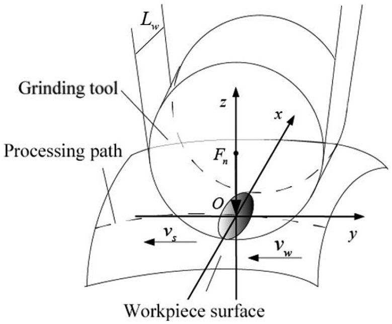
The contact region of the belt and workpiece.
The idea of force control grinding was first proposed by Hahn.
31
In the process of grinding, the workpiece surfaces that are irregular, especially the complicated free-form surface, the material removal volume required is different depending on the positions. Thus, it is necessary to obtain the material removal rate in different processing positions in real time by controlling multiple variables
How to control the parameters to get a better control effect should be discussed. Some related study has shown that the constant grinding force combined with the optimal process parameters is quite suitable for belt grinding of complex surfaces.21,22,26,32 In the process of machining, the change of speed
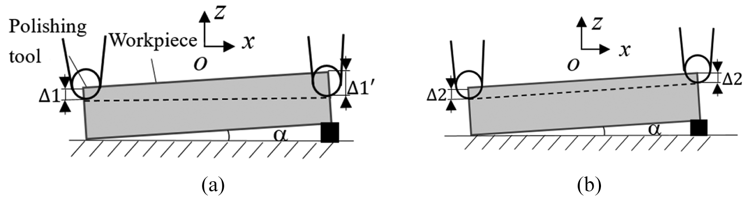
Comparison schematic: (a) non-constant force and (b) constant force.
Xiao and Huang 21 proposed a constant-load adaptive belt polishing (CABP) method. The concave (CCV), convex (CVX), and Y-offset errors of a blade that underwent CABP were, respectively, 36%–24% and 17% less than those of a blade that underwent traditional method without constant force control. Duan et al. 26 investigated the belt grinding process with force control system for blade of aero-engine. The application of a force controller improves the form accuracy from ≥±0.12 to ≤±0.08 mm. Keeping the contact force constant during machining can improve the dimensional precision, but also improve the surface quality. Xu et al. 22 proposed a method of hybrid force-position control combined with PI/PD control in robotic abrasive belt grinding of complex geometries. The phenomena of over- and under-grinding was avoided, and Ra was reduced to half from an average value of 0.744 to 0.335 µm when the force control technology was applied. Zhu et al. 32 analyzed and assessed the robotic belt grinding mechanisms. Experiments of belt grinding with constant contact force are conducted to validate the practicality and effectiveness of force control. The average surface roughness Ra values after belt grinding with force control were reduced to 0.352 µm from the values of 0.641 µm by the grinding without force control. The above analysis and results imply that controlling the normal contact force constant will improve the dimensional precision and the surface quality in belt grinding.
Strategy of normal force control
Traditional coupling control strategy of normal force
Basic structure of traditional force-position system consists of driving wheel, cylinder, force sensor, contact wheel, abrasive belt, and tension device. Figure 4 shows the diagram of the tool system. In this article, we take this basic structure as an example to analyze the control strategy of the coupling tool system for abrasive belt grinding.
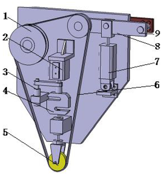
Force-coupled form structure.
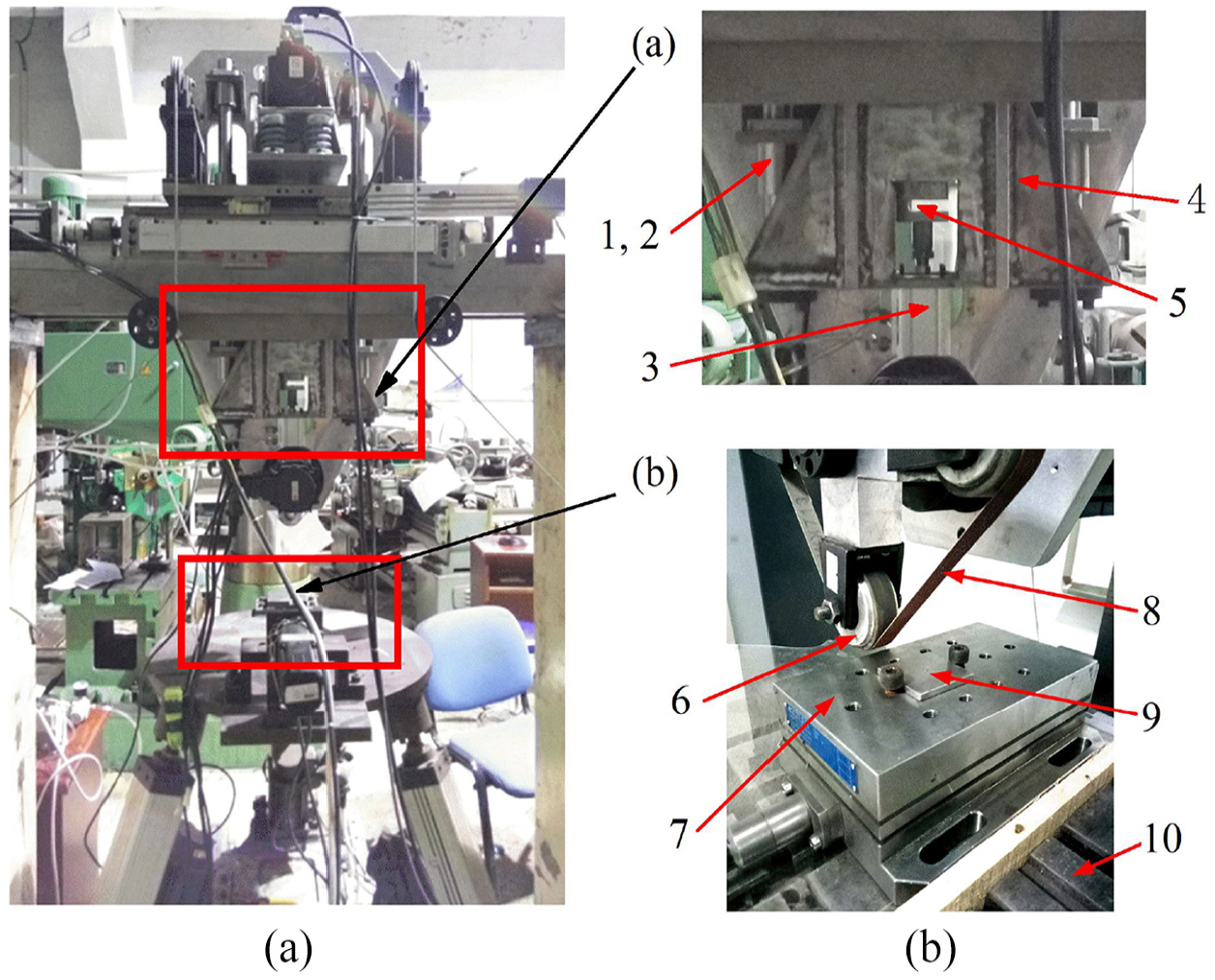
The grinding motor inputs power to the driving wheel 1, drives the contact wheel 5 through the belt 6, and attaches to the surface of the workpiece to remove the material. The tensioning cylinder 7 pushes the tensioning arm 8 to ensure that the abrasive belt is in tension during processing and no slip occurs. The cylinder 2 inputs pressure through the electric proportional valve to provide the grinding normal force and the displacement sensor 3 measures the extension of the cylinder 2.
Figure 5 shows the diagram of the constant grinding force calculation method. This system uses the force-position coupling form to obtain constant grinding normal force. The initial center positions of the contact wheel, tension wheel, and driving wheel are
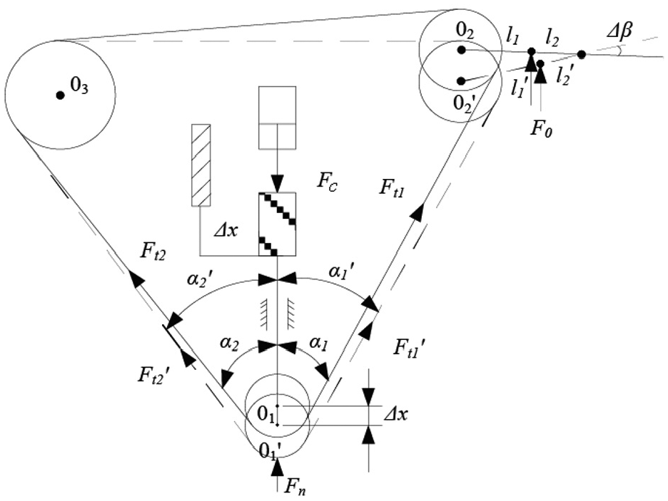
Diagram of grinding force calculation.
According to Figure 5, when the cylinder rod extends

where
After calculation (the derivation process is omitted here), we get the expression of
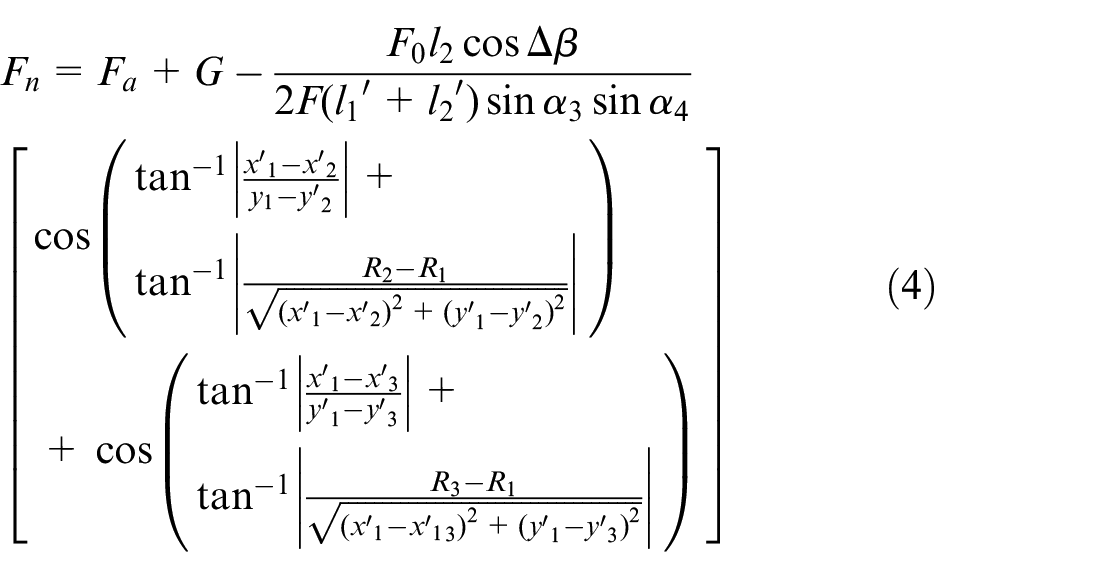
where
As seen from equation (4), the coupling system can realize the constant force control of the normal grinding force. In order to calculate the grinding force, it is necessary to achieve the positions by multiple measurement links, which will result in longer delays and affect the control performance. Therefore, we proposed a novel constant force control method with the mechanical decoupling structure to overcome those limitations.
Novel decoupling control of normal force
Decoupling strategy
Figure 6 shows the schematic diagram of the proposed force control system, which consists of force-output system (Figure 7(a)) and force-detection system (Figure 7(b)). In the force-output system, the output value of the cylinder
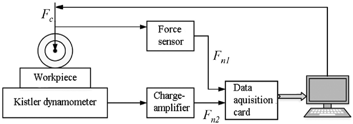
Schematic diagram of the force control system.
Structure of the force-output (a) and force-detection (b) system.
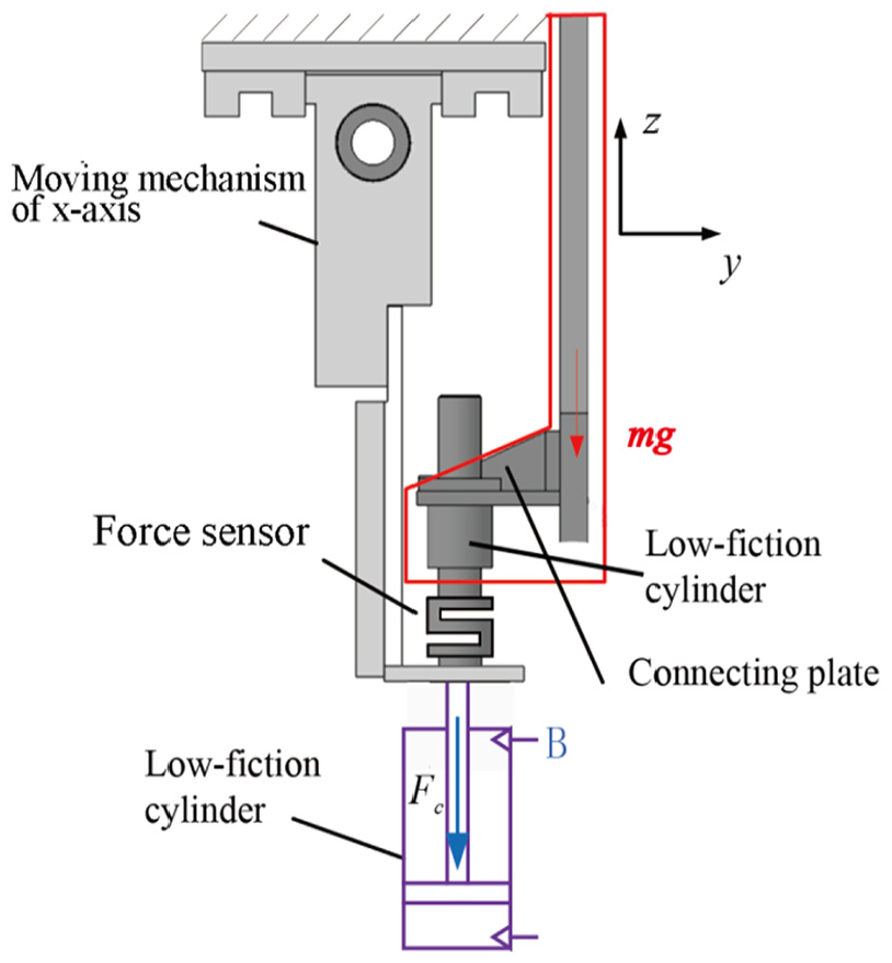
Figure 8 shows the schematic of the mechanical decoupling force control. In the system, the cylinder is extracted from the abrasive belt tool board, and the cylinder thrust acts on the entire tool board instead of directly acting on the contact wheel. As shown in equation (5),

The structure of the force-output system.
The gravity of tool system and the thrust of the cylinder are combined to form the grinding pressure. The force sensor measures the grinding force value and transmits it to the computer terminal in order to adjust it as needed.
The low-friction cylinder is used as the grinding power device to solve the system rigid impact problem and avoid overcutting. When the tool system is used for constant force grinding, the gas with a certain pressure is charged into the cavity A as shown in Figure 8. The difference between gravity of the tool system and z-axis forward thrust constitutes the normal grinding force. The pressure of the cylinder is adjusted to achieve the preset value of the normal grinding force.
Pneumatic servo system
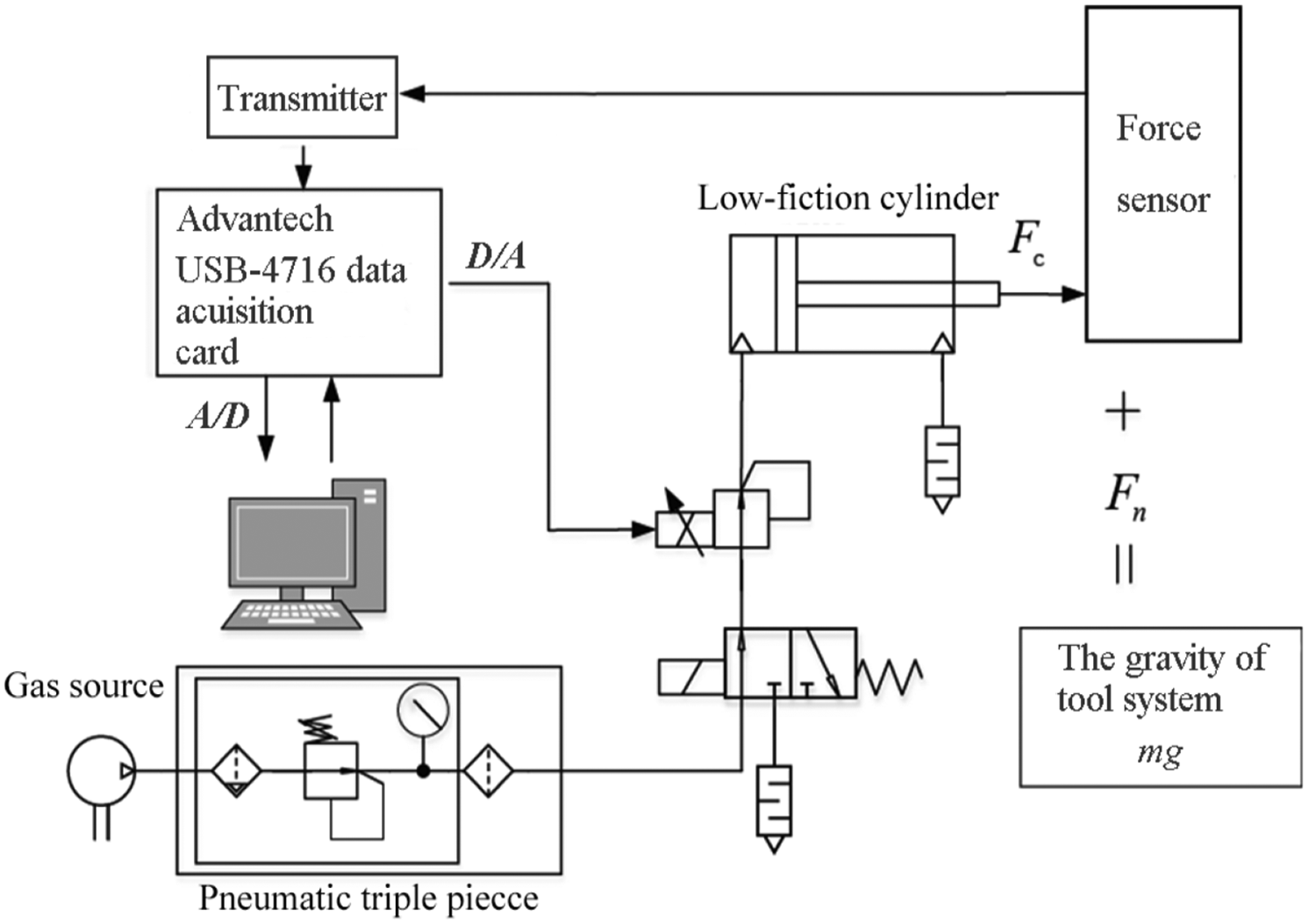
As shown in Figure 9, the pneumatic system is mainly composed of gas source, pneumatic triple piece, electric proportional valve, low-friction cylinder, force sensor, transmitter, Advantech USB-4716 data acquisition card, and host computer.
Pneumatic grinding system diagram.
The gas source pumps working air into the pneumatic triple piece. After being purified, filtered, and decompressed, the air finally enters the low-friction cylinder. One end of the cylinder rod is connected to the force sensor, and the thrust
The value of
Experiments and testing results
Verification of the grinding force control accuracy
Figure 10 shows the graphs of measured data from the experiment when the force inputs
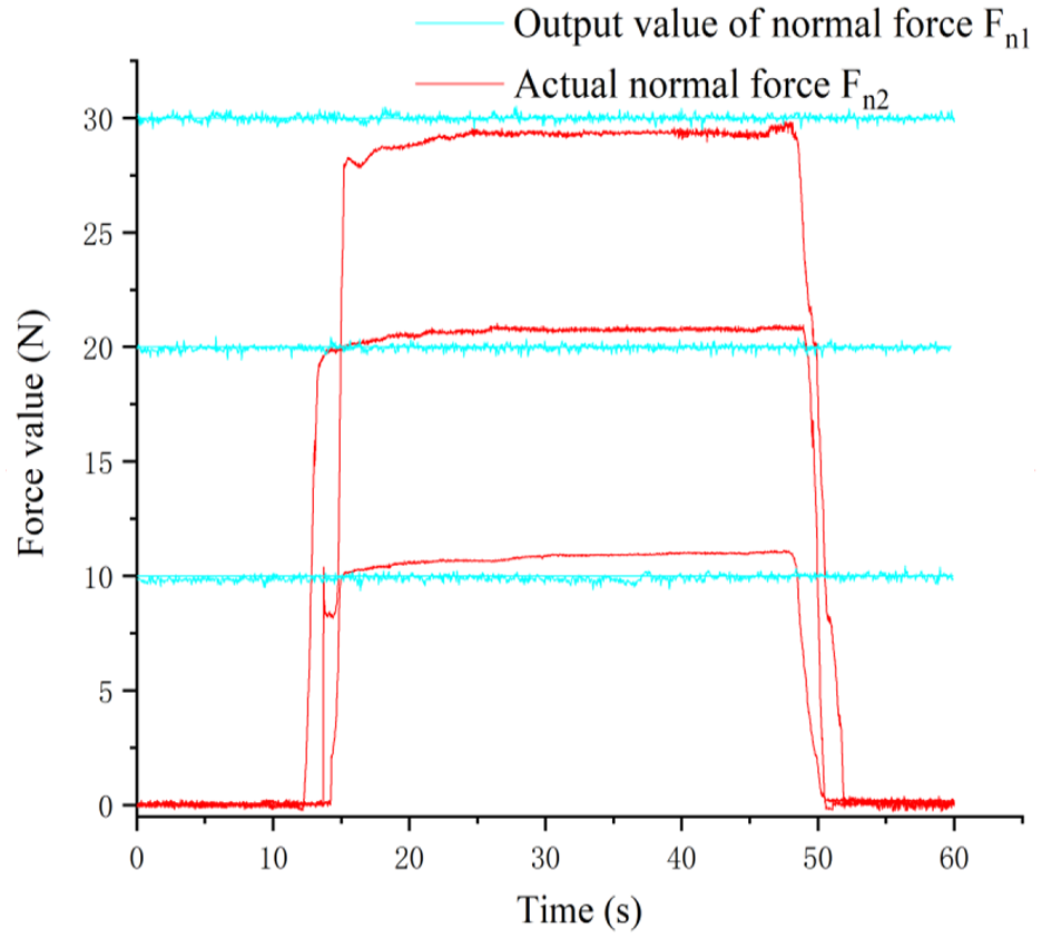
Control performance of proposed system.
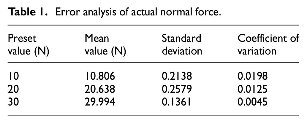
As shown in Figure 10 and Table 1, the errors between preset value and measured value are less than 1 N, and the standard deviation and coefficient of variation is kept within 0.25 and 0.02, respectively. The result reveals that the force-position decoupling system has a good performance in controlling the normal force.
Error analysis of actual normal force.
Experiments on constant force grinding effect
In order to prove the material removal effect of this force control system, an experimental scheme was designed (as shown in Table 2). The experimental parameters
Design of experiments on belt grinding.
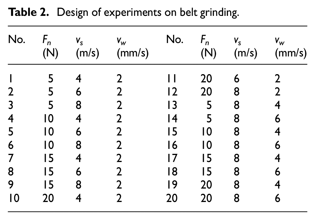
Figure 11 demonstrates the overall evaluation of the effects of the above three belt grinding process parameters on the removal depth. Figure 11(a)–(c) shows that the material removal depth is positively related to
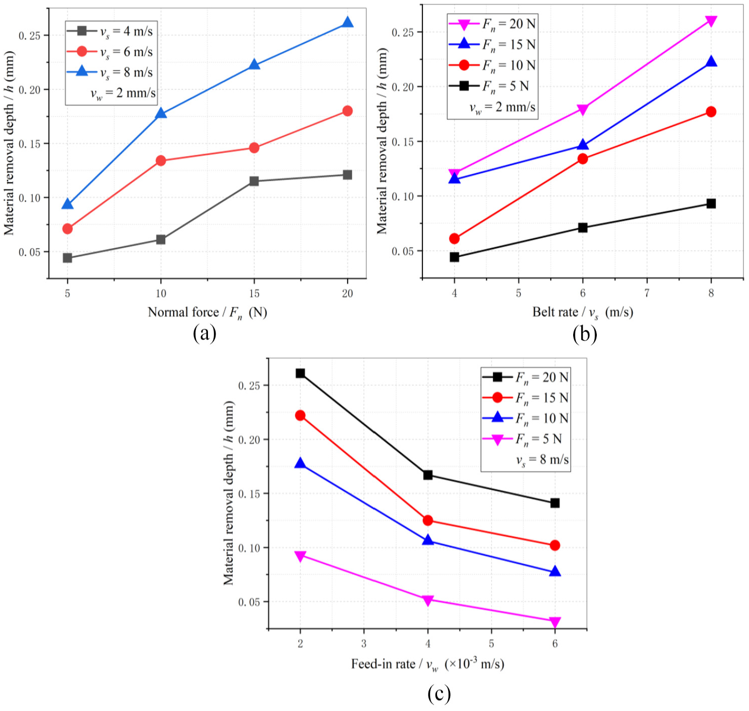
Effects of the normal force (a), belt rate (b), and feed-in rate (c) on the grinding depth.
Surface quality after grinding
Surface quality is usually used as an indicator to evaluate the quality of grinding. The evaluation criteria of surface quality are usually evaluated by surface roughness. In order to verify the machining quality of the proposed force controller, two sets of experiments are carried out. Two sets of test workpieces were ground without and with the force controller, respectively. The experimental materials include C45E4 workpieces, a polyurethane contact wheel, and a 15-mm-wide abrasive belt whose type is GXK51. The grinding speed
A 3D microscope VHX-900 was used to measure the surface topographies. As portrayed in Figure 12, compared with the surfaces before grinding and ground without force control, the surface is smoother under constant force control grinding.
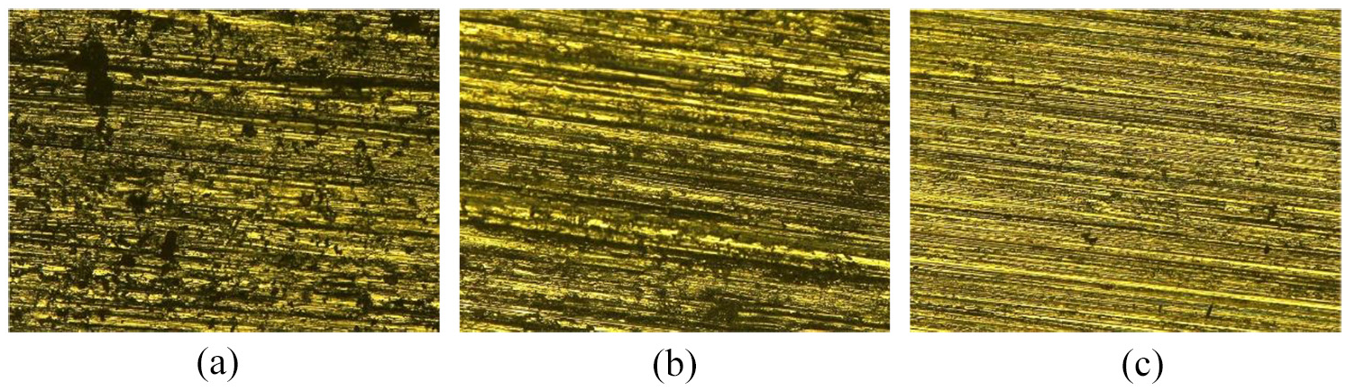
Surface topographies: (a) before grinding, (b) without force controller, and (c) with force controller.
Figure 13 shows the surface roughness results of the above workpieces, measured by the Surface Roughness Tester Links-2207. In this experiment, Ra is used as the evaluation index of surface roughness. The results indicate that the machining quality improves significantly after grinding with proposed constant normal force controller. Compared with the process of grinding without force control, the Ra reduces from 0.7387 to 0.3767 μm. This has satisfied the machining requirements of components including blades in the manufacturing process.
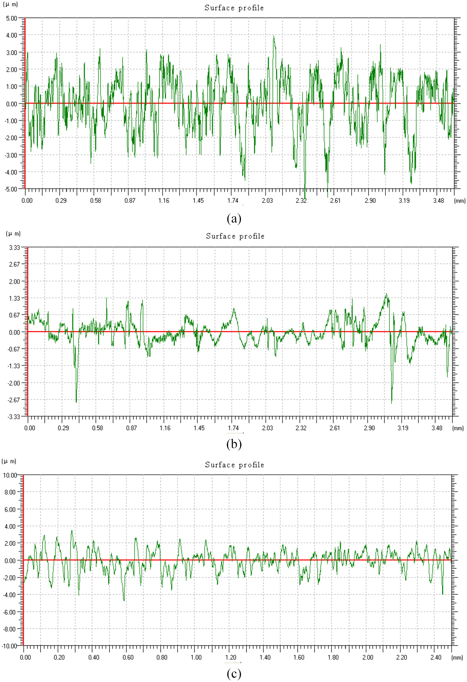
Surface roughness: (a) before grinding, Ra = 1.2707 μm; (b) without force control, Ra = 0.7387 μm; and (c) constant force control, Ra = 0.3767 μm.
Conclusion
For this article, the advantages of constant force grinding are discussed by comparing constant force and non-constant grinding. The results demonstrate that keeping the grinding force constant will achieve desired material removal and better surface quality. The phenomenon of over- and under-cutting of the workpieces can also be avoided by a constant normal force. In order to achieve constant force control, a mechanical decoupling tool system is designed and tested. The contact force is directly measured and controlled without detecting the position of other components in the tool system. The force control is decoupled from the motion control. The complexity of the control system is thereby reduced. By experiments, it was proved that the proposed tool system can control the normal grinding force consistently and with accuracy. The outcomes also prove that the proposed constant force control system with a decoupling strategy has positive results in controlling the material removal rate and improving the surface quality of the workpiece.
Footnotes
Appendix 1
Declaration of conflicting interests
The author(s) declared no potential conflicts of interest with respect to the research, authorship, and/or publication of this article.
Funding
The author(s) disclosed receipt of the following financial support for the research, authorship, and/or publication of this article: The research work was supported by the National Natural Science Foundation of China (grant number 51135006).