
Abstract
For using ultrafine-grained metals and alloys in industry, further machining sequences and studying their possible effects are necessary to attain these products in their ultimate dimensions. In this work, the machinability of ultrafine-grained pure copper and the corresponding coarse-grained counterpart investigated systematically. The results showed that the processed copper could be machined as efficiently as its initial one. Also, the machining of the Cu sample with the polycrystalline diamond tools requires much less force than tungsten carbide tools. The produced cutting forces were smaller for the processed copper as compared to the initial copper. Also, similar tool wear mechanisms were detectable for the copper specimen before and after the process. Chip morphology altered less through the machining, and the surface quality enhanced during machining the ultrafine-grained copper. Eventually, the polycrystalline diamond tool increased the surface roughness of initial and processed specimens since it caused less than 50% roughness compared to the tungsten carbide tool.
Introduction
Machining can be defined as the process of removing material in which a specimen is placed into a lathe or mill while a cutting tool is used to cut the shape of the component. Machinery has been in operations for more than 200 years, and although many new production methods have been introduced in recent years, this process still serves as a significant part of manufacturing.1,2 It is generally accepted that two kinds of metal cutting studying schemes have existed. One focuses on knowledge on how to do economic machining, and the other deals with the issues of cutting edge through cutting and why it happens. Machinery has been widely studied 200 years before. However, the base of main mechanics of metal cutting chips was revealed during 1930–1950 (golden age). 3
A study on machining efficiency has been grown in recent years because of the development of high-level cutting and sample materials in the company of completely definite machine control systems.3,4 Lathes are more commonly used in machining investigation since the related cutting mechanics are available to the model, because of the uninterrupted cutting process and the need for low process variables. In turning lathe, according to Figure 1, the independent variables include feed rate, cutting depth, and cutting speed. The cutting speed defines either the sample rotation speed or the sample linear tangential speed at the tooltip. The cutting depth (depth of cut) describes 50% of the diameter difference between the processed and initial surfaces. Also, the linear distance that happens during a sample rotation is assigned as the feed rate.2–4 On the other hand, bio-machining of copper samples which is based on the metallic material removal by solubilization through pure chemical reactions in solution has been studied extensively.5–7 In this regard, the effect of the main parameters affecting the continuity of the process has been investigated during the incubation, bio-machining, and regeneration phases.
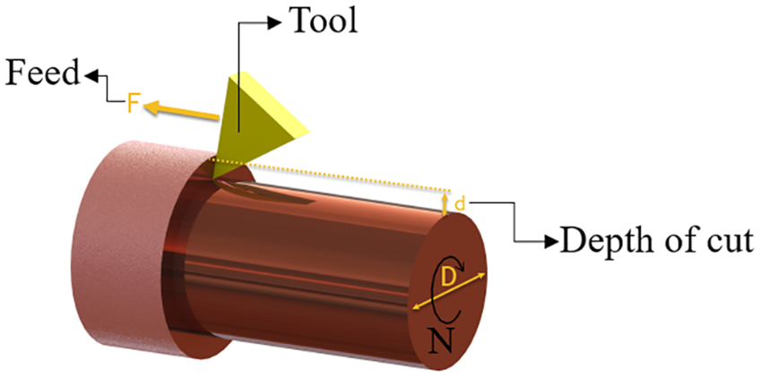
Important turning processing variables.
Several factors that influence machinability are the material’s nature (mechanical and microstructure properties), tool features (strength and geometry), and machine characteristics (accuracy and required load).8,9 To evaluate material machining, cutting forces, chip morphology, surface roughness, and tool wear appear to be influential parameters. The mentioned features are not acting independently of each other and may lead to alterations in each other. Besides, some of these machining effects are significant compared to others. Previous studies have shown that it is the most machinable material that provides the fastest possible removal of materials with a satisfactory finish and economical cost. 10 Given the wide range of definitions for machining, sample machining is measured typically by comparing it to other materials.2,11
Due to the recent use of improved materials due to their superior strength, suitable ductility, low weight, etc., the demand for their use in the application has increased. 1 Therefore, many advanced materials have the potential to be used in engineering, but there is a gap between the frontier of knowledge and industry to implement these materials. For the newly made materials to take shape in their overall dimensions, additional machining analysis is needed.
The current proliferation of ultrafine-grained (UFG) metals and alloys with double strength compared to their coarse-grained (CG) counterparts, has generated much attention in this field of research. There are several methods to produce UFG/NS materials. Unlike UFG/NS materials made from consolidating atoms/nanoparticles, materials fabricated by severe plastic deformation (SPD), a process of imposing large shear strains to a specimen, are produced with superior strength, acceptable ductility, and suitable tribology behavior.12,13 Also, significant large specimens can be built made from bulk without internal porosity, making processed SPD specimens the most popular type of material for industrial use among other UFG/NS materials.14–17 Based on these methods, there are different SPD methods. The outstanding behavior of these materials is only related to their defect structures. In addition to the significantly smaller grains in the order of 200–600 nm, there are many dislocations and subgrains throughout the structure that help to block slip and thus improve the strength of the material.18–21
So far, various SPD methods have been proposed for SPD that let a specimen plastically deformed with no considerable alteration in size and shape.21,22 Two of the most successful are high-pressure torsion (HPT) and equal channel angular pressing (ECAP).13,23 Other methods include multi-directional forging, 19 accumulative roll bonding, 24 equal channel forward extrusion, 12 constrained groove pressing, 25 twist extrusion, 26 planar twist channel angular extrusion, 27 etc. The HPT process provides UFG/NS metals and alloys, by which a thin disc-shaped specimen under high hydrostatic pressure is subjected to torsional straining. Also, ECAP is a method in which a specimen located on the entrance channel is pushed into the exit channel leading to inducing a high amount of shear plastic strains (Figure 2). Although the HPT method can produce specimens with the size of grains smaller than ECAP, ECAP has the highest capability for industrial application because of the capacity to make comparatively large bulk specimens containing homogeneous grains with relative ease.28,29
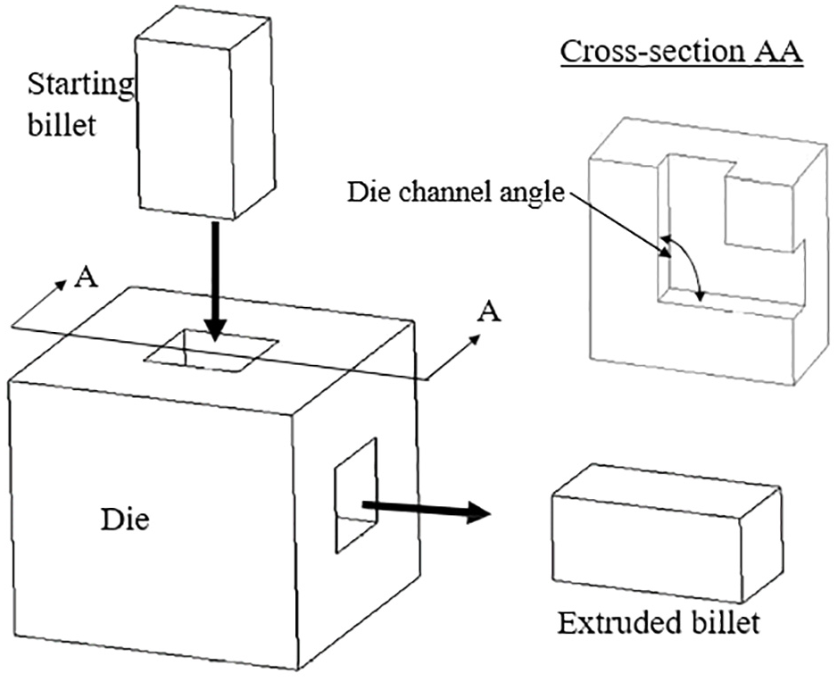
The schematic illustration of ECAP process.
Because the generated heating during the fabrication of UFG/NS materials can alter their microstructure, it may be difficult to obtain a device for shaping these materials in their overall size. Since machining is a process of heat-dissipating, the thermal stability of ultrafine-grained and even nanostructured metals and alloys should be thoroughly examined so as not to damage the corresponding superior behavior.30–33
Recently, thermal research has been done on SPDed copper (Cu) to find out where the annealing process takes place and how it changes at this temperature. Two distinct annealing experiments have been performed for tension and compression on ECAP Cu. 28 It was found that annealing the Cu specimen at 500°C for 2 h reduces the ultimate tensile strength with a decrease in the modulus of elasticity. Also, at less annealing times and temperatures during the compression of ECAPed Cu, the strength decreases, but the modulus of elasticity will be much higher compared to the fully annealed specimen. Accordingly, shorter annealing does not cause subsequent grain growth but leads to recovery of the grain boundary defect structure.
Measuring how this material efficiently can be related to machining through the right tools and cutting parameters.10,34–36 Elkaseer et al. 37 investigated the machining behavior of metallurgically and mechanically modified copper samples at the micro-scale. They reported that grain refinement leads to the minimum chip thickness and a high surface finish. For assessing the undiscovered material machinability, process-dependent variables are usually examined and compared with the identified materials. When it comes to calculating the machinability of UFG/NS materials, comparing these findings with CG materials would be a logical choice, because they are made of the same material but still show different physical behavior.11,38–40
This research aims to study the machinability of UFG/NS commercially pure Cu in machining. These materials were conducted using the ECAP process to reach UFG/NS conditions. While many studies are available on traditional Cu machining, there is still nothing to do with cutting efficiency in machining these materials after processing by ECAP. Therefore, for the evaluation of ECAPed CP-Cu machining, generated cutting forces in three dimensions, chip size and morphology, tool wear and mechanism, and surface finish during machining were examined and compared with CG counterparts.
Materials and methods
The ECAP processing of pure Cu applied to this study consisted of four pressing passes at ambient temperature by route BC through a 90° channel angle. The grains refined from 80 µm to 320 nm deformed by the ECAP method. Also, the deformed Cu showed a yield and ultimate tensile strengths of 340 and 460 MPa compared to the coarse-grained pure Cu with a yield and ultimate tensile strengths of 51 and 256 MPa, respectively. Furthermore, the hardness magnitude of pure copper samples in the conditions before and after the ECAP process is 43.1 and 135.1, respectively.
The obtained UFG Cu specimens after the ECAP process were turned into round shapes to fit inside the collet. Therefore, the square specimens, which were 25.4 mm × 25.4 mm, were machined to 23.6 mm, as shown in Figure 3(a). Round specimens were taken for further machining with low amounts of feed rate and cutting depth. Also, they reduce the cooling fluid to decrease any heat effects on the specimen, which can cause microstructural changes. Note that the length of the specimens (140 mm) was not impacted by this process before machining. In addition, polycrystalline diamond and tungsten carbide tools were selected for this comparative investigation.
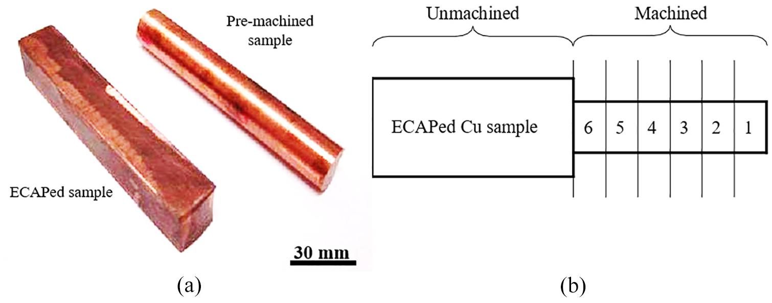
(a) Preparation of pure ECAPed Cu specimens for further research and (b) schematic representation of sample preparation for inspection with scanning electron microscopy.
To clear the application cutting conditions for both Cu specimens, different depths of cuts, feeds, and cutting speeds were examined on ECAPed specimens to obtain the optimal surface level. Accordingly, the best possible surface finish by the tungsten carbide tool was as follows: 2 m/s cutting speed, 0.2 mm/rev feed rate, and 0.04 mm cutting depth. Such a small cutting depth was preferred since it allows the utmost pass numbers on each specimen with the protection of the material. At first, 80 passes from the free end of the Cu specimens were cut (pieces 1–3 in Figure 3(b)). Afterward, another group of 80 passes was prepared (pieces 4–6 in Figure 3(b)). Generated cutting forces obtained, produced chips gathered, and the flank wear measured repeatedly for each Cu specimen. Also, machinery testing halted after 160 passes.
Subsequently, all cutting processes were performed on the CNC lathe. The 3D cutting forces during the machining were computed through the Kistler dynamometer. The Dynaware software was used for analyzing the ultimate force signals. Additionally, optical microscopy and surface profilometer were utilized to investigate the wear patterns and mechanisms of the applied tools formed on parts of the rake face and flank zones. To study with scanning electron microscopy, these sections were polished. The employed etchant for specimens was a normal solution of 10 g of iron nitrate, 20 ml of hydrochloric acid, and 75 ml of water. Then, the specimens were washed in water and dried in air. The chip morphology was also studied during cutting. A surface profilometer was utilized to analyze the surface finish of the turned specimens. Afterward, surface images were used to obtain Ra on the selected machined surface. In addition, an electrical conductivity test was measured under the ASTM E1004 through the eddy current method. Note that the surface of each sample was mechanically polished to eliminate any contaminations before the measurement. Also, the electrical conductivity was denoted as a relative value of the International Annealed Copper Standard (%IACS).
Results and discussion
The generated cutting forces are usually related to the tool’s material and geometry, and the physical behavior of the specimen. Figure 4 provides generated forces (Fx for the tangential force, Fy for the thrust force, and Fz for the feed force) for both copper conditions at different turning times through tungsten carbide and polycrystalline diamond tools. As is understood, machining with tungsten carbide is required for both Cu specimens to be about five times the cutting forces of a polycrystalline diamond. According to the cutting situation for machining UFG Cu with both tools, the tangential force is the predominant force. Although there is much higher yield strength of the UFG Cu, the required forces in tangential direction during machining UFG Cu are about 6–9 N lower than CG Cu; see Figure 4(a) and (b).
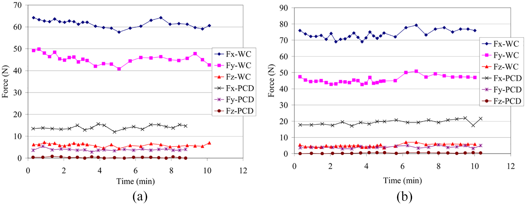
Cutting forces during machining by means of polycrystalline diamond (PCD) and tungsten carbide (WC) tools:(a) UFG Cu and (b) CG Cu.
According to comparative experiments in Cu cutting through polycrystalline diamond and tungsten carbide tools, no significant difference was seen in the wear pattern in the machining of both conventional and UFG Cu specimens through the same type of tool. Cutting depth grooving/notching was seen as the main wear pattern in CG and UFG Cu cutting through a tungsten carbide tool (Figure 5(a)). As shown in Figure 5(b), no apparent abrasive wear was seen in the CG and UFG Cu machining by the polycrystalline diamond tool at the studied cutting time. However, flank wear was detectable as the predominant wear pattern. Also, Figure 6 represents the progress of flank wear in machining the deformed and initial Cu specimens with tungsten carbide and polycrystalline diamond. Moreover, the length of flank wear for the tungsten carbide tool was measured according to the notch length of the flank face.
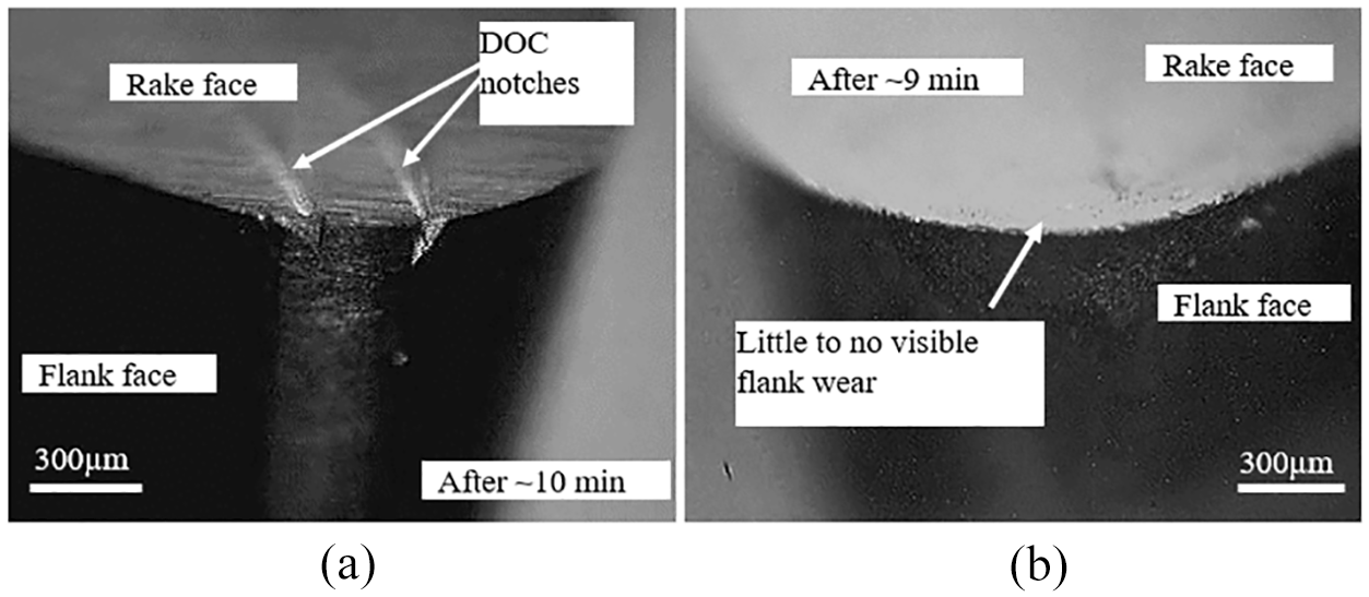
Observation of wear patterns at the initial and deformed Cu machining using two types of tools: (a) tungsten carbide (WC) and (b) polycrystalline diamond (PCD).
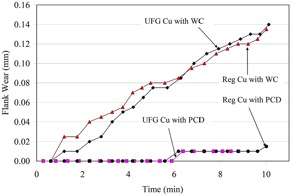
Flank wear progression in UFG Cu machining by means of two types of tools including tungsten carbide and polycrystalline diamond.
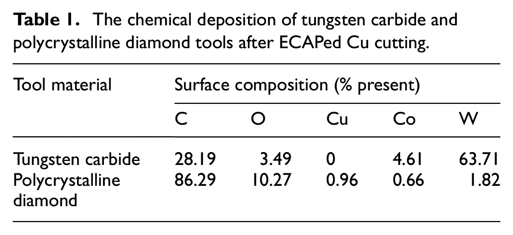
To further find out the wear mechanism during two types of used tools, energy dispersive spectroscopy (EDS) analysis was applied to determine the percentage of different elements and residual materials in the tool rake face. The results are listed in Table 1. By machining UFG Cu specimens, a quite little copper trace (0.95%) was detectable on the rake face of the diamond tool. The carbide tool did not provide any traces of Cu after the machining experiment.
The chemical deposition of tungsten carbide and polycrystalline diamond tools after ECAPed Cu cutting.
As is observed in machining by tungsten carbide tools, the cutting depth grooving is associated with excessive heat production in the interface of the tool chip. This wear pattern, which is often caused by abrasion, is usually as cutting soft metals like Cu.11,39 This cutting depth grooving wear pattern has a much lower amount of thermal conductivity (90 W/mK) in comparison with the polycrystalline diamond tool (540 W/mK). As known, most of the energy converts to heat during turning due to the plastic deformation and friction. In this regard, around 75% and 25% of the generated heat dissipates into the chip and a turning tool, respectively. 8 Since the rate of heat transfer of the chip is more prominent in the edges than the center, more thermal energy transfers from the chip edge to the surface of the tool. The produced hot chips are fabricated through the carbide tool due to the low thermal conductivity, which is rubbed abrasively on the rake and flank faces of the applied tool. This issue finally creates cutting depth grooving that is created by abrasion equal to the width of the produced chip. Far from the tungsten carbide tool, no cutting depth grooving was recognized for polycrystalline diamond tools. In addition to being more thermally compatible with tungsten carbide tools, polycrystalline diamond tools have the following features that are particularly attractive from the wear resistance point of view. First of all, diamond has the extremely hard nature. Generally, a diamond tool has 60–90 times more tool life than a tungsten carbide cutting tool. In the second step, a tungsten carbide tool (Ra = 251.4 nm) presents a much softer and more polished face than the polycrystalline diamond rake face (Ra = 55.9 nm). This issue consequently decreases the friction of the tool chip. So, the obtained low friction feature makes the polycrystalline diamond toolless prone to wear.
As mentioned above, Table 1 lists information about the element percentage of tungsten carbide and polycrystalline diamond tools. During conventional Cu machining by tungsten carbide tools, residual Cu particles were found along with the tool rake and flank faces. 38 This issue makes an adhesion wear mechanism in conventional Cu machining using tungsten carbide tools. The adhesion is due to the breakage of the hot welded joints inside the Cu chip and the tooltip,38,39 so the welded copper bits are cut on the surface of the tooltip. The mechanism of adhesion wear rarely occurs independently of other mechanisms. Therefore, both adhesion and abrasion are two fundamental mechanisms of wear in conventional pure Cu cutting using the tungsten carbide tool. Note that since no trace of Cu was observed on the face of the tool rake, diffusion cannot be a wear mechanism in initial Cu machining by the tungsten carbide tool.
Given that traces of Cu have been found in the polycrystalline diamond tool during machining the initial and deformed Cu specimens, and the polycrystalline diamond tools have not been able to detect any detectable micro welds due to adhesion, the diffusion instead of adhesion can be the predominant wear mechanism during turning Cu specimens. This observation coincides with a previous report on the assumption of diffusion wear mechanism during Cu machining by means of a diamond tool.11,38 Also, the percentage of Cu tracking in CG Cu was higher than in UFG. This is related to the fact that the cutting forces in CG Cu machining were higher than those of the UFG Cu. Lower cutting forces for the UFG Cu indicate less heat generation. Because the diffusion rate depends on the temperature so that the low temperature results in a low rate of diffusion. This causes a relatively lower Cu percentage in the applied tool during UFG Cu machining.
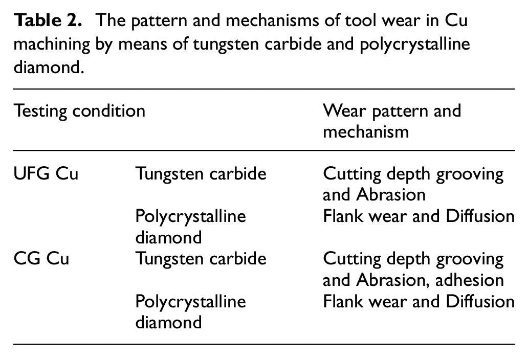
As can be mentioned in Table 1, the polycrystalline diamond tool gathered additional Cu on the tool rake face compared to the tungsten carbide tool in UFG Cu cutting. However, as is observed that the polycrystalline diamond tools gathered much less Cu on the tool rake face than tungsten carbide tools in conventional Cu machining. This significant increase of Cu by means of the tungsten carbide tool is associated with the clear adhesive wear in conventional Cu machining, and the adhesive wear is accounted for a total increase of 4.69%. Based on this, the patterns and mechanisms of tool wear for initial and ECAPed Cu machining are given in Table 2.
The pattern and mechanisms of tool wear in Cu machining by means of tungsten carbide and polycrystalline diamond.
Despite the chip size and shape kept unchanged during UFG and CG Cu machining, the difference in chips during machining by tungsten carbide over polycrystalline diamond was considerable. Figure 7 shows chip images by means of optical and scanning electron microscopes taken in UFG Cu machining. Although not pictured, conventional Cu exhibited similar chip properties. As known, the chips generated during machining with the tungsten carbide occur continuously with burrs (about 1 mm2 cross-section) at every 2–4 cm on the surface of chip-free. The mentioned process contrasts with the complex continuous curled chips fabricated by polycrystalline diamond tools that do not create any burrs. According to the images for the tool and free sides of the chip, flat surface and slightly rough face can be respectively distinguishable. The polycrystalline diamond tool has made continuous tightly curled chips. Because the morphology of the chip has not been altered during all experiments, tool wear has no clear impact on chip size and shape change.
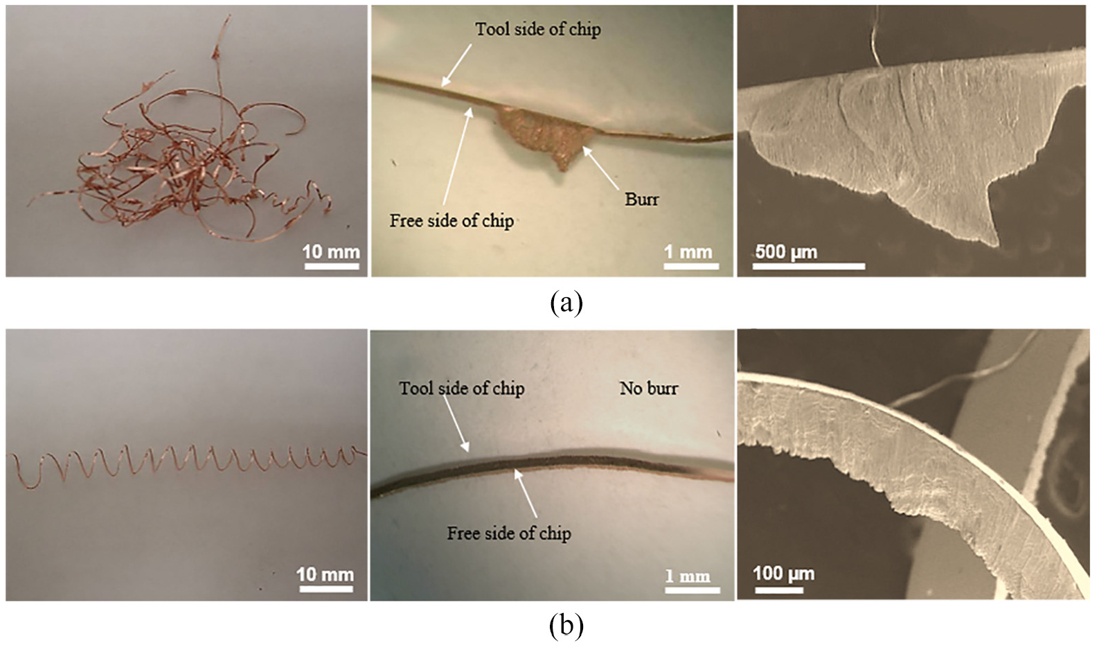
Macrographs and images of scanning electron microscopy of UFG Cu chips in machining with tungsten carbide (above row) and polycrystalline diamond tools (below row).
Through the tungsten carbide tool, chips with burrs were discovered during the turning initial and ECAPed Cu. This event is dedicated to overheating in the interface of the tool chip during turning. The produced and stored thermal energy in this material leads to the chips for clustering and melting in both shear regions of primary and secondary. When the clusters change to coarse and unstable, they break and most of the content is taken away by the chip. This event is a bit like the built-up edge unless the burr in the chip-free side deposits on the side of the tool. Some parts of the burr can be pushed into the tool and the sample, making a chip adhere to the machined specimen. Therefore, this issue decreases the quality of the surface and the life of the tool. Due to the intense strained of the burr, the burr embedded chip can assist to propagate groove production in the tool faces of the tungsten carbide. The enlarged burr micrograph in Figure 7 (above row), indicating its acute and sharp feature. The absence of burrs produced by polycrystalline diamond tools can be described by the higher thermal conductivity of polycrystalline diamond tools, which leads to a better tendency of the heat generated away from the interface of the tool-chip during cutting. The chips with tightly curled nature made from polycrystalline diamond tools with suitable lubrication of rake face come with a little coefficient of friction.
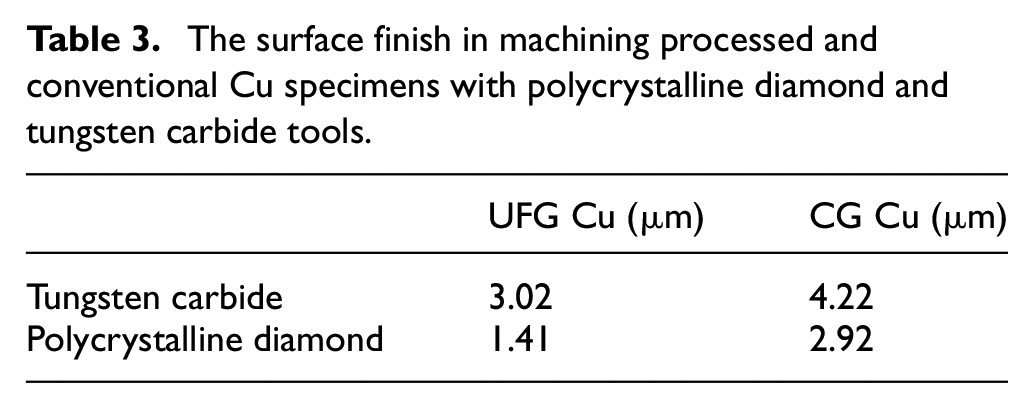
The average surface roughness value was obtained through a profilometer. As stated earlier, the profilometer permits you to take images of the surface, and Figure 8 represents the differences between the conventional and UFG Cu machined through two tool materials. It can be said that the machining marks from the two specimens display similar feed rate distances. A review of the surface roughness taken during machining is given in Table 3. UFG Cu machining with polycrystalline diamond tools was observed as the most optimal roughness level. It can be concluded that the polycrystalline diamond tool produced nearly 50% amount of the roughness (1.41 µm) in comparison with the tungsten carbide (3.02 µm), and makes it more suitable if a proper surface finish is needed. Similar results have been achieved in the study by González et al.41,42 on the thermoresistant superalloy of Inconel718 during milling and grinding.
The surface finish in machining processed and conventional Cu specimens with polycrystalline diamond and tungsten carbide tools.
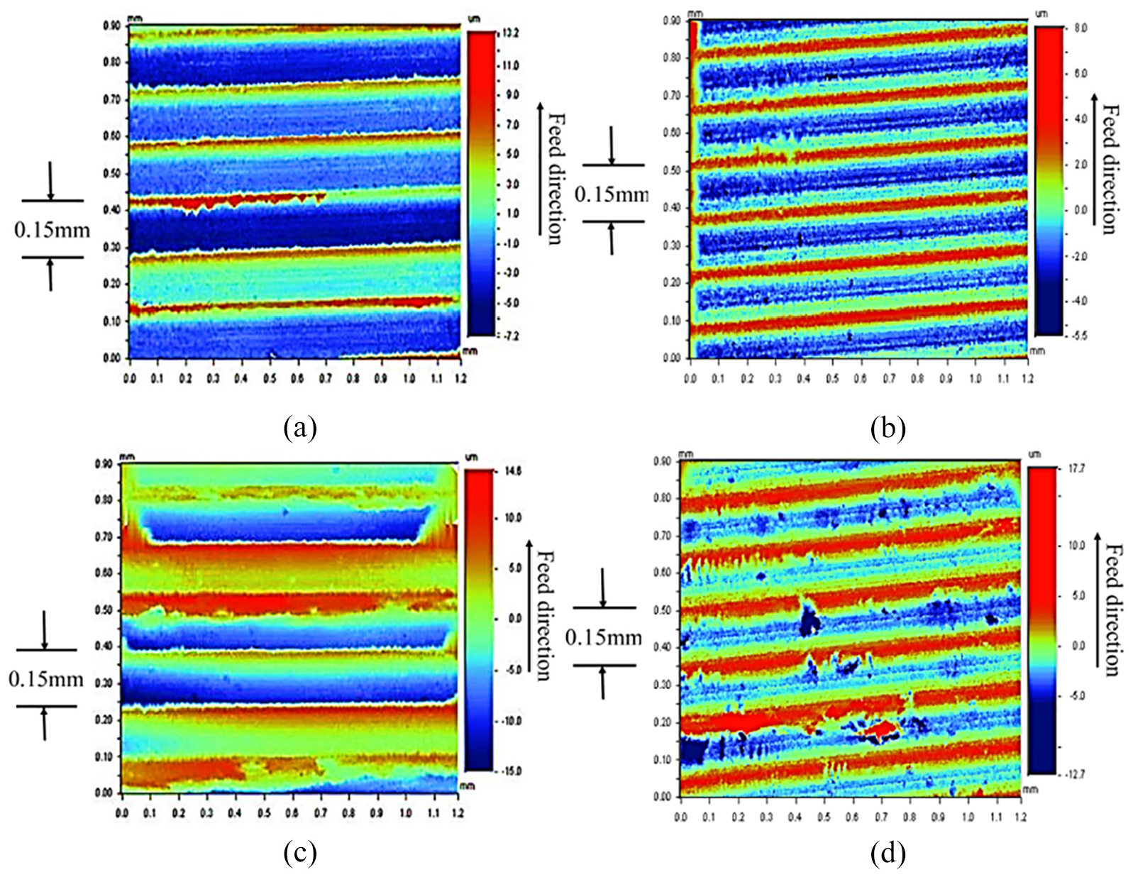
Surface information of machined UFG Cu through (a) tungsten carbide and (b) polycrystalline diamond tools and machined CG Cu made with (c) tungsten carbide and (d) polycrystalline diamond tools.
Pure Cu is generally considered to be a challenge for machining in general due to its suitable elongation and the large frictional forces inside the chip and tool. The final surface finish is usually medium and week in comparison with the other pure metals. After ECAP processing, the roughness of the Cu specimen may still be relatively high. In addition, due to its high hardness behavior and wear resistance, the diamond tool is recognized to provide much better roughness on the surface through nonferrous metals’ machining. During machining both initial and deformed Cu specimens, the polycrystalline diamond tool produced half the roughness of the tungsten carbide tool, and if necessary, the required quality makes the polycrystalline diamond tool more suitable. The UFG Cu specimen produced a better surface finish through machining by both tools. This agrees with this finding that the cold-working of materials increases the integrity of the surface after turning. To obtain a uniform level of surface finish using polycrystalline diamond tools, smaller feed rates, and larger radius tools must be chosen.
The pure copper in the initial condition has an electrical conductivity of 99.8% IACS, while the grain refinement by the ECAP process makes a decrease to 92.6% IACS. It indicates a decrease of about 7% IACS. The same behavior has been reported in the refs.43–45 This phenomenon is related to electron scattering due to structural defects.
Summary and conclusions
A comparative analysis was performed to study the machining ability of UFG Cu during machining through the polycrystalline diamond and tungsten carbide tools. Afterward, generated cutting forces, tool wear and mechanism, and surface finish were analyzed before and after the machining. The main conclusions can be drawn as follows:
Cu specimen machining with the polycrystalline diamond tools showed that it requires much less force than tungsten carbide tools. Conventional Cu machining with tungsten carbide tools confirmed its poor performance as a function of required forces.
In UFG Cu machining, cutting depth grooving and abrasion were known as the wear pattern and mechanism of the tungsten carbide tool, also the flank wear and diffusion were known as the wear pattern and mechanism of the polycrystalline diamond tool.
The chips produced by means of the tungsten carbide tool revealed heat-induced burrs occur commonly alongside the chip for the initial and ECAPed Cu. The mentioned burrs raised tool wear and damaged the surface of the specimen. The before-mentioned burrs were not recognized in machining by polycrystalline diamond.
The use of polycrystalline diamond tools increased the surface roughness of initial and processed specimens because it resulted in less than 50% roughness created by the tungsten carbide tool.
Footnotes
Declaration of conflicting interests
The author(s) declared no potential conflicts of interest with respect to the research, authorship, and/or publication of this article.
Funding
The author(s) received no financial support for the research, authorship, and/or publication of this article.