
Abstract
The hardened steel materials have great demand for the manufacturing of automotive, aircraft and machine tool components due to their better strength, wear resistance and high thermal stability. The hard machining offers many potential benefits compared to grinding, which remains the standard finishing process for critical hardened surfaces. To enhance the implementation of this technology, questions about the ability of this process to produce surfaces that meet the surface finish and integrity requirements must be answered and it must be justified economically. With the development of harder work materials, the tool material technology is advancing at a faster rate so as to enable machining of these materials by higher material removal rate with reliability of performance. This review article presents an overview of the previous research on machining of hard steel materials. It mainly focuses on the influence of extrinsic factors on machinability of hardened steels, such as variation of cutting forces, chip morphology, tool wear and resulting surface integrity in the machined surface.
Introduction
The hardened steels of 45–65 HRc are attractive materials due to desirable properties such as wear resistance and fatigue strength. Hence, they are widely used in transportation, energy generation and general mechanical engineering applications. They are thermally treated to impart the desired mechanical properties and then finished in the hardened state to achieve surface integrity, dimensional accuracy and shape. The hardened steels have traditionally been machined to finished geometries by abrasive processes such as grinding.
The trend today is to replace the slow and cost-intensive grinding/electrical discharge machining (EDM) process with finish hard machining in many industrial applications such as bearings, transmission shafts, axles, gears and other automotive components. As a result of the advances in machine tool and cutting technology, high-speed machining becomes a cost-effective manufacturing process to produce parts with high precision and surface quality.1,2 The machining of steels in hardened state and at high cutting speeds (60–300 m/min) offers several advantages such as elimination of EDM and grinding operations, dissipation of heat with chip removal resulting in decreased workpiece distortion, reduction in lead times and increased flexibility and reliability. 3 During machining of hardened materials at higher cutting speeds, both the work materials and cutting tools are subjected to extreme conditions of high strain rate of the order of 105 and high temperature around 1200 °C. 4
An ability to predict the technological performance measures such as cutting forces, tool wear, chip formation and surface integrity would be very advantageous for better understanding of hard machining process, which in turn depends on cutting conditions, tool grade, tool geometry and machine tool rigidity.5,6 The use of higher cutting speed, small feed rate and depth of cut combinations; negative rake angle and large nose radius of cutting tool; chamfering and/or honing of the cutting edge to prevent chipping; thin undeformed chip thickness (sawtooth type of chips) and dry/minimum quantity lubricant (MQL) machining are the main factors favorable for hard turning process. 5
The functional performance of a manufactured component is influenced by quality and reliability of the surface produced in terms of topography as well as metallurgical and mechanical states of the surface and subsurface layers. 2 Efforts have been made by several investigators in the past few decades to investigate the relationships among the machining process parameters, the nature of the surface alterations produced and their effect on product’s functional performance.
The current review on hard turning is focused on the influence of cutting process parameters on cutting forces, chip formation, tool wear, tool life and surface integrity. The major factors that influence the hard turning process are categorized as extrinsic and intrinsic factors. The extrinsic factors include the characteristics of the machine tool (static/dynamic stiffness and damping), cutting tool material, tool geometry, cutting parameters, cutting conditions (wet/dry machining) and work holding devices. The intrinsic factors include surface quality and integrity on the workpiece after machining.
A major application of hard turning process is the bearing industry, where a sequence of production steps, including heat treatment and grinding, is traditionally required to produce bearing races out of medium- and high-carbon steels (e.g. AISI 1050, 52100, ASTM 5115). The trend is to replace the grinding process with the turning process to directly rough and finish machining hardened bearing components prior to superfinishing. The automobile manufacturers use hard turning for semifinished and finished transmission shafts, axles and engine components, while the aircraft manufacturers have applied the technology to produce the flap gears, landing struts and aerospace engine components. 7 The finishing of gear components is an application of hard turning, instead of grinding process; one setup hard turning was used, which led to around 60% reduction in machining time. 8 Another industrial example of such a transition from grinding to hard turning is the production of drive shafts of the Mercedes Benz Transporter 1 Neu (T1N) Sprinter, which is made of hardened AISI 1045 steel (61 HRc). 9 The replacement of grinding process with hard turning using cubic boron nitride (CBN) tools on one machine and in one setup led to much shorter production time and comparable part quality.
Hardened steels
In engineering industries, hot and cold work tool steels, high-speed steels, bearing steels, die steels and case hardened steels are broadly used for making the dies and molds, machine tools and automotive parts. The hardness of workpiece materials is normally higher than 45 HRc with high indentation resistance, high abrasiveness, low ductility and high value of the hardness-to-modulus of elasticity ratio. 10 AISI D2 tool steel with hardness of 50–65 HRc is widely used for cold working operations, which has high strength and high resistance to cracking, softening and wear. Hardened AISI H13 tool steel with hardness of 40–55 HRc is extensively used to produce many kinds of forging, extrusion and die-casting dies. 11 Hardened AISI 52100 bearing steel is the most commonly used material for bearings. Hardened plain carbon steels such as AISI 1045, AISI 1053 and AISI 1070 have several applications in automotive industries. While hardened AISI 4340 steel is generally used in automotive and aircraft industry for the fabrication of structural components, in which strength and toughness are the fundamental design requirements. 12
Engineering materials, especially steels, are heat treated under controlled sequence of heating and cooling to alter physical and mechanical properties to meet the desired engineering applications.13,14 Lee and Su 12 investigated the mechanical properties and microstructures of AISI 4340 high-strength alloy steel under different tempering conditions. The microstructural observations reveal that the carbide precipitates have a plate-like structure after heat treatment but are spheroid-like structure at normal conditions, as exhibited in Figure 1. Umbrello et al. 15 investigated the hardness-based flow stress and fracture models for hard machining of AISI 52100 bearing steel. AISI 52100 bearing steel is generally solution-treated to a temperature of 850 °C followed by oil quenching and then tempered in the range of 180–250 °C. The microstructure appears to be lightly tempered martensite, primary carbides and up to about 5% retained austenite. The hardness of AISI 52100 steel could be achieved up to 58–62 HRc; higher hardness possesses lower fracture toughness and ductility.
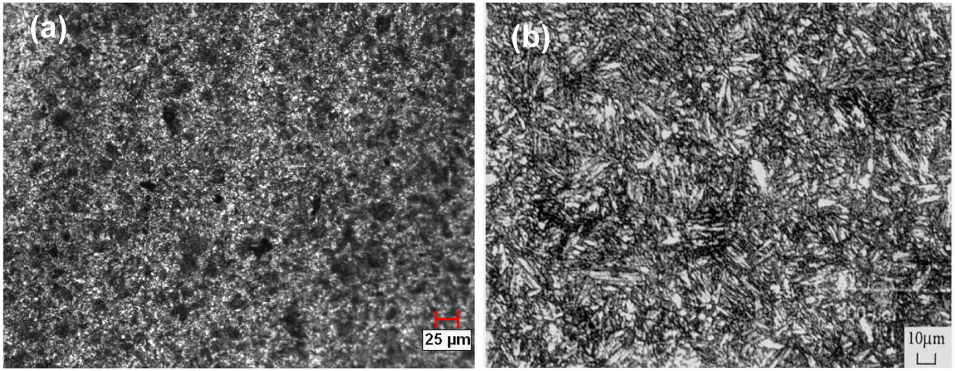
Microstructure of the AISI 4340 steel: (a) nonheat treated and (b) heat treated (as-quenched martensite structure at 850 °C: 30 min). 12
The case hardening steels are unalloyed or low-alloy steels with a typical carbon content of 0.15–0.20 wt%. They are expected to have an initial microstructure, which is a mixture of ferrite and pearlite, which in some applications is cold headed or machined prior to carburization at about 900 °C and subsequently hardening. The surface of the component is then wear resistant, whereas the core remains tough and ductile. The properties required from the core determine the minimum steel hardenability. In components such as gears or diesel injection systems, it is necessary for the core to be strong as well as tough, so the final microstructures must be fine, usually tempered martensite. 14 While iron is the chief element in steel, carbon is the most important alloying element in terms of its strengthening effect on iron. Small amounts of carbon increasing to as high as 0.80–0.90 wt% steadily increase its strength and hardness. Nitrogen is frequently used to provide the similar strengthening; generally, for case hardening (nitriding), relatively high concentrations of sulfur and phosphorus can improve the machinability and excellent forgeability. 16
Several researchers have reported that tempering stabilizes the retained austenite and make it more difficult to transform.17 –19 Cryogenic treatment (CT) after quenching and before tempering results in almost complete conversion of the retained austenite in AISI D2 steel to martensite. 20 These observations are in agreement with the reported results for cryogenic-treated M2 steel18,19 and AISI 52100 steel. 21 It has also been reported that tempering after CT on W18Cr4V and WOMoSCr4v2 steel could increase their impact on toughness by 58% and 43%, respectively. 22 Collins and Dormer 23 studied the effect of soaking time on hardness at different austenitization temperatures in D2 steel. They have found that hardness increases with increased soaking temperature, largely due to increase in martensitic transformation in the steel during long soaking periods. They also observed that the improvement in mechanical properties due to CT is by alloying the molecules to compress and expand in more uniform and homogeneous manner, which in turn reduces the internal stresses as well as wear resistance and improves the life of the specimens.
Cutting tool materials
Considering the characteristics of hardened steels, the applicable cutting tools should have high hardness; high hardness-to-modulus ratio; high thermal conductivity; high abrasive wear resistance and high thermal, physical and chemical stability. 24 The coated carbide, ceramic, CBN and polycrystalline cubic boron nitride (PCBN) tools are widely used for the machining of hardened steels.
The carbide tools are the most common cutting tools used for machining of cast iron and alloy steels. These tools have high degree of toughness but poor hardness compared to advanced materials such as ceramics and CBN. In order to improve the hardness and surface conditions, carbide tools are coated with hard coatings such as titanium carbide (TiC), titanium nitrate (TiN), alumina (Al2O3) and titanium carbonitride (TiCN). While many ceramic materials such as TiC, TiN and Al2O3 possess higher temperature strength and lower fracture toughness than that of conventional tool materials such as high-speed steels and cemented tungsten carbides. The machining of hard and chemically reactive materials at higher speeds is improved by depositing single-layer and multilayer coatings on conventional tool materials to combine the beneficial properties of ceramics and traditional tool materials. The majority of carbide cutting tools in use today employ chemical vapor deposition (CVD) or physical vapor deposition (PVD) hard coatings. The high hardness, wear resistance and chemical stability of these coatings offer proven benefits in terms of tool life and machining performance. 25
Sintering CBN particles mixed with cobalt, TiC, TiN, TiCN or other materials forms PCBN tools. In general, there are two categories of PCBN tools, namely, high-CBN content tools that consist of 90% volume of CBN grains with metallic binders (e.g. cobalt) and low-CBN content tools that consist of 50% volume–70% volume of CBN grains with ceramic binders (e.g. TiC, TiN). PCBN tools have extremely high hardness and high thermal stability and wear resistance. 24 PCBN is the second-hardest material, next to diamond. However, they are also brittle and prone to fracture. Hence, a large negative rake angle with special edge preparation is applied to strengthen the tool edge. 26 A larger nose radius is adopted to improve the surface finish and tool life. 27 An overview of the work materials, cutting tools and tool geometries used in hard turning from various researchers is presented in Table 1.
Overview of different work materials and cutting tools with tool geometries used in hard turning
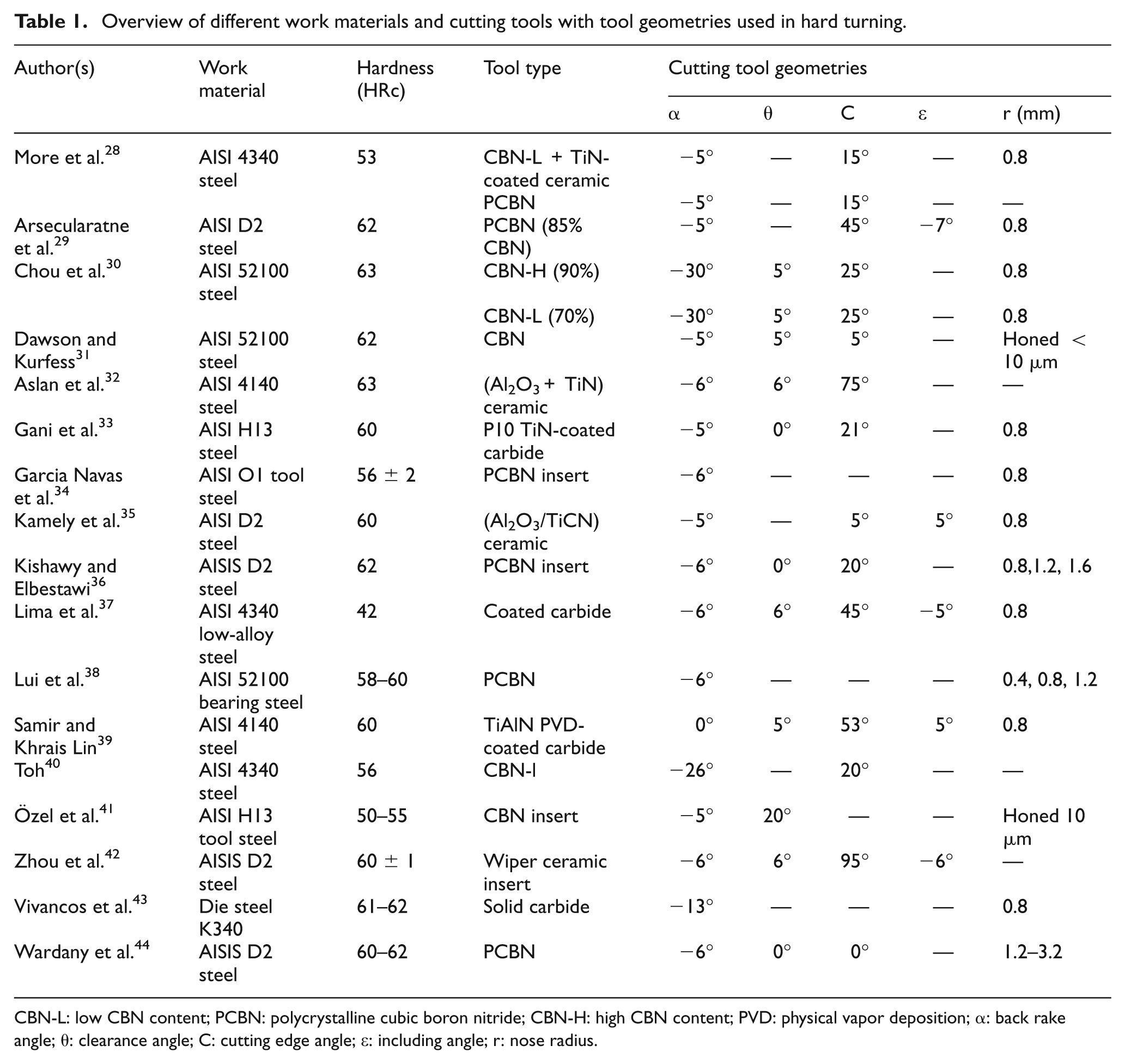
CBN-L: low CBN content; PCBN: polycrystalline cubic boron nitride; CBN-H: high CBN content; PVD: physical vapor deposition; α: back rake angle; θ: clearance angle; C: cutting edge angle; ε: including angle; r: nose radius.
Extrinsic factors
The extrinsic factors such as machine tool rigidity, cutting parameters, tool grade, tool geometry and environmental conditions (wet/dry machining) have significant influence on hard machining process.
Rigidity of machine tools
In hard machining, as the material is harder, specific cutting forces are larger than the conventional machining. The large negative rake angle tool used for hard turning yields large dynamic radial forces that require adequate machine rigidity, spindle power, damping characteristics and accuracy of motion along the axes of the machine. 24 Kopac 45 observed that tool failure occurs due to edge fracture when machining in a poor stiffness setup. Such needs have led to recent machine tool designs that improve stiffness and damping by several methods. New machines have incorporated polymer composite materials in the machine base, reduced number of joints in the machine and developed improved slide ways such as hydrostatic designs. Advances in the control capabilities have improved the accuracy of the machines and reduced productive as well as nonproductive times. The successful hard turning is dependent upon a machine with a high dynamic stiffness, efficient work and tool holding devices, cutting tool grade and tool geometry, appropriate machining parameters and chip management and cooling systems. 46
Effect of cutting tool geometry
Tool geometry has a significant influence on chip formation, heat generation, tool wear, surface quality and integrity during hard turning. The variation in tool geometry (i.e. nose radius of tool, rake angle), variable edge geometry, wiper geometry and curvilinear edge tools and their effect on tool wear and surface integrity of the machined surface are most important to understand the hard machining process.
Cutting edge
Hard turning with CBN cutting tools demands a careful design of tool geometry. CBN cutting tools have lower toughness than other common tool materials, thus chipping is more likely. 47 Therefore, a nose radius and proper edge preparation are essential to increase the strength of cutting edge and achieve constructive surface characteristics on finished metal components. In PCBN cutting tools, several types of edge preparation can be made for hard turning operations, including sharp edge, chamfers, hones and chamfers plus edge hones (Figure 2). Diniz and Oliveira 48 investigated tool life of low- and high-CBN content tools with chamfered and round (honed) edges during turning of hardened steel. It was found that the low-CBN content tool provides better tool life for both types of cutting edges, while edge rounding increases contact area between the tool and workpiece resulting in increased heat dissipation that in turn increases tool life in case of high-CBN content tool.

Types of edge preparation for CBN cutting tools.
The cutting tool edge geometry, which means the chamfer angle, chamfer width and edge hone, has a significant influence on tool life, and to a large extent, it determines the surface finish and surface integrity of the machined part. Due to extreme hardness of the workpiece in hard turning, a negative rake angle with strong edge geometry with a chamfer and hone is employed, in order to withstand the high cutting forces, stress and temperature, which are generated during turning.33,49
Wiper geometry
Recently, high feed rate machining without sacrificing surface roughness becomes an important development with the introduction of wiper geometry inserts. 50 The essence in hard turning with multiradii wiper tools is to give an insert a more flat surface on the secondary cutting edge and wipe the scallops that are typical forms in inserts with a simple nose radius. Hard turning with wiper inserts provides an improved surface finish or increases the feed rates by a factor of 2, hence results in either better surface finish or higher productivity in hard machining applications.51 –54
Grzesik and Wanat 53 presented experimental results for machining AISI 5140 workpiece with a hardness of 60 HRc using both conventional nose radius and wiper geometry mixed ceramic inserts (Figure 3). The results showed that with 0.1 mm/rev for conventional and 0.2 mm/rev for wiper tools, the surfaces obtained have similar three-dimensional (3D) height roughness parameters and comparable values of skew and kurtosis, but for defined cutting parameters, surface produced by wiper tools contain blunt peaks with distinctly smaller slopes resulting better bearing properties. Özel et al. 54 showed that lower average surface roughness values are in the range of 0.18–0.20 µm with wiper tools. In general, low feed rates provided better tool life, and better surface quality products were obtained at the lowest feed rate and highest cutting speed combination.
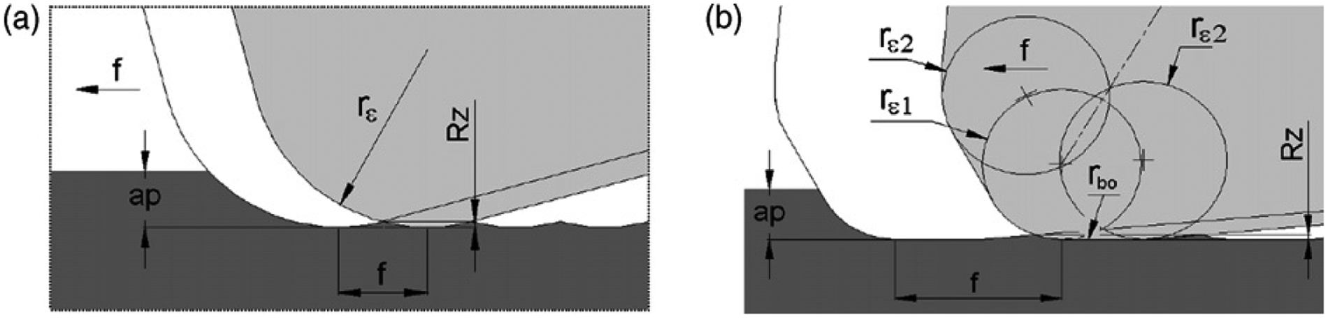
Comparison of inserts with (a) conventional geometry and (b) wiper shape (symbols: f = feed rate; ap = depth of cut; rε = radius of the tool corner; rε1 and rε2 radii of wiper curvature; rbo = radius of smoothing part; Rz = valley-to-peak height). 53
Variable edge microgeometry
Generally, a uniform edge microgeometry along the corner radius of the insert creates a very low edge radius to uncut chip thickness at the minor cutting edge. These causes more plowing than shearing at the minor cutting edge resulting in excessive heat built-up and rapid wear. A variable edge microgeometry along the corner radius of the insert has the potential to reduce this heat built-up at the cutting edge enabling hard turning at higher cutting speeds and feed rates with less tool wear. 55 While uniform edge preparation strengthens tool cutting edge, it makes cutting less efficient especially when the ratio of uncut chip thickness to tool radius decreases. This is especially true when friction factor increases with the decreasing uncut chip thickness-to-edge radius ratio. The work material is trapped near the end of the uncut chip geometry along the corner radius. Inefficient cutting results in increased strains in the workpiece, which in turn increases mechanical and thermal effects, resulting in high temperature. 56
Özel et al. 26 also studied the turning of annealed and hardened AISI 4340 steel using PCBN inserts with four different microgeometries. As illustrated in Figure 4, for variable microgeometry tool edge radius at point A-A is greater than that of at point B-B and C-C (rA > rB > rC). The investigative results indicated that more efficient cutting could be performed due to variable edge microgeometry design, resulting in lower radial forces but slightly higher tangential forces. It was also observed that variable microgeometry tool design reduces the heat generation along the tool cutting edge. Variable microgeometry insert cutting edge induced less plastic strain on the surface, and tool wear decreased with the use of a variable microgeometry insert.
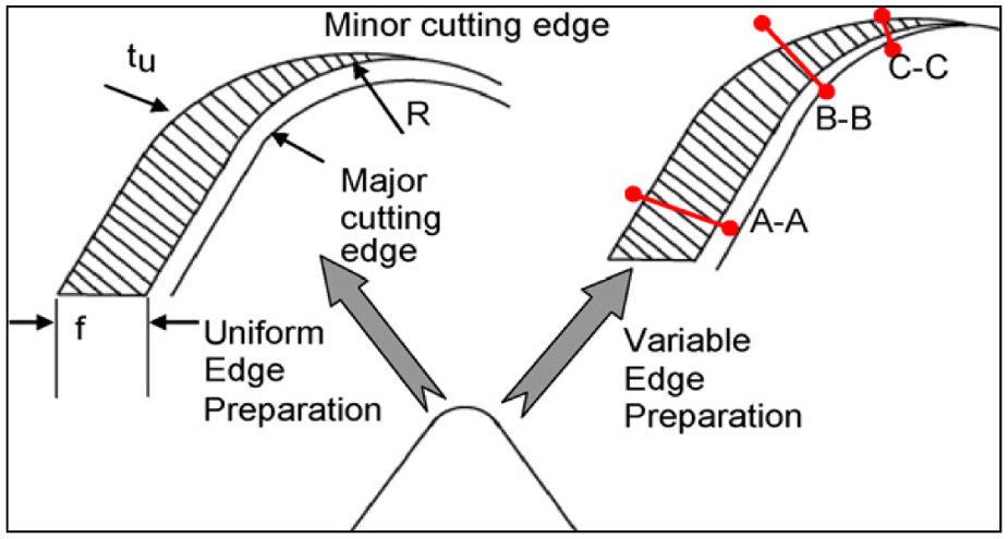
Uniform and variable microgeometry designs. 26
Nose radius of tool
Among various machining parameters, nose radius of tool has a significant contribution to the cutting dynamics and the stability of a machining process. Nose radius is a major factor that affects surface finish of the machined surface. A larger nose radius produces a smoother surface at lower feed rates and a higher cutting speed. Large nose radius of tools has, along the whole cutting period, slightly better surface finish than small nose radius of tools. 57 Chou and Song 27 investigated the effects of nose radius of tool on finish turning of hardened AISI 52100 steel using ceramic inserts with tool nose radii ranging from 0.4 to 2.4 mm. The result showed that large nose radii of tool only give better surface finish. Liu et al. 38 reported that the increased nose radius of tool leads to an increased radial force during hard turning.
Rake angle
In machining of hard work materials, back rake angle must be small, even negative for carbides, ceramics and PCBN tools. Higher the hardness, smaller the back rake angle used. 58 The magnitude of rake angle has significant effect on the performance of cutting tool and surface integrity generated during machining. 59 Jacobson 60 reported that the effective rake angle and nose radius of the tool affect the amount of residual stress generated. Higher negative rake angle and smaller nose radius created a more compressive residual stress profile.
Many researchers observed that the tool geometry has high influence on hard machining process. A chamfer/honed cutting edge strengthens the tool, while wiper geometry gives better tool life and surface finish. A negative rake angle with variable microgeometry tool design reduces the heat generation. A large nose radius of tool produces better surface finish, whereas an increased nose radius of tool leads to an increased radial force during hard turning process.
Cutting forces in hard machining
The forces acting on a tool is an important aspect of hard machining. The knowledge of cutting forces is essential to estimate the power requirements and make sure that the machine tool elements, tool geometry, tool holders and fixtures are adequately rigid and free from the vibrations. An overall overview of the machining parameters on cutting forces, chip formation, tool wear and surface roughness is presented in Table 2.
An overview of the different cutting parameters on cutting forces, tool wear, chip formation and surface roughness
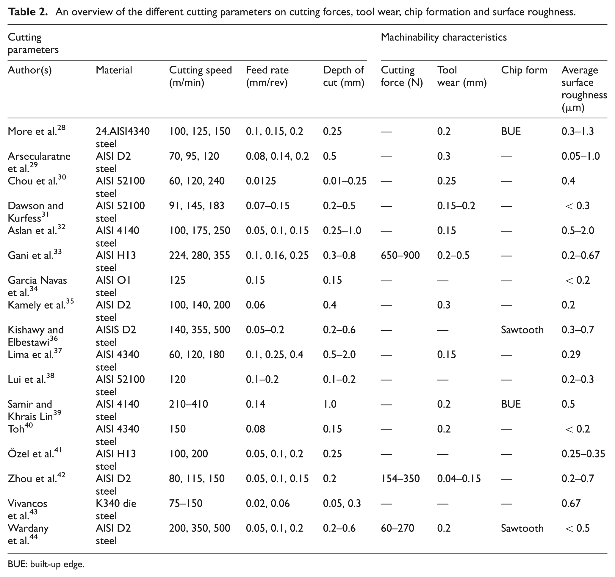
BUE: built-up edge.
Several researchers have reported that the cutting forces are influenced by a number of factors such as cutting conditions, cutting time, workpiece hardness and tool geometry.37,41,61 Chen 61 reported that radial force was the largest among cutting forces during machining of medium-hardened steel (45–55 HRc) using CBN tool. Lima et al. 37 found that three components of machining forces, namely, radial force, axial force and tangential force, decrease with increased cutting speed. The reduction in the forces was probably due to the increase in temperature in the shear plane area, resulted in reduction in the shear strength of the material. Similar results were reported elsewhere.62 –64
Gaitonde et al. 65 observed that the machining force and power linearly increase with increased depth of cut and machining time during hardened AISI D2 cold work tool steel with wiper ceramic inserts. However, hard machining using conventional ceramic inserts, the machining force and power were found to increase with increased depth of cut up to 0.45 mm and then suddenly decrease with further increase in the depth of cut. The probable reason might be, in the conventional ceramic insert, tool wear causes the geometry of the cutting edge to become less negative, in contrast to wiper tools for which tool wear is substantially lower. 66 Lalwani et al. 67 inferred that the cutting speed does not significantly influence forces for the cutting speed up to 144 m/min during finish hard turning of MDN 250 steel. However, the depth of cut affects the axial force, while both the feed rate and the depth of cut affect radial and tangential forces. Furthermore, it was observed that the cutting forces were most influenced by the depth of cut compared to the feed rate or cutting speed.
Liu et al 38 analyzed the cutting forces depending on the nose radius of the tools in machining of bearing steel using CBN tools. They found that the radial force is larger than the tangential force and the radial force increases significantly when the nose radius of the tool increases. It was also shown that the cutting forces slightly increase with the increased nose radius of the tool. Tönshoff et al. 68 noted that the radial force component appears to be larger during hard turning of ASTM 5115 steel. A relatively significant rise of radial force was observed when compared with the other two force components due to a progressive increase in tool flank wear.
Qian and Hossan 69 presented comparative analysis of numerical simulations and experimental results. Tangential and axial forces were determined in the numerical simulation technique, among process parameters, cutter geometry and workpiece hardness and feed rate. With the same cutting conditions, turning AISI 4340 steel gives the highest tangential force, turning AISI 52100 steel has the highest axial force, while turning AISI D2 steel provides the lowest tangential force and axial force. Tangential force and axial force increase with the increased feed rate, tool edge radius, negative rake angle and workpiece hardness.
Tool geometry is also an important factor affecting machining forces, especially the axial and radial force components. 70 Low depth of cut leads to low true side cutting edge angle values, thus resulting in high radial force. On the other hand, large nose radius and cutting edge angle values improve the surface finish of the machined part and decrease the tool vibration. Yallese et al. 71 reported that the radial force is dominating in hard machining of hardened bearing steel using CBN tool. Such finding is in contradiction with the concept of conventional turning in which radial force is about 30%–50% from the tangential force. Consequently, the radial force cannot be neglected in characterizing static and dynamic behaviors of such machining system.
The force conditions in hard turning are different from that of conventional turning such as the radial force is dominant compared to the tangential force and axial force. The cutting forces increase with an increase in feed rate, depth of cut and nose radius. During hard turning, the cutting forces are higher at low cutting speeds and decrease when cutting speed is increased. This behavior may be due to the fact that at low cutting speeds, high cutting forces are encountered due to low cutting temperature and built-up edge (BUE) formation. 72 The high cutting speeds result in high cutting temperature thus and reduce the forces due to thermal softening of the workpiece material.
Chip formation in hardened steel machining
In conventional metal removal processes, chips are formed as a result of workpiece shearing. The mechanics of chip formation in hard turning are quite different from those in softer steels, where continuous chips have typically been observed. In hard turning, serrated/periodic sawtooth chips are formed. Such chip is the result of some interrelated mechanisms such as localized shear, adiabatic shear and catastrophic shear in the form of extensive cracks.73,74 The morphology of chip formation depends on mechanical, thermal and thermomechanical properties of the material. Cutting conditions, divergence of shearing in the shear zone, possible interaction between primary and secondary shearing zones and dynamic response of the machine tool structure and its interaction with the cutting process also influence the chip formation. 75
Poulachon and Moisan 75 conducted quick stop tests to investigate the chip formation mechanism of hardened AISI 52100 steel. They identified four stages in the formation of a sawtooth chip as shown in Figure 5. In the first stage, negative rake angle induces the distribution of compressive stresses around the tool edge radius. At the free surface of the work material in front of the tool chamfer, the jointed effect of low compression stresses and high shear stresses initiate crack. The crack is followed by a slip plane, which runs toward the cutting edge. The second stage occurs between the crack and edge chamfer where the chip starts to eject practically without any deformation. In this stage, martensite produced by friction can occur in the form of white layers near the chip segment, and high values of radial force are shown. The third stage is that the gap crack initiation line and tool chamfer become so narrow that the ejection speed and the plastic deformation of the chip are very high. By this time, the chip thickness is shrunken and chip cooling is very fast. Fourth, and the last, stage shows that the formation of the chip segment is completed. The gap crack initiation line and tool chamfer are closed, and new crack starts to open at the same time.
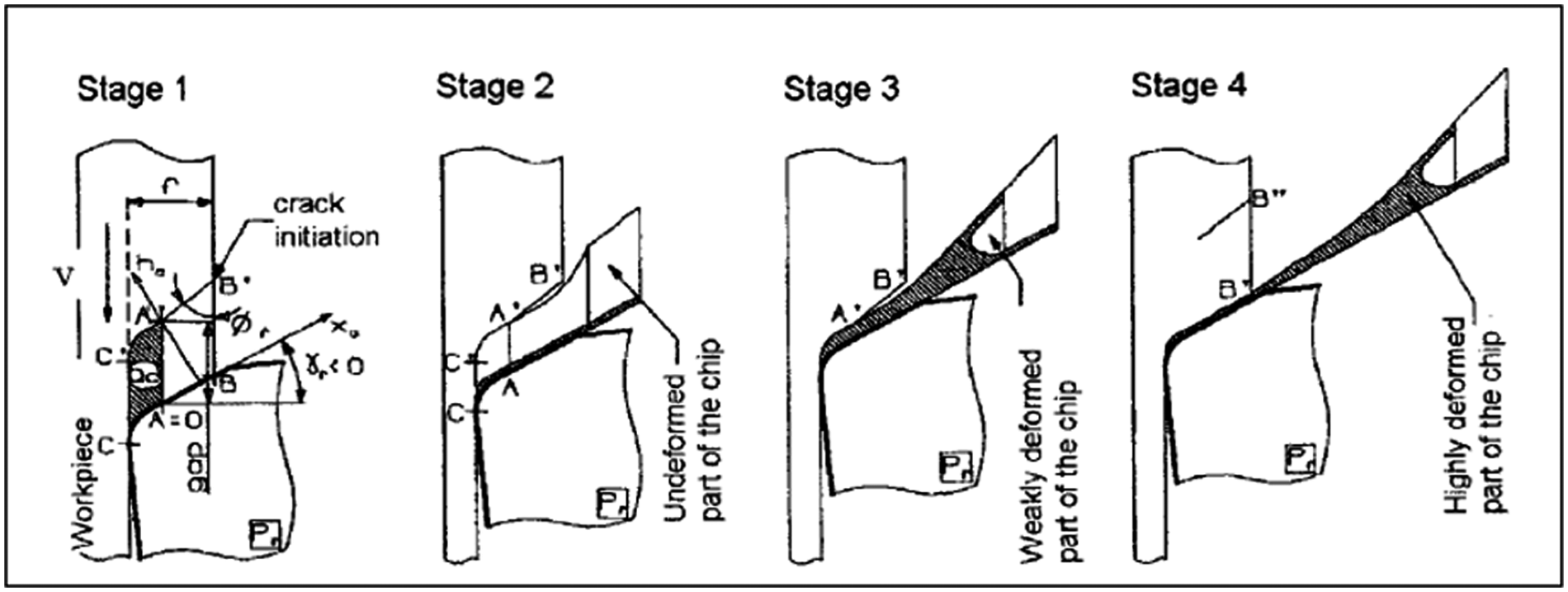
Four stages of chip formation in machining of hardened steel. 77
Ng et al. 76 observed the sawtooth chip formation at all cutting conditions. However, the grains of the microstructure along the tool/chip interface are not as severely deformed as chip section under low cutting speeds. At higher cutting speeds, a white layer was observed under heavy strains and high temperatures followed by rapid cooling. Lee and Mathew 77 showed that the catastrophic shear bands (white bands) appear in secondary deformation zone, when machining the AISI 4140 steel at high cutting speeds and the chip formation can change from a continuous chip to a sawtooth chip as the cutting speed increases. John and Gerald 78 experimentally investigated the chip formation in machining of heat-treated AISI 4340 low-alloy steel. The transition from continuous to sawtooth chip formation was observed when increasing the cutting speed, the feed rate, the hardness of work material and negative tool rake angle.
Tool wear and tool life
Tool wear and tool life are very important aspects of hard turning as tool wear leads to tensile residual stresses and white layer formation on the machined surface. Tool life should be carefully observed in the hard turning since it is finishing operation requiring better surface finish comparable to grinding. The tool life criteria used in hard turning are usually based on predetermined surface alteration. 39
In hard machining, high hardness of workpieces, large cutting forces and high temperatures at tool–workpiece interface impose extreme requirements for tool rigidity and tool wear resistance. Generally, adhesion, abrasion and diffusion type of tool wear mechanisms are observed in hard machining. However, tool wear rate depends on several factors such as tool material, tool geometry and cutting parameters.28,79 Poulachon et al. 80 identified the presence of various hard carbides in steel as the major influencing factor on tool wear, which caused wear grooves on tool flank by abrasion. They observed the differences in wear rates, which were attributed mainly due to different hardness values of the various carbides in the steels. Luo et al. 81 reported that the main tool wear mechanism is due to abrasion of the binder by hard carbide particles in the steel work material.
Several investigations have been carried out to study the performance of coated carbide, ceramic and CBN tools during machining of hard materials. When turning of quenched tempered AISI 1045 and AISI 5140 steels with TiN-coated carbide inserts at low speeds, adhesion and microchipping are the basic wear mechanisms, while at high speeds, diffusion and thermal fatigue cracking become severe. 62 The increase in cutting speed results an increased temperature at the contact tool. Thus, at elevated temperatures, chemical wear becomes dominant wear mechanism. It accelerates deterioration of cutting edge, resulting in premature tool failure, namely, edge breakage of the cutting tool. Cho and Komvopoulos 82 investigated the performance of two-layer (TiC/Al2O3) and three-layer (TiC/Al2O3/TiN)–coated carbide tools using hard turning. They observed that three-layer–coated tools have high wear resistance compared to two-layer–coated tools.
Suresh et al. 83 investigated the machinability of hardened AISI 4340 steel using CVD multilayer-coated cemented carbide tools. They reported that the abrasion was dominant wear mechanisms, although chipping on the flank and rake faces and catastrophic failure were also observed at higher cutting parameters. Ciftci 84 reported that TiN coating has a lower coefficient of friction than Al2O3 coating during dry turning of austenitic stainless steels using CVD multilayer-coated cemented carbide tools. Bouzakis et al. 85 stated that the film failure development after the coating fracture initiation was less intense in the case of the multilayer coating. It was attributed with deceleration of potential crack propagation within the layered TiN/TiAlN structure. They reported that applying the multilayer coatings, tool life could be improved.
The hardness of coating is the most important requirement to resist flank wear due to its high wear resistance against abrasion. 86 Knutsson et al. 87 illustrated the improved wear resistance of TiAlN/TiN multilayer coating. It is attributed to the multilayer hardening effects and improved thermal stability. Better tool life could be achieved using PCBN tools, but cost of PCBN tool is as twice as that of the coated carbide tool. 88 Machining medium-hardened steels with TiCN/Al2O3/TiN inserts tends to be more productive. The relatively good performance of coated carbide tools on machining hardened steel relied on coating combination of layers, which seems to be the adequate one for such applications.
Some researchers have used ceramic and coated ceramic tools for turning of different types of hardened steels. They reported that during machining hardened steels using titanium-based cermet tool, adhesion and abrasion were the dominant wear mechanisms, but while machining bearing steel with the same tool, microchipping, cracking and plastic deformation were the main wear phenomena occurred.29,32,89 Aslan et al. 32 reported that during hard turning of AISI 4140 steel with Al2O3 mixed ceramic tool, tool wear decreases almost linearly with cutting speed due to high degree of brittleness of ceramic tools indicated by chipping observed on the flank face of these tools, rather than smooth abrasive wear.
Grzesik and Zalisz 90 demonstrated that wear mechanism in ceramic tools involves complex phenomena such as abrasion, fracture, plastic flow, material transfer and tribochemical effects, depending on mechanical and thermal conditions. Kumar et al. 91 compared the performance of SiC whisker–reinforced and Ti(C, N) mixed alumina ceramic cutting tools. They concluded that flank wear could be attributed to rubbing of flank land with the machined surface and high temperatures causing abrasive and/or adhesive wear. The rake face suffers from tribochemical wear (diffusion, adhesion and abrasion), and its rate depends on the solubility of Ti(C, N) in steel at high temperatures.
While machining AISI 52100 hardened steel (62 HRc) using ceramic-coated and uncoated CBN cutting tools, the smooth crater surfaces formation was observed on the low-CBN content tools. Both the TiN- and TiAlN-coated tools showed significant chipping of the coated layer. Once the coating had been worn away, smooth crater surfaces were formed in the CBN substrate, similar to wear of the uncoated tools. The uncoated wiper geometry tools behaved very similar to the uncoated tools from the same supplier, except that tool life was shorter at each condition. 31 Zhou et al. 42 showed that with increase in chamfer angle, all the three force components increase, while tool life initially increases and reaches to a maximum value at chamfer angle of 15°. With further increase in chamfer angle, tool life suddenly decreases, indicating an optimum angle of 15°.
The adhesion, abrasion and plastic deformation are the main factors, which influence tool wear in coated carbides, ceramics and CBN tools during hard machining. Tool wear has significant effect on surface roughness profile. Employing lower values of cutting parameters with proper tool geometries could minimize tool wear. Ceramics and CBN inserts exhibit better tool life at the highest cutting conditions due to their high hardness and melting point for hard machining steels.
Intrinsic factors
The intrinsic factors are the material factors affected by external cutting conditions on the machined surface and subsurface of the workpiece. It includes surface roughness, waviness, material side flow, plastic deformation, phase transformations, surface hardness, redeposited layers, macro/microcracks, cavities and residual stress distribution.
Surface integrity
The quality of machined surface becomes more critical in view of very high demand for performance, safety, lifetime, life cycle costs and reliability. The engineered components used in aerospace, automotive, machine tools and other industries are subjected to high stress and surrounding temperature. Hence, surface topography requirement of machined components becomes more important, which will cause a sudden fatigue failure; therefore, further research and development on machined surface of hardened steel components are required. The study on surface integrity depends not only on surface roughness but also on surface hardness, subsurface deformation, macro/microcracks, plastic flow of material, tensile residual stress and reduced fatigue life.6,92 Surface integrity is the unimpaired surface condition developed in machining using controlled manufacturing processes. The surface integrity has two important categories, namely, surface texture and surface metallurgy.
Surface texture
Surface texture is the inherent or enhanced condition of a surface produced in machining or other surface generating operation. Surface texture is generally quantified as surface roughness values. The surface roughness of machined surface has an important effect on the functional properties and performance of machine parts. It affects the wear resistance, fatigue strength and corrosion resistance of the part. The surface roughness values can be determined from cutting parameters and tool geometry. Moreover, the BUE and tool wear can affect the qualities of the machined surface.40,93,94
Lima et al. 37 showed that the surface finish of the machined part improves with increased cutting speed, while it deteriorates with increased feed rate during hard machining. The depth of cut presented little effect on the surface roughness values. Chou et al. 30 investigated the effects of cutting conditions, material properties and wear of CBN tools on surface quality. For finish turning, the use of low-CBN content produces better surface finish compared to higher CBN content, with better tool wear resistance. Subsequently, Chou and Song 27 reported that the large nose radius of tool gives a finer surface finish in turning AISI 52100 steel. Davim and Figueira 95 evaluated the machinability characteristics during hard turning of AISI D2 tool steel with ceramic tools using statistical techniques. The results of the tests showed that with the appropriate choice of cutting parameters, it is possible to obtain a surface roughness (Ra < 0.8 µm) that allows cylindrical grinding operations to be eliminated.
From the above, it can be concluded that the surface finish is affected by number of factors such as hardness of work materials, cutting parameters and tool geometry in hard turning process. The feed rate and nose radius of tool are believed to be the most dominant control factors. 96 In finish hard turning, feed rate applied is generally very small and is equal to the nose radius of tool or even smaller. The plowing effect and material side flow effect are pronounced at such cutting conditions, which pose difficulty in predicting surface finish. 6
Material side flow is a unique phenomenon of the plastic flow of brittle material. This is attributed to squeezing effect of the workpiece material between the tool flank and the machined surface when the uncut chip thickness is less than a minimum value. 6 During chip formation, a minimum undeformed chip thickness is required below which a rubbing effect takes place. This minimum chip thickness depends on many factors such as lower feed rate, higher cutting speed, workpiece hardness, tool wear and tool geometry.96 –98 Additionally, it can also result from flowing of highly plasticized material through the worn trailing edge to the side of the tool. Kishawy and Elbestawi 98 reported the effect of process parameters on material side flow during hard turning using PCBN tool. The side flow of workpiece material is facilitated by high temperature and normal stress in the cutting zone, where the workpiece material at chip/tool interface and work/tool interface behaves as a viscous fluid as shown in Figure 6. Kishawy and Elbestawi 36 investigated the surface integrity of AISI D2 steel (62 HRc) machined using PCBN tools under high-speed conditions. The results showed that the surface roughness increased with an increase in the tool wear at cutting speeds above 350 m/min and was attributed to material side flow.
Effect of edge preparation on material side flow (V = 250 m/min, f = 0.05 mm/rev, d = 0.125 mm, r = 3.2 mm). 100
Surface metallurgy
Surface metallurgy is the metallurgical alterations produced at or near the machined surface. Several causes can be attributed to poor surface integrity, including subsurface plastic deformation, phase transformations, intergranular attack, thermal softening or hardening, redeposited layers, micro/macrocracks, recrystallization and residual stress distribution. Typical surface integrity problem includes machining burns, untempered martensite, cracks on the surface, lower fatigue strength of parts, distortion and residual stresses and their effect on distortion, fatigue strength and stress corrosion.34,99
White layer is believed to be detrimental to the part performance and can affect its tribological performance, corrosion resistance and fatigue life. 100 Hence, it is vital to understand the white layer formation and to minimize its thickness during the hard machining. It has been noted that under the circumstance of excessive flank wear or aggressive cutting conditions, workpiece surfaces produced by hard turning can exhibit surface alterations that are referred to as white layers.43,44,101 –103 The characteristics of such layers appear to vary considerably in structure and thickness (few micrometers) depending on the operating machining conditions suggesting different possible mechanisms. As reported by Griffiths, 103 white layer formation resulted from the following:
mechanical grain refinement arising from severe plastic deformation;
thermally induced phase transformation due to high cutting temperature resulting from rapid heating and quenching;
surface reaction with the environment such as carburizing, nitriding and oxide plowing.
White layers can be termed as an outcome of high friction energy and heat generated during cutting process due to tool wear or by very high cutting speed.104 –106 Martensite in steel transformed into austenite to structure the white layer due to high temperature conditions. Chou and Evans 104 reported the formation of white layer and flank wear for various cutting speeds in hard turning. They found that the white layer depth progressively increases with tool flank wear. Ramesh et al. 101 investigated the white layer during hard turning of AISI 52100 steel with CBN insert. From the results of transmission electron microscope (TEM), they suggested that white layers produced at low-to-moderate cutting speeds were largely due to grain refinement induced by severe plastic deformation. Moreover, the white layer formation at high cutting speeds was basically due to thermally driven phase transformation. The white layers at all speeds were found to be composed of very fine (nanoscale) grains compared to bulk material. Umbrello et al. 106 developed the models to study the white and dark layer formation in hard machining of AISI 52100 bearing steel. The model was validated with experimental results, and good correlation was found. It was found that the white layer thickness increases with increased cutting speed, while the dark layer thickness decreases.
Kishawy and Elbestawi 36 investigated the surface integrity of AISI D2 steel of 62 HRc machined using PCBN tools under high-speed conditions. A heat-affected zone is shown as a continuous white layer of untempered martensite with a thickness of approximately 0.1 mm. The heat-affected zone is hardly noticeable at the high cutting speed when using a sharp tool as shown in Figure 7. This indicates that machining under these conditions can eliminate the existence of the unfavorable white layer. In addition, defects such as microcracks and cavities were observed on the machined surface. The density of such microcracks was found to depend on the cutting speed and feed rate employed.
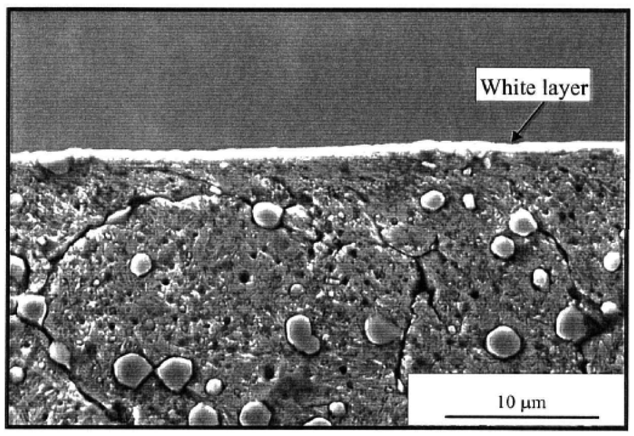
SEM view of the machined subsurface structure of D2 tool steel. 36
Ramesh et al. 107 stated that high plastic deformation occurred on the surface of hardened AISI 4340 steel after machining. Nanoindentation hardness test of the work material revealed a general trend of increased hardness of white layers with an increase in the cutting speed. Ekinovic et al. 108 presented the range of critical speeds and feed rates for minimizing the adverse effects of white layer formation on surface integrity.
Bosheh and Mativenga 109 illustrated that the hardness of machined surface was increased compared to bulk material. Compositional gradients were noted for the white layer in terms of depletion of the elements iron and chromium coupled with an enrichment of carbon and oxygen content. Although tool wear increases with the cutting speed, the white layer depth and hardness actually reduced. Hence, there may not be a direct relationship between white layer formation and wear, but the correlation may be linked to wear mode.
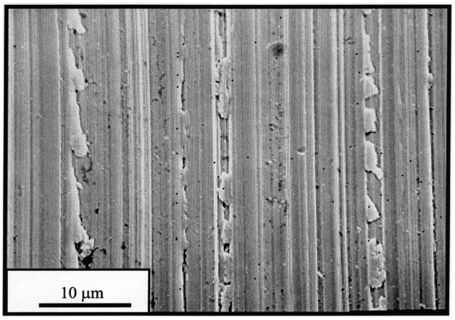
Poulachon et al.’s 80 results confirm the effects of grain size and the microstructure on the formation of white layer for a range of work materials including AISI D2 cold-worked steel, AISI H11 hot-worked steel and AISI 52100 bearing steel. Thiele and Melkote 110 investigated the effect of tool edge geometry on workpiece subsurface deformation in hard turning of AISI 52100 steel. Their results showed that large edge hone tools produce plastic flow of workpiece material in the circumferential direction as shown in Figure 8.
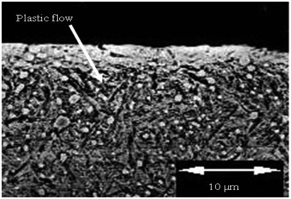
SEM view of workpiece plastic flow: 121.9 µm hone, 0.15 mm/rev feed rate and 57 HRc workpiece. 112
Kamely et al. 35 investigated the effect of single-pass and multiple-pass cutting on the surface integrity when hard turning of AISI D2 cold work tool steel using ceramic tool. The flank wear of the tools has a significant effect on the quality of the machined surface. Figure 9 shows the comparison of surface microstructure between single-pass and multiple-pass cutting with worn tool. Intragranular cracks were observed with single-pass turning, while transgranular cracks occurred with multiple-pass turning. In both passes, the white layer was observed, but in single pass, there was no subsurface deformed grain orientation, whereas in multiple passes, there was a distinct orientation.
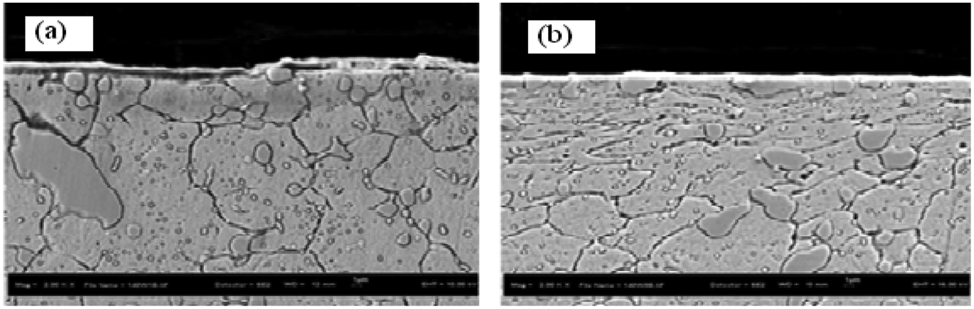
SEM view of machined surface: (a) single pass with worn tool and (b) multiple passes with worn tool on D2 tool steel. 35
Residual stress
Residual stress is one of the most relevant practical parameters used for evaluating the quality of the machined surface, particularly when critical structural components are machined, with the objective to reach the high reliability levels. It is the case for the components made from hardened alloy steels, which are largely used in automobile, aerospace and machine tool industries. Such hardened alloy steels are considered difficult to machine due to their inherent mechanical and thermal properties posing difficulty for machining. As a consequence, high cutting forces are produced along with high localized temperatures around the cutting edge and on the machined surface, thus producing high tensile residual stress levels.
The residual stress profile attributes, including both magnitude and direction along the depth below workpiece surface, are known to significantly affect component fatigue life. Generally, residual stress profiles are compressive at machined surface or subsurface with fresh tool and change to tensile at certain flank wear. There are five main factors that could drastically affect the residual stress distribution in finish hard machining:24,111
insert grade;
tool geometry, including nose radius and edge preparation (chamfer angle and length, hone radius);
cutting parameters such as cutting speed, feed rate and depth of cut;
tools wear progression;
chemical composition and hardness of workpiece material.
Residual stresses in high-performance alloys and steels are of considerable industrial importance because they can influence failure by fatigue, creep or cracking. 112 Several researchers reported the residual stress distributions in hard machining, which are listed in Table 3. The effect of cutting conditions and tool wear on the microhardness variation and residual stress distribution beneath the surface produced during high-speed hard machining of D2 steel were investigated. When cutting temperature exceeds a specific value, mechanical load exerted by feed rate and depth of cut has a pronounced effect on residual stress. 1
Summary of cutting conditions, cutting edge geometries used and the maximum compressive residual stress on hoop and depth direction 116
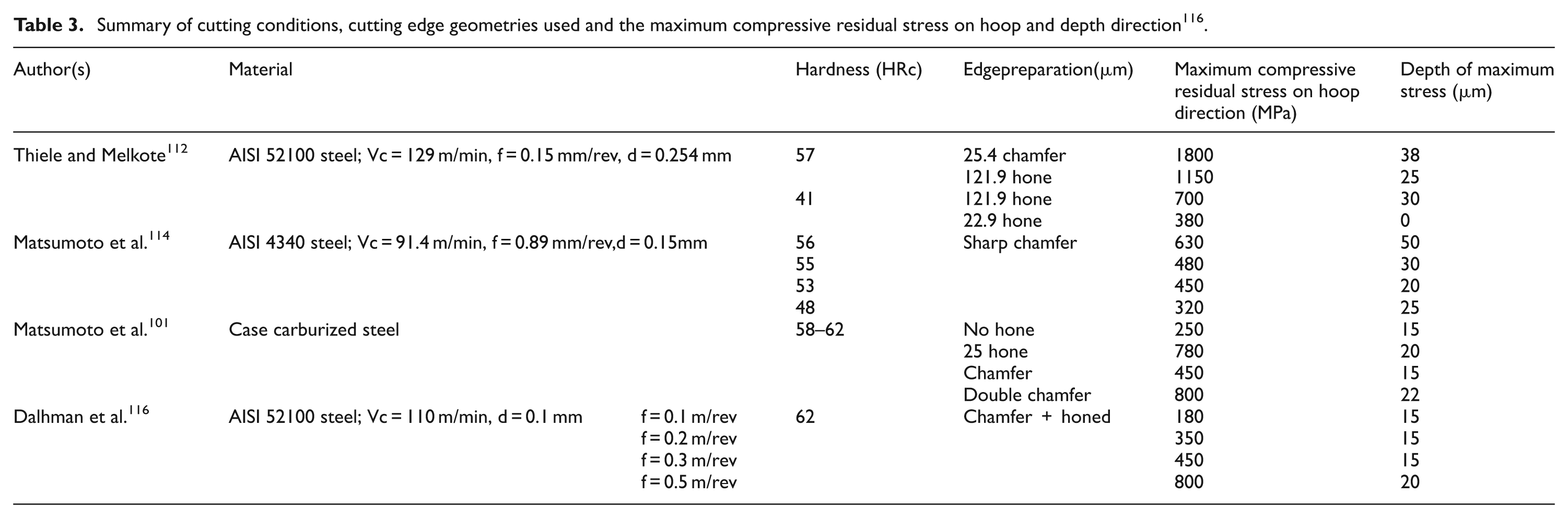
Hua et al. 113 studied the effects of cutting edge geometry, workpiece hardness and cutting parameters on the residual stress in the subsurface using flow stress model. The results revealed that it is vital to keep the feed rate low in order to obtain higher compressive residual stress at low edge temperature with low cutting forces. Agha and Liu 115 demonstrated that the residual stress distributions in both the circumferential and axial directions were compressive. The authors also observed that the wear of the cutting edge (worn tool) resulted in tensile surface stresses in axial direction and significantly lower penetration of residual stress in the circumferential direction.
Thiele and Melkote 110 investigated the effects of tool edge preparation and material hardness on surface residual stress during finish hard turning with PCBN inserts. The results indicated that tools with large edge hone radius and chamfer tool produce more compressive residual stresses than small edge hone tools. Dahlman et al. 116 reported that increased feed rate and use of a negative rake angle generate higher compressive stresses. Jacobson 60 found that effective rake angle and nose radius of tool both affect the amount of residual stress generated.
Matsumoto et al. 114 illustrated similar observations when examining the effect of workpiece hardness on residual stress produced in facing of hardened AISI 4340 steel. In the absence of phase transformations, residual stresses become more compressive as workpiece hardness increased. Matsumoto et al. 99 analyzed the effect of tool edge geometry on residual stress magnitude and depth when investigating PCBN hard turning of case carburized steel. The study illustrates that marginal effect of depth of cut and feed rate on subsurface residual stress, while the effect of edge honing and double chamfer have been shown to result in greater subsurface penetration and compressive stresses.
The unfavorable tensile residual stresses and white layer formation occur at higher cutting speed and feed rates with worn cutting tool. Most of the researchers agree that white layer formation does not have any significant effect on fatigue strength. However, the tensile residual stress on machined surface reduces the fatigue strength of the component. Smaller nose radius of the tool, lower cutting speed and feed rates can produce favorable surface integrity and can help in improving the fatigue life of the component.
Numerical modeling of hard machining process
In recent past, more attention has been paid on modeling for the prediction of machining performances such as cutting forces/power/torque, chip formation/chip breakability, tool wear/tool life, surface finish and part accuracy. A significant progress has been achieved in developing suitable cutting conditions for machining with better performance and selection of appropriate tooling to avoid chattering and vibrations. Predictive model for residual stresses is one of the emerging research topics owing to its correlation with the fatigue life of machined components.116 –121
The computational methods such as numerical modeling using finite element methods (FEMs) have been employed in recent literatures. It gives the most needed boost to simulation and predicting capabilities, despite the questions surrounding the validity of various assumptions made and material constitutive relationships being incorporated in such models. Guo and Liu 118 adopted the Oxley’s cutting theory approach to model hardened AISI 52100 steel for the simulation of hard turning. The cutting forces and cutting temperature were found to be in good agreement with experimental results. Shi and Liu 119 were able to further predict the segmented chip morphology and white layer during machining hardened AISI 52100 steel, based on the same material model.
Özel 120 investigated the effects of tool–chip interfacial friction models on the FE simulations. They concluded that the friction modeling at the tool–chip interface has a significant influence on the FE simulations of machining. Particularly, variable friction models that are developed from the experimentally measured normal and frictional stresses at the tool face resulted in the most favorable predictions. Hua et al. 113 studied the effects of cutting conditions, tool edge configuration and the work material hardness in hard turning of bearing steels, and using commercial FEM software, they predicted the effects of these variables on the axial and circumferential residual stresses.
Discussion
Production is facing the need for higher productivity, flexibility and quality due to the progress of customization and global competitive markets. Over the last decade, new manufacturing strategies like high-speed and high-performance cutting, hard and dry machining, process integration, complete machining and advanced tool material influenced machine tool developments or have been made possible by it. In consequence, productive as well as nonproductive times could be drastically reduced. From both technical and economical viewpoints, hard turning can compete successfully with the grinding process. For instance, hard machining is three to four times faster than grinding, requires few operation and utilizes five times less energy.
Machining of hardened steels depends on several factors, such as tooling used, machining conditions, machinability parameters and material properties. These are diagrammatically illustrated in Figure 10. With the advantages of advanced manufacturing and measurement methods and innovative materials processing techniques, all raising the reliability and quality requirements in manufactured products, the need for predictive modeling and optimization techniques have emerged in recent times.64,121,122
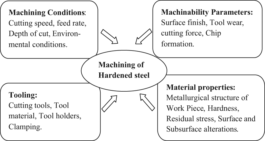
Influence of different parameters on machining of hardened steel.
Computational methods and analytical and experimental techniques are all emerging in large scale for making simulations, predictions and optimization easier, faster and more accurate, while the fundamental understanding of the science of product sustainability is still somewhat lacking. Manufacturers of products for industrial and domestic use, coming from all major segments of the manufacturing industries such as the aerospace, automotive and biomedical, have set high standards and expectations for the use of predictive performance models for their manufactured products, particularly dealing with cyclic loading, impact conditions, corrosion and resistance to environmental and chemical degradation and mechanical wear and tear.
Based on the current review on machinability of hardened steels, it is observed that many researchers have performed experimental investigations on numerous aspects related to hard turning and presented their own recommendations to achieve successful performance of the process. The hard turning is basically a high-speed, low-feed and low depth of cut finishing process. As reported in the literatures, in general, the cutting speeds vary from 100 to 400 m/min, the feed rates operate in the range of 0.05–0.2 mm/rev, while depth of cut is not more than 0.2 mm. It is revealed in the entire literature review that the various factors such as cutting parameters, machine tool characteristics, type of cutting tool material, cutting edge geometry and shapes of inserts largely affect the various machinability characteristics such as machining forces, surface roughness, tool wear and tool life, chip formation, machining power, specific cutting force, surface integrity, residual stresses and white layer formation. The influence of various process parameters on various machinability aspects related to hard turning process has been analyzed through experiments as well as various modeling techniques such as response surface methodology (RSM), artificial neural network (ANN) and FEM.
After reviewing the works on machinability aspects of hard turning, the following observations were made and certain areas have been pointed out, which need to be addressed for further research in hard turning.
Majority of the researchers found that the force conditions in hard turning are different from that of conventional turning. The radial force is found to be more influential than the tangential force in hard turning for all the cutting tool geometries except variable edge hone radius tool. This behavior may be probably due to low feed rate and depth of cut in hard turning process. But no analysis on machining forces during hard turning, in particular, the radial force, has been carried out in any of the literatures. Hence, further investigation is still required on force analysis in hard turning with different cutting parameters, tool materials and shape of inserts through experiments as well as modeling.
In order to eliminate the sharp edge and reduce the edge-related problems (edge chipping, cracks, breakage, etc.), tool geometry is normally modified. Honed edges are commonly employed on diamond, polycrystalline diamond and cemented carbide tools. No work related to the states of the cutting edge (size of edge preparation and edge geometry) and their influence on the machinability aspects in hard turning could be found in the currently available literatures.
Most of the hard turning operations are performed without coolant. Only few researchers have addressed the issues related to hard turning with coolant. The absence of coolant reduces tool life and increases surface roughness of work. On the other hand, it was reported in the literatures that the presence of coolant reduces the white layer thickness during hard turning process. Hence, further research about the use of coolants in the hard turning process is still required.
Even though hard turning is an inspiring process due to its ability to replace grinding as finishing process, there are few limitations of the process as far as white layer and residual tensile stresses are concerned. The residual tensile stresses exist at the surface, while the white layer leads to considerable variations in product part service performance. Only few works have been reported on this area for investigating the behavior of white layer formation and residual tensile stresses during hard turning. The researchers have to contribute in this area to address these issues through modeling and optimization techniques by taking into account various affecting process parameters.
Conclusions
This article has provided a review of the literature and collectively discussed the various researches related to the study of machinability of hard materials. The major challenge in hard machining is selecting cutting tool that facilitates better tool life and high-precision machining. The hard machining requires negative rake angle and lower feed rate and depth of cut. The negative rake angle would offer predominately compressive stress state and stronger edge during hard machining. Additionally, lower feed rate and depth of cut can reduce the cutting resistance. The feed rate is the highest influencing factor on surface finish. The surface finish is improved with increased nose radius of tool. It is also noted that increasing the cutting speed can help to obtain the better surface finish. The depth of cut seems to exert least influence upon the surface roughness values. Tool wear affects the surface roughness, phase transformation, microhardness variation and residual stress induced in the surface and subsurface. A new cutting tool induces compressive residual stresses below the workpiece surface, whereas worn tool causes tensile residual stresses and the appearance of white layer with very fine microstructure.
The quantitative evaluation of the machining process for enhancement of product life depends upon several factors, which include the influence of the parameters on surface integrity, white layer formation and microstructural evolution of work material. The cutting conditions, tool material properties, tool geometry and environmental conditions influence the surface integrity. The microstructural evolution of the work material includes metallurgical structure, workpiece hardness, composition of the material cracks on the machined surface and residual stresses imposed by machining. The implementation of optimal machining condition in machining process and predictive models help to improve the tool life, surface integrity and reduce the machining time of the components.
Footnotes
Funding
This research received no specific grant from any funding agency in the public, commercial or not-for-profit sectors.