
Abstract
Machining is often the most expensive manufacturing process step when producing titanium alloy components. With a move towards higher metal removal rates to meet aircraft orders, it is important to develop rapid, low-cost methods that assess the machinability of titanium alloys and cutting tool combinations. A cost-effective, small-scale methodology has been developed and validated on the industrial scale using high-speed turning to inform on the machining characteristics of commercial and emerging titanium alloys to aid companies in future developments of new titanium alloys and cutting tool materials. The article demonstrates, using the titanium alloys Ti-6Al-4V (Ti-64) and TIMETAL 407® (Ti-407), that a series of early stage, small-scale methods can identify key machinability characteristics including chip form, tool wear, cutting force and surface damage. It can be concluded using these low-cost machinability assessment methods that Ti-407 exhibits better machining properties to Ti-64 for the aspects of machinability focused on cutting forces and tool wear, whereas the contrary is found for subsurface microstructural features and chip control.
Keywords
Introduction
There is an increasing drive to exploit the desirable properties of titanium alloys in the petrochemical, biomedical and aerospace industries. 1 However, developing titanium alloys is an expensive process where the requirements are not only to meet strict mechanical properties but also a level of acceptable machinability to maintain economic viability. Titanium alloys are known for their inherently poor machinability properties which can contribute up to 60% of a titanium component’s final cost. 2 The conventional approach to assess an alloy’s machinability is time-consuming and heavily material and machine intensive, thus expensive.
For the machining of titanium alloys, cutting tool manufacturers recommend WC–Co tools which can vary in composition, grain size and coating. Understanding the complex relationship between the cutting tool and workpiece is imperative when considering that different titanium alloys, ranging from the commercially pure (CP) alpha to metastable β-type alloys, exhibit markedly different machinability characteristics. 3 In terms of tool wear, the onset of crater wear is much more rapid for β-rich alloys than for near α titanium alloys.
Recent benchtop diffusion couple studies have offered valuable insight into the complexities of titanium alloy machining.4,5 They also provide a better understanding of the thermodynamic driving forces and mechanisms occurring at the tool–chip interface prior to carrying out costly machining trials. In order to further support alloy development, finite element (FE) modelling is widely used as a tool for predicting material response in large-scale deformation operations such as machining, which typically apply the Johnson–Cook (JC) relationship. 6 Yet, in order for this to be applied to emerging alloys, reliable parameters need to be obtained. Furthermore, even for established titanium alloys, such as Ti-6Al-4V (Ti-64), these parameters can vary hugely as demonstrated in Figure 1 depending on the starting microstructure and condition of the alloy.
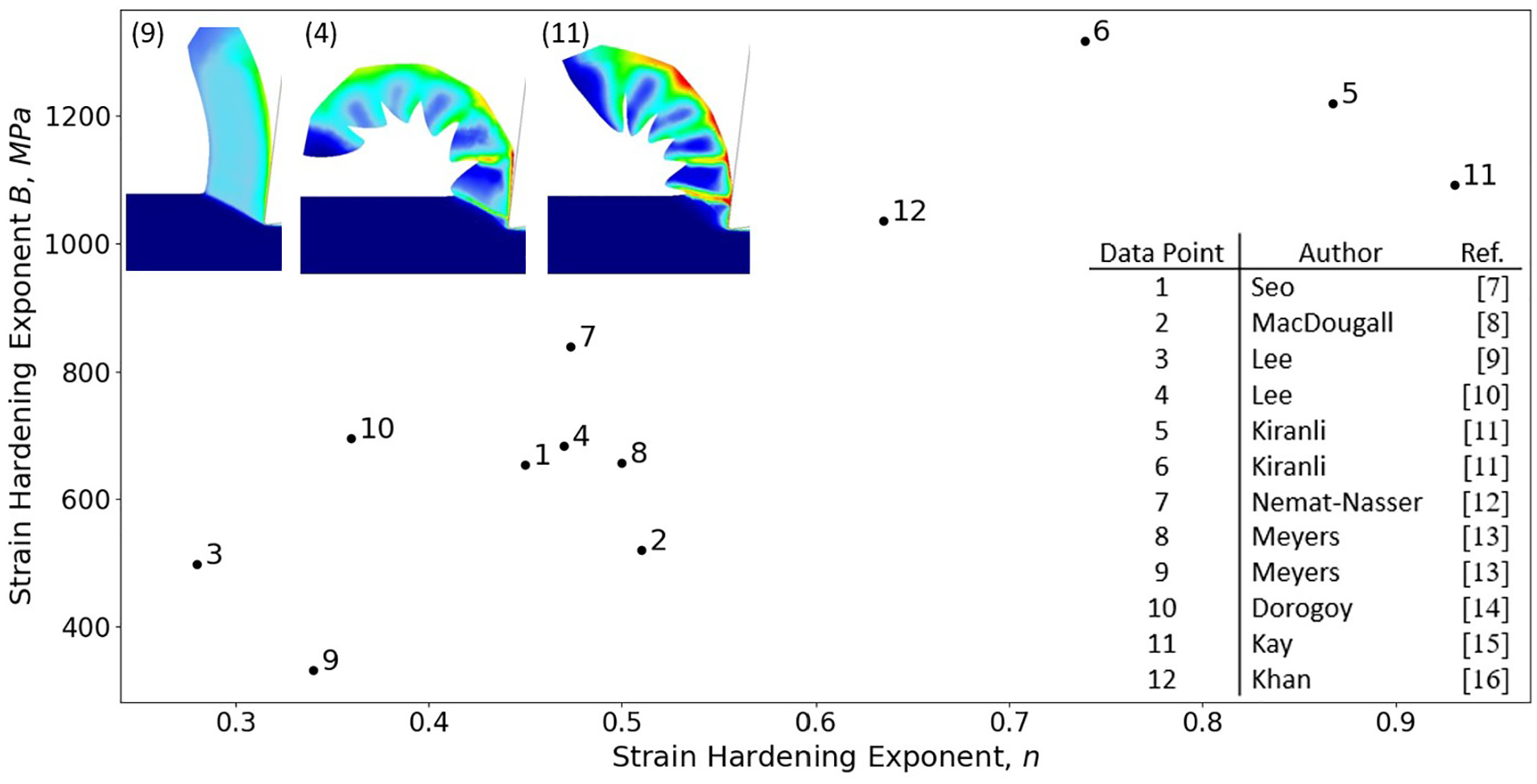
The reported strain hardening characteristics for Ti-64 range from close to perfectly plastic in nature, 13 to that approaching linear hardening. 15 This results in a change in the chip characteristics from continuous to fully serrated, meaning that obtaining accurate material parameters to represent the microstructural condition is crucial. This further supports the need for a rapid, small-scale, testing approach, designed to screen emerging titanium alloy compositions and conditions at an early stage, to inform the FE models, similar to how a microhardness test is used to quantify the resistance of a material to plastic deformation.
A review of the literature reveals two methods for obtaining the material modelling parameters. The first method uses orthogonal cutting to obtain key chip characteristics which are inputted into predictive models to obtain the flow stress data. Oxley 17 was one of the first researchers to suggest this method to obtain flow stress data, using an analytical model to predict the high strains, high strain rates and high temperatures encountered in machining using parallel-sided shear zone theory. Subsequently, authors have used this methodology: Shatla et al. 18 used Oxley’s theory to model orthogonal milling. They identified the JC material parameters by inverse analysis and demonstrated applicability in numerous alloys. Molinari et al. 19 presented an analysis for the development of adiabatic shear bands from orthogonal cutting of Ti-64, across a range of cutting speeds from 0.01 to 73.0 m s−1. This work was later used by Miguélez et al.20,21 to develop an FE model of the chip forming process and of the residual stresses produced during orthogonal cutting based on the JC model. Bai et al. 22 offered a chip forming model but used the Calamaz-modified JC model, again based on orthogonal cutting data. Zhou et al. 23 also developed their own FE model using a modified JC model for cutting titanium alloy Ti-6Al-4V, to improve the accuracy of predicted cutting forces and chip formation. Nasr et al. 24 investigated the effects of workpiece thermal properties on machining induced residual stresses through the use of FE modelling. Cotterell and Byrne25,26 utilised a high-speed camera during orthogonal cutting to rapidly obtain key chip characteristics; however, practicalities such as imaging frame rate and accessibility provided challenges for this technique. Laakso and Niemi 27 presented their work on determining the material model parameters from orthogonal cutting experiments; however, they advised that compression tests should be used in conjunction with cutting experiments as they offer the ability to change the key variables, strain, strain rate and temperature independently.
An early test by Hastings et al. 28 used high-speed compression tests to predict a material’s machining characteristics, including chip form and cutting forces. Since then the split-Hopkinson pressure bar test has been used to produce simple flow stress curves at different temperatures, strains and strain rates to generate accurate and reliable material data for the JC model.9,29–32 These tests have often been complimented with orthogonal cutting experiments to validate the FE simulation results, with significant focus aimed at accurately describing the chip geometries and cutting forces. However, up until now, the literature has not discussed machinability more broadly in conjunction with uniaxial compression tests.
This work proposes a novel low-cost methodology utilising the arbitrary strain path (ASP) test rig in Figure 2(a), produced by Servotest and developed at the University of Sheffield. The ASP produces a uniaxial load which lowers a test piece towards a bespoke tooling fixture to create an orthogonal cut. The small-scale orthogonal cutting test developed in this work was based upon an approach by Sutter; 33 however, the limitation of their work was that no load data could be recorded.
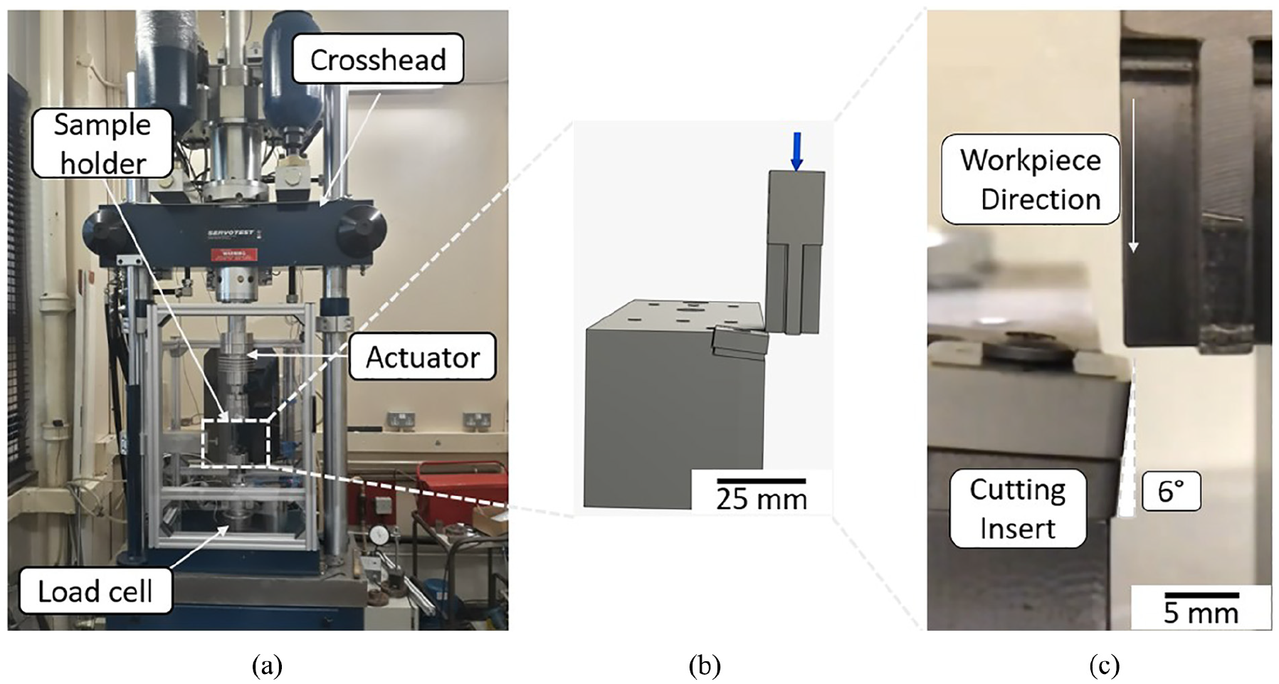
(a) Photograph of the ASP rig used for the small-scale cutting experiments, (b) 3D model of the tool holder designed and developed using Autodesk and (c) a photograph showing the negative 6° rake angle between the workpiece and the cutting insert.
The testing method has been designed to inform the manufacturing supply chain of material data at an early stage in the alloy design process. It can provide information on mechanical data and machinability data from just a small volume of material. At the very early development phase, new alloy compositions are vacuum arc melted into small ingot <300 g ‘buttons’ prior to partial forging and hot rolled into approx. 200 mm long bars for testing and analysis. The use of the ASP small-scale testing approach was developed (with the titanium machining supply chain) in order to rapidly assess the machinability of such early stage compositions. This article demonstrates that machinability with respect to chip formation, subsurface damage, tool wear and force data are typical of what could be expected during large-scale machinability experiments.
Methodology
Small-scale orthogonal cutting
As-forged Ti-6Al-4V (Ti-64) and Ti-3.9V-0.25Fe-0.85Al (Ti-407) billet material was supplied by TIMET UK of diameter of 225 mm. The material was subsequently wire electrical discharge machined (EDM) from the centre of the cross-section of the billet to the dimensions of 60 mm × 20 mm × 20 mm. Following this, the Ti-64 was put through a mill annealed (MA) treatment and the Ti-407 was solution treated and aged (STA). The mediums for solution treatment included air, oil and water, to generate different cooling rates, and therefore specific microstructures and α/β morphologies for each alloy. The microstructures for each of the heat treatments are shown in Figure 3. The test pieces were machined again to a final geometry of 50 mm × 15 mm × 15 mm. The lower 30 mm of the samples were machined to a ‘cross’ geometry with each section of the ‘cross’ profile being machined to a width of 4 mm, as shown in Figure 4. The bespoke insert holder was designed to clamp Seco Tools SNMA150616-MR9 cutting inserts. A square insert was used for two reasons: first, for the ease of manufacturing a bespoke tool holder as a proof of concept for using the ASP as part of the methodology, and second, to handle the high forces exerted on the tool edge. The insert material was uncoated (WC–6% Co) tungsten carbide substrate with a cobalt binder phase. The orthogonal set-up comprised a negative 6° rake angle, as illustrated in Figure 2(c). The tests were performed at a constant speed of 6.0 m min−1 with an uncut chip thickness of 0.3 mm which was measured to within 10% of the expected value using a digital gauge indicator. The maximum cutting speed was limited by the available pressure in the pumps to move the actuators in a single cut. The length of the cut was 10 mm.
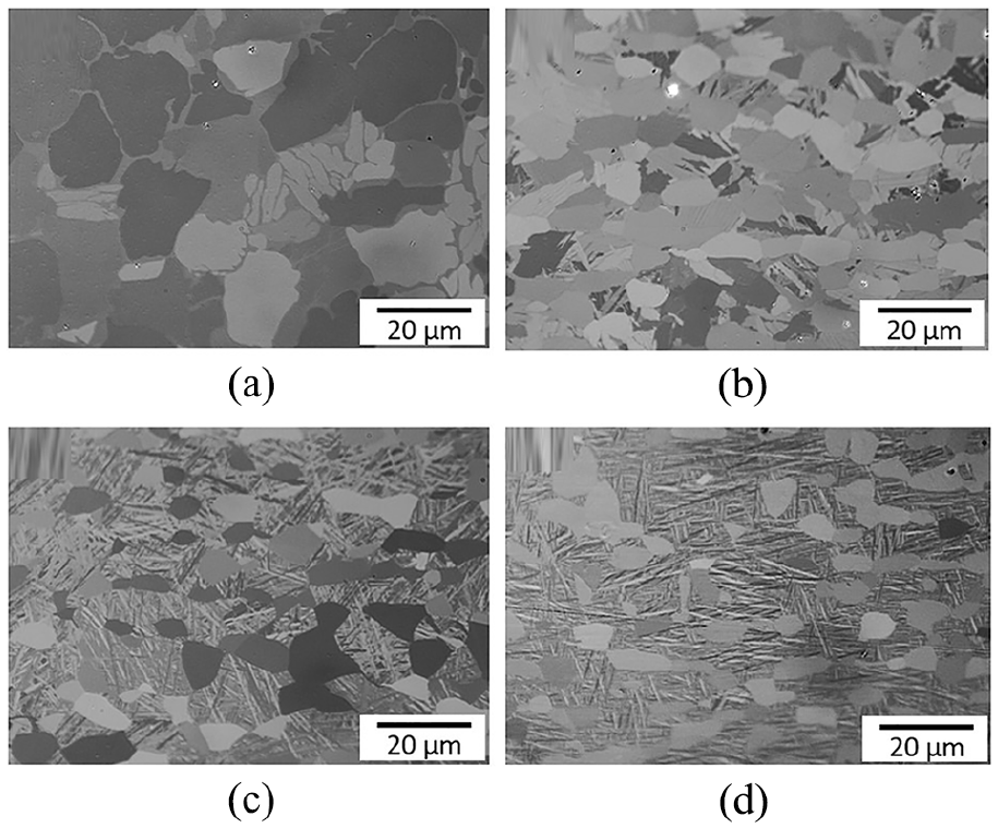
Micrographs of the titanium alloy test pieces used in this work post heat treatment: (a) Ti-64 MA, (b) Ti-407 STA air cooled, (c) Ti-407 STA oil quenched and (d) Ti-407 STA water quenched.
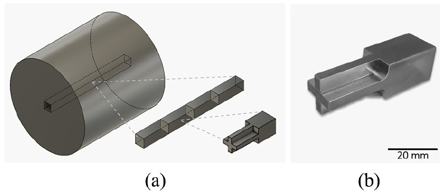
(a) Location of and geometry of the test samples used for the small-scale orthogonal cutting tests and (b) a photograph of the sample used for the small-scale orthogonal cutting test.
Diffusion couple experiment
The diffusion couple method consists of a titanium alloy coupon of size 20 mm × 20 mm sat underneath an uncoated (WC–6% Co) tungsten carbide, Seco Tools SNMA150616-MR9 insert, with an Inconel weight placed on top to provide pressure. Prior to testing, the titanium alloy test pieces were polished to a mirror finish using conventional methods and ultrasonically cleaned in isopropanol. The test piece, tool and nickel weight stack were placed on a ceramic cradle inside the vacuum furnace. The chamber was pumped to a pressure of 10−5 mbar. Following this, the furnace was heated slowly at a steady rate of 3°C min−1 and held for 2 h at 1000°C before being cooled down to room temperature. After the heating process, the titanium alloy and the insert were set in an epoxy resin mould to protect the bond, before being carefully sectioned. Metallographic preparation was conducted again to achieve a mirror finish. The samples were analysed in a scanning electron microscope to reveal the thickness of the chemical diffusion bond. This work is a continuation of previous studies conducted by Hatt et al.4,5,34
Industrial cutting trials
To validate the small-scale methodology, industrial-scale machining tests were also conducted on the same alloy conditions and some commonalities between the tests have been highlighted. Turning operations were conducted on a DMG Mori NLX 2500 CNC machine turning centre at the University of Sheffield’s, Advanced Manufacturing Research Centre (AMRC), with an experimental set-up as shown in Figure 5. Cutting tools used were WC–6% Co, TNMG160408-MF1, uncoated inserts. The inserts used in the industrial cutting trials are not identical in shape to the small-scale orthogonal cutting inserts; however, they are of the same substrate grade, so the machining characteristics of both alloys should be representative, irrespective of the tool. A PTJNL2525M16 tool holder was modified by wire EDM to offset tool angles back to orthogonal and like the small-scale cutting trials maintain a negative 6° rake angle. An outer ring of width 4 mm was grooved out using an internal grooving tool and an LCMF160608-0600-FT insert with a CP500 coating. The width of the region used for the orthogonal machining tests was measured to 4 mm ± 0.05 mm using a ball micrometre, as illustrated in Figure 6.
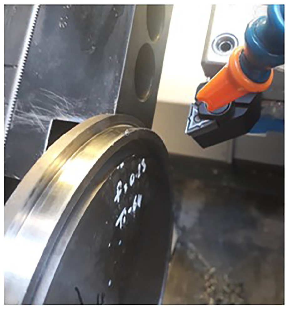
Photograph showing the set-up for the industrial machining trials. Using a disc of material held inside a CNC machining centre; the cutting insert held into a dynamometer to record the cutting forces and the coolant provided through an external pipe.
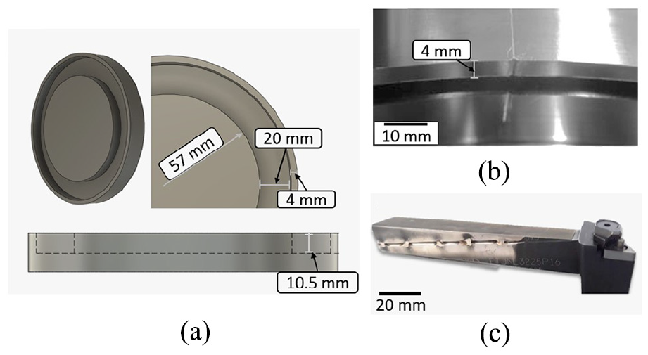
(a) 3D CAD illustration of the workpiece after grooving the disc to form a 4 mm wide ring for orthogonal machining trials, (b) photograph of the 4 mm wide ring for orthogonal cutting trials and (c) photograph of the modified tool holder, wire EDM to meet the requirements for orthogonal machining.
Results and discussion
Room temperature uniaxial compression tests were performed at four strain rates ranging from 0.1–100 s−1. Figure 7 contains a series of flow stress graphs for strain rate tests of 0.1, 1.0 and 10 s−1. The measurement frequency was too low to measure 100 s−1, so the flow stress data have not been presented.
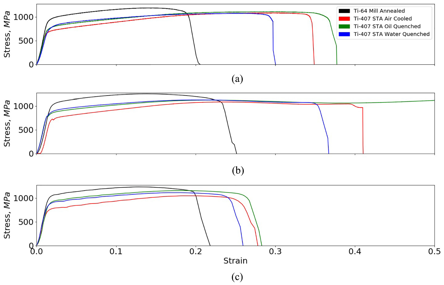
Flow stress curves produced from the compression tests at strain rates of (a) 0.1 s−1, (b) 1.0 s−1 and (c) 10 s−1.
Figure 7 shows that the test samples fractured in all of the tests at strain rates 0.1 and 10 s−1, except for the Ti-407 oil quenched at a strain rate of 1.0 s−1. Without further testing at higher strains, this cannot be explained, although the Ti-407 oil quenched sample did show signs of plastic instability and imminent failure due to intense shear band in the macrostructure. Nevertheless, the main point from Figure 7 is that the observed trends between strain rates and conditions are in strong agreement. The Ti-64 accommodated less strain than Ti-407 at all strain rates tested. The maximum measured stress was higher in Ti-64 than Ti-407 across all strain rates, this agrees with our knowledge of the two alloys from James et al., 35 that Ti-64 is a stronger alloy, so can accommodate greater stress at the point of fracture. The area under the curves, presented in Table 1, is a good approximation of the toughness and work done prior to fracture of the alloys. At the strain rate of 0.1 s−1, the Ti-407 water quenched test sample has a lower toughness compared to the Ti-407 air cooled one; however, increasing the strain rate to 10 s−1, the reverse trend is observed. Cross-sections of the test samples in Figure 8 compliment the results displayed in Figure 7 and Table 1, to document the level of fracture of Ti-64 compared to the ductile behaviour of Ti-407. Comparing the Ti-407 STA processed through different solution treatment mediums, the process of oil quenching greatly enhanced the toughness of the Ti-407 alloy, accommodating a greater amount of strain before fracture.
Comparison of the toughness of each titanium alloy, measured as the area under the flow stress curve.
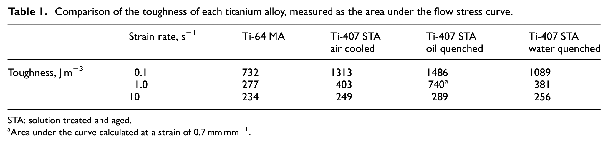
STA: solution treated and aged.
Area under the curve calculated at a strain of 0.7 mm mm−1.
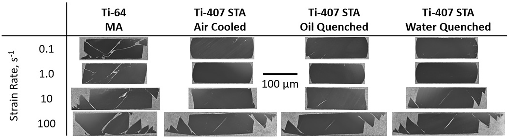
Map of photographs showing the cross-section of the titanium alloys, from a strain rate of 0.1–100 s−1, after testing has been completed.
As Ti-407 was developed as an alloy to replace Ti-64 in applications where energy absorption during fracture is a primary design consideration, 35 it is expected that the alloy exhibits higher toughness through accommodating greater strain than Ti-64. From these results, the relative chip forming characteristics of Ti-64 and Ti-407 can be predicted.
The flow stress data from the compression tests at a strain rate of 0.1 s−1 was used to develop a DEFORM™ 36 model to predict the relative strain and chip form for room temperature orthogonal cutting tests of these alloys. The model makes some assumptions including (1) a rigid–viscoplastic workpiece and (2) a rigid tool. The Norton–Hoff model, shown in equation (1), was used for this study, as the JC model exhibits a flow stress increase with increasing strain at any temperature. Researchers37,38 have confirmed that the JC model cannot predict the adiabatic phenomenon responsible for the segmented chip formation as the thermal softening effects are not taken into account. The Norton–Hoff equation assumes perfect viscoplasticity; therefore, it fails to examine the effect of the elastic behaviour of the material. Cockroft and Latham (C&L) 39 was used for the damage criterion model in order to obtain a segmented chip geometry
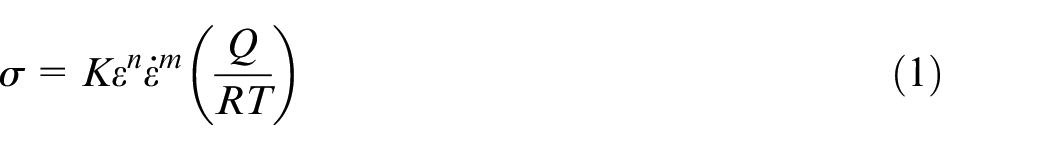
where K is a constant, n is the strain hardening exponent, m is the strain rate sensitivity parameter, Q is the activation energy, R is the ideal gas constant and T is the temperature. To obtain the K, n, m and Q/R parameters, a multiple linear regression was used. With the material parameters from Table 2, a simple two-dimensional (2D) uniaxial compression test was simulated using DEFORM, with the results presented in Figure 9. The C&L damage criterion was measured at the point at which fracture occurred in the compression tests. The model agrees with the experimental compression tests, showing that at the point of fracture, the effective strain is lower in Ti-64 than in Ti-407. The effective strain for the oil quenched model was over double that of Ti-64. This means that more strain has to be accommodated in the material for fracturing of the chip to occur. Comparing Figure 9 with the toughness values in Table 1, it is evident that the larger compression and higher strain values in the FE compression models of Figure 9 are validation of the enhanced toughness of the Ti-407 compared to Ti-64. The ability of a material to plastically deform to higher strains prior to fracture is a key property of an alloy designed to absorb significant loads before fracturing; however, this indicates that the machined chip form will be inherently more ductile in such an alloy.
Norton-Hoff model material parameters from flow stress curves at a strain rate of 0.1 s−1.
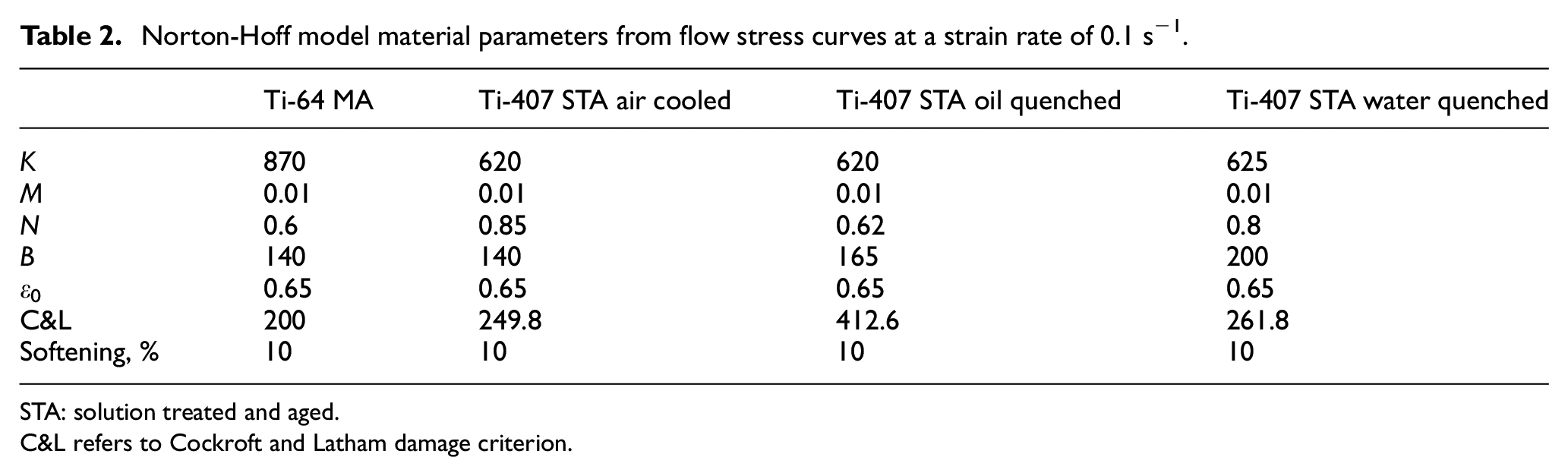
STA: solution treated and aged.
C&L refers to Cockroft and Latham damage criterion.
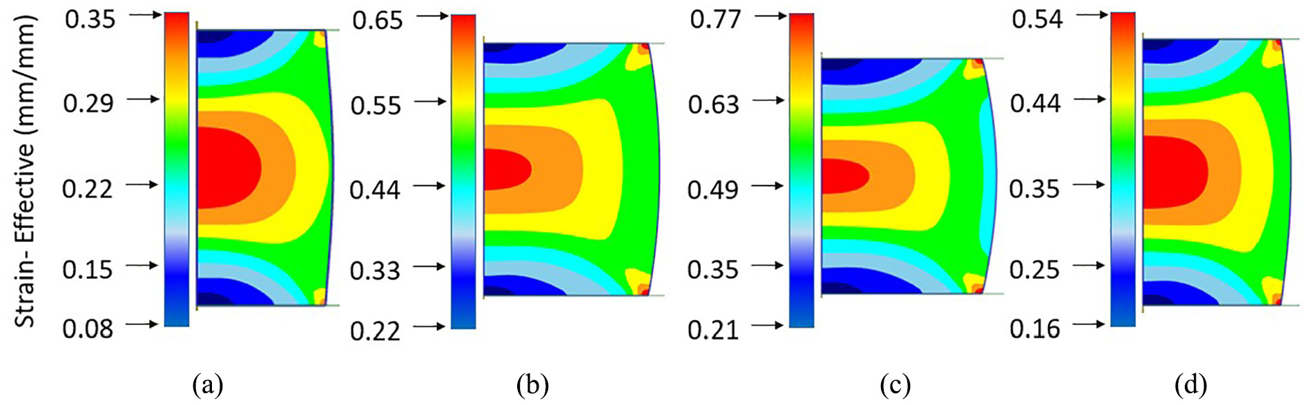
DEFORM™ compression simulations showing the effective strain across the cross-section of the test pieces at the point of fracture at a strain rate of 0.1 s−1. The material data used is as shown in Table 2. (a) Ti-64 MA, (b) Ti-407 STA air cooled, (c) Ti-407 STA oil quenched and (d) Ti-407 STA water quenched.
Using the same material parameters from the DEFORM uniaxial compression tests, a 2D orthogonal cutting test was simulated, to predict the chip forming characteristics of the test samples. The model was set up to closely replicate the cutting conditions of the small-scale orthogonal cutting tests, using a cutting tool with a chip breaker and a negative 6° rake angle, depth of cut of 0.3 mm and a cutting speed of 6.0 m min−1. There is strong agreement between the DEFORM chip forming models in Figure 10 and both the experimental compression tests and the DEFORM compression models in Figures 7 and 9, respectively. Ti-64, which accommodates less strain prior to fracture, forms a segmented chip. The chip form for Ti-407 varies hugely from one microstructural condition to the next. The higher strain accommodation in the Ti-407 oil quenched chip resulted in the formation of a continuous chip. The simulations shown in Figure 10 predict that the Ti-64 would form a high-frequency segmented chip. The Ti-407 samples by contrast range from a segmented chip of moderate frequency to a fully continuous chip. Presence of adiabatic shear bands can be postulated from the fluctuations in the cutting forces shown in Figure 11(a), which can be attributed to the thermal softening and strain hardening of the forming chip. One of the reasons for the lower regularity of segmentation of Ti-407 is due to its higher thermal conductivity, 35 which is almost double that of Ti-64 at room temperature. Bäker et al. 40 studied the influence of thermal conductivity on the chip segmentation process, finding that the degree of segmentation reduced as thermal conductivity increased. The Ti-407 has far lower cutting force peaks, implying that the adiabatic shear bands are wider than Ti-64 surmising that the chip forming and breakability of the alloy are much more challenging to manage. Furthermore, with greater strain accommodated in the chip, more subsurface features such as severe plastic deformation and mechanical twinning can be retained in the machined surface.
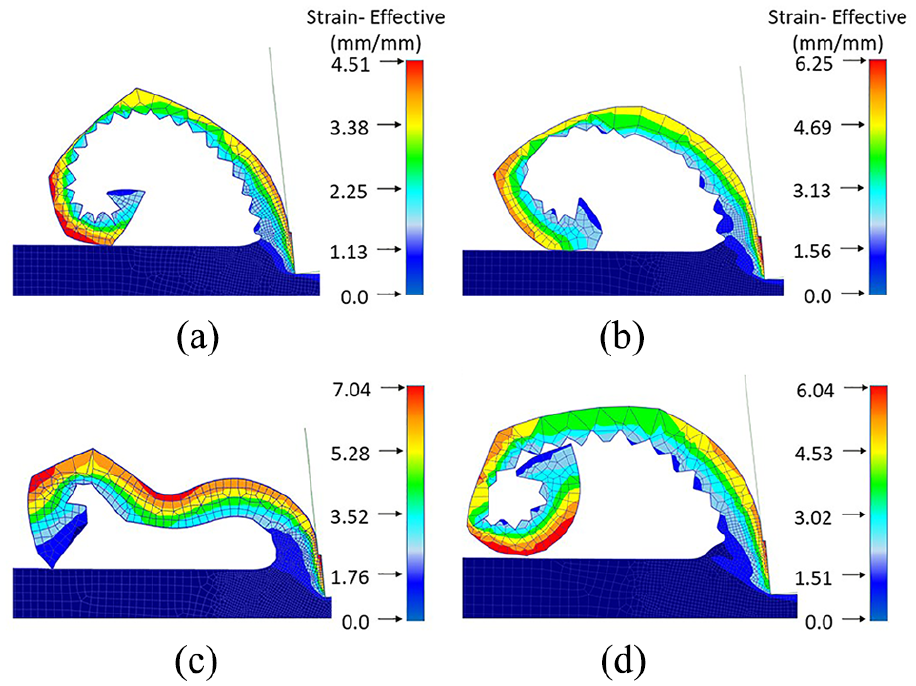
DEFORM orthogonal 2D simulations showing the chip forming characteristics for each of the corresponding alloys based on material data modelled in the DEFORM compression simulations at a cutting speed of 6.0 m min−1: (a) Ti-64 MA, (b) Ti-407 STA air cooled, (c) Ti-407 STA oil quenched and (d) Ti-407 STA water quenched.
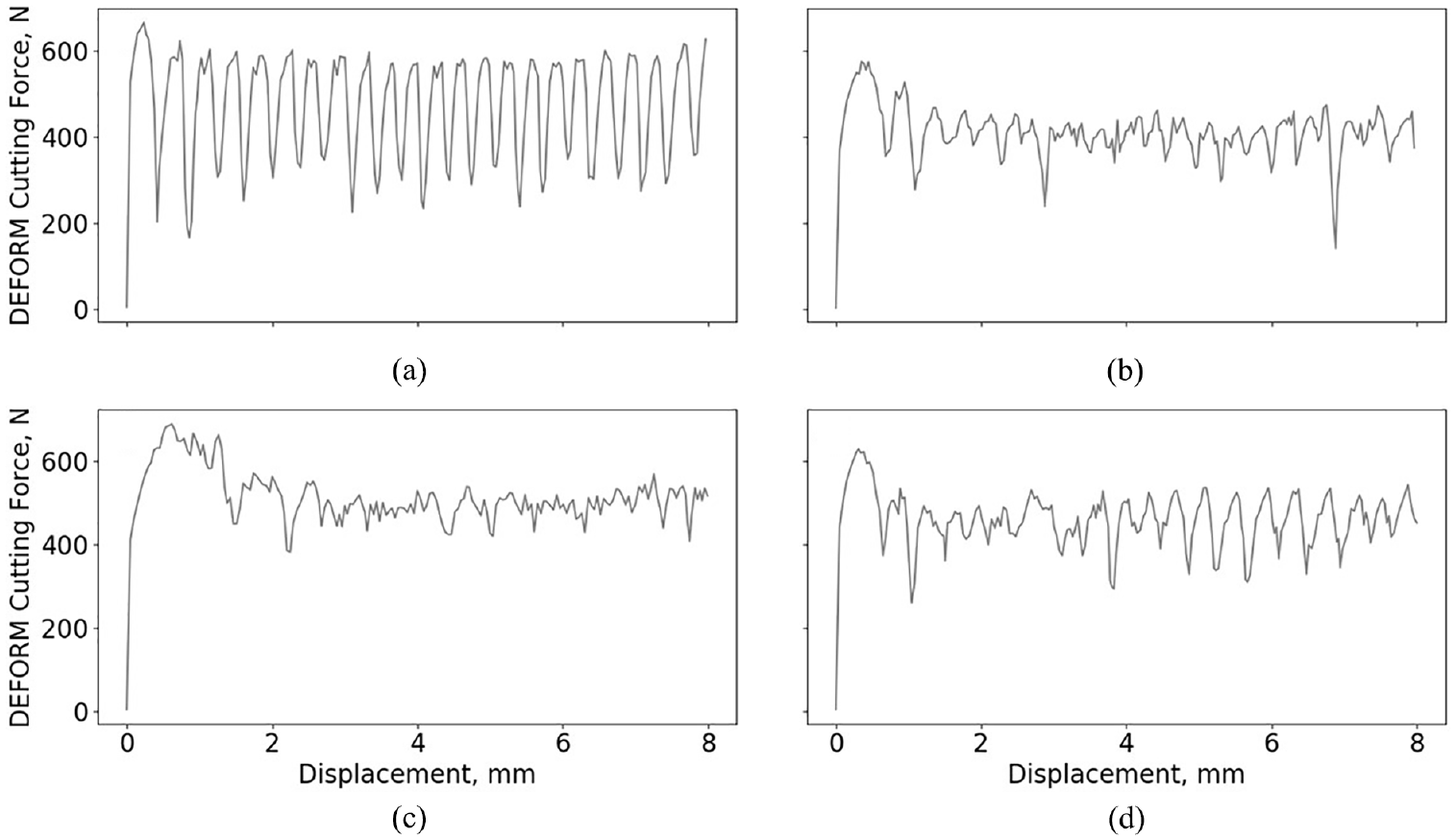
Figure of DEFORM 2D orthogonal cutting simulations showing the cutting forces required to form a chip for (a) Ti-64 MA, (b) Ti-407 STA air cooled, (c) Ti-407 STA oil quenched and (d) Ti-407 STA water quenched.
Figure 12 shows in situ photographs from the small-scale orthogonal cutting tests, which under identical conditions shows marked differences between the test alloys. There is good agreement between the experimental results and the FE orthogonal cutting models. Ti-64 in Figure 12(a) forms a segmented chip at regular intervals which analysed closely in the micrograph of Figure 13(a) shows that each chip segment is of consistent geometry and pitch, with formation of narrow shear bands between each. The Ti-407 oil quenched test piece forms almost a continuous chip which is comparable to the predicted chip modelled in Figure 10(c). Some researchers41,42 believe that there is a critical cutting speed when a continuous chip form ceases and a serrated, shear localised chip dominates. This theory is based on a purely thermally activated process; when cutting speed decreases to a ‘critical value’, the deformation becomes uniform and the distance between the shear bands approaches zero because the thermal gradient is negligible. 43
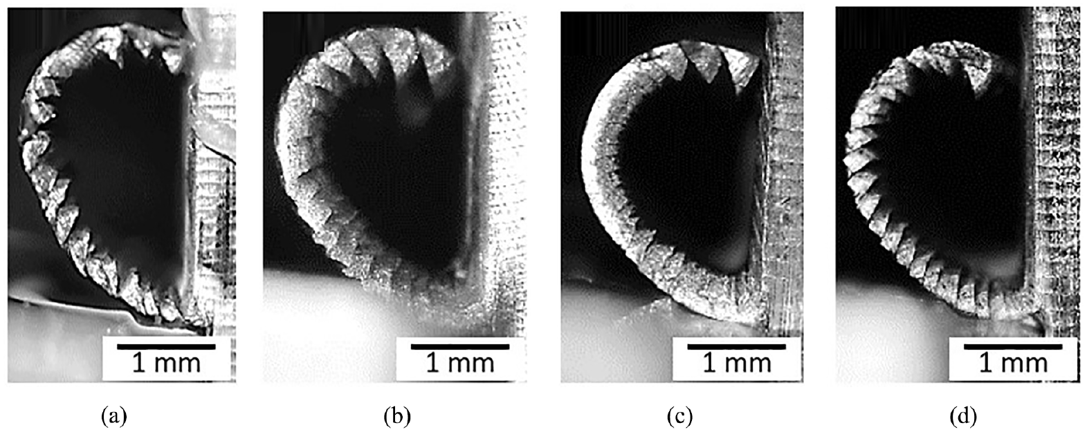
In situ photographs taken with a Nikon D5000 camera of the chip forming process from the small-scale orthogonal cutting tests: (a) Ti-64 MA, (b) Ti-407 STA air cooled, (c) Ti-407 STA oil quenched and (d) Ti-407 STA water quenched.
Cross-sectional light micrographs of the chip formation from the small-scale orthogonal cutting tests for (a) Ti-64 MA, (b) Ti-407 STA air cooled, (c) Ti-407 STA oil quenched and (d) Ti-407 STA water quenched.
There is no discernible shear band in the Ti-407 oil quenched sample, showing that a uniform temperature gradient was present across the chip during the cut. The experimental cutting forces in Figure 14 show similar trends to the FE orthogonal cutting simulations, where the height of the peaks is greatest for Ti-64 MA and smallest for the Ti-407 oil quenched. There is a sudden rise in the force output of the Ti-407 oil quenched, which will be discussed in the following section looking at tool wear.
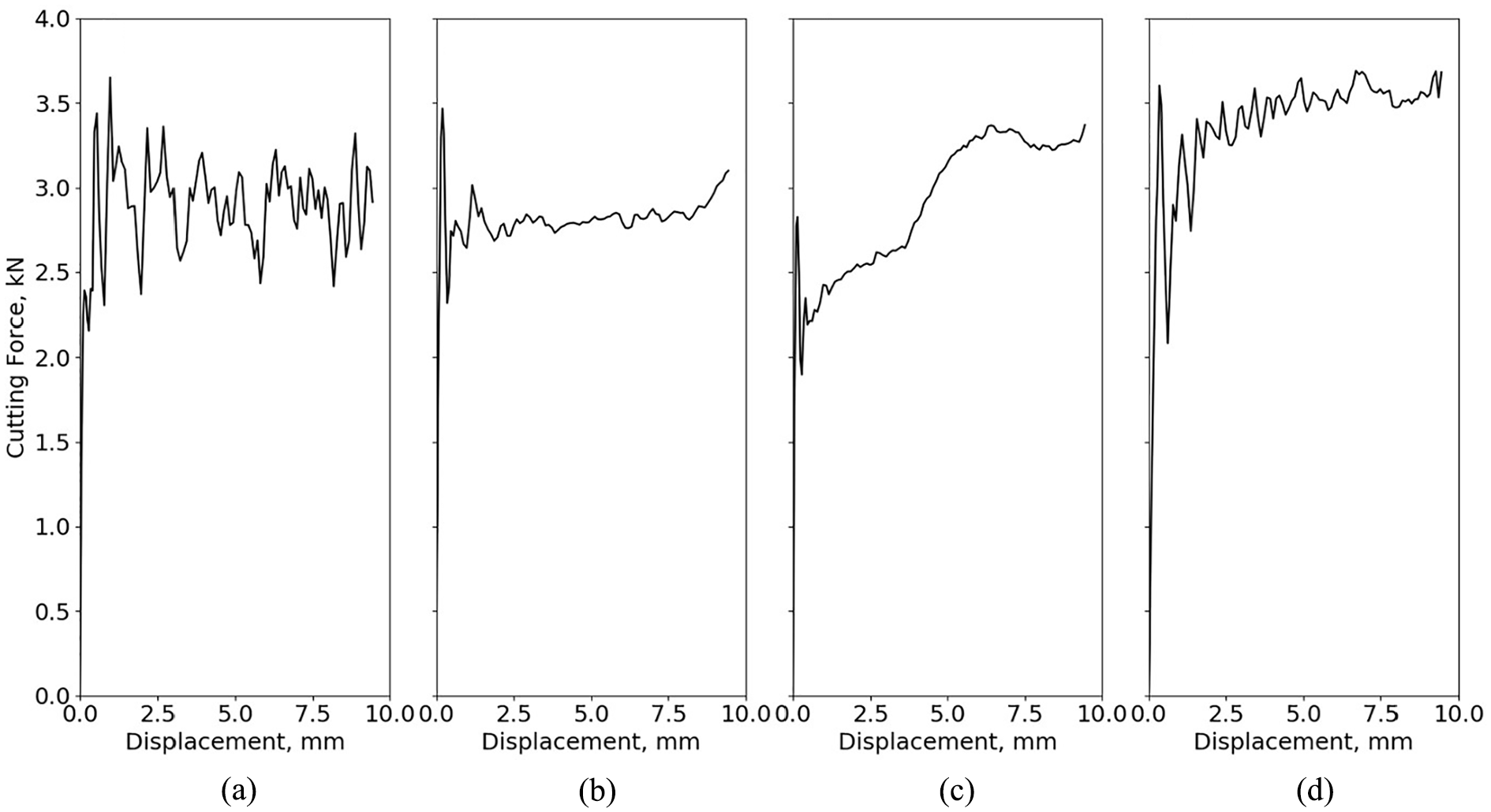
Experimental cutting forces measured from the small-scale orthogonal cutting for (a) Ti-64 MA, (b) Ti-407 STA air cooled, (c) Ti-407 STA oil quenched and (d) Ti-407 STA water quenched.
Up to this point, the results have focused on the small-scale experimental work and modelling study. The industrial cutting tests have been requisite to validate the small-scale experimental work and provide some relatability to industry. Figure 15 shows the chip form of both Ti-64 and Ti-407. Similarly to Figure 13, the Ti-64 forms a segmented chip, with large peaks and narrow shear bands; conversely, the Ti-407 forms chip segments with very small peaks and a continual shear band straining perpetually into the following section of the chip. Relating these observations to the overall machinability of the materials with a focus on chip breakability, it is apparent from Figure 16 that the Ti-64 MA chip is easier to manage and control compared to Ti-407 across a range of cutting speeds. Based on flow stress data and chip form characteristics, these results were predicted in the first part of this investigation with the compression tests and 2D orthogonal model.
Cross-sectional light micrographs of the chip formation from the industrial cutting tests for (a) Ti-64 MA and (b) Ti-407 STA water quenched.
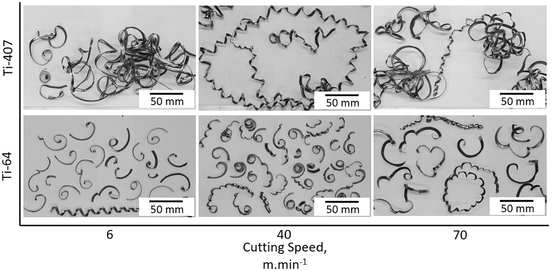
Photographs showing the comparable chip formation at cutting speeds (6, 40 and 70 m min−1) from the industrial orthogonal cutting tests of Ti-64 MA and Ti-407 STA water quenched. Feed rate = 0.3 mm rev−1.
In addition to reliable chip morphology, subsurface features have been obtained to support the work comparing small-scale cutting and industrial-scale cutting. Analysis of subsurface features is of paramount importance with features like white layer being rejected for aerospace components. Therefore, being able to inform on the relative damage tolerance of one alloy against another during the development phase is essential. Previous studies2,44 have shown that microstructural modifications in the subsurface of the titanium alloy are induced by machining parameters.
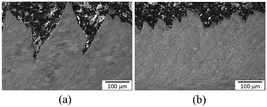
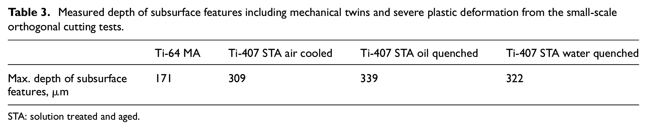
In this work, subsurface features were characterised as severe plastic deformation and mechanical twinning. Under the same cutting conditions, the Ti-64 was able to tolerate the effects of machining more than Ti-407. Table 3 and Figure 17 show that the measured depth of subsurface features in the Ti-407 was almost double that of Ti-64 with mechanical twins being the predominant feature. Similarly, Figure 18 shows the same trends for industrial cutting tests. Twin formation in Ti-64 occurred randomly across the surface of the alloy, likely due to variations in the grain orientation with certain grains being more favourable to slip. The Ti-407 however consistently formed a dense region of mechanical twins just below the machined surface. The mechanical twins provide a mechanism for the material to accommodate more strain before fracture occurs which is an idea put forward by Kloenne et al. 45 to explain the improved ductility of Ti-407.
Measured depth of subsurface features including mechanical twins and severe plastic deformation from the small-scale orthogonal cutting tests.
STA: solution treated and aged.
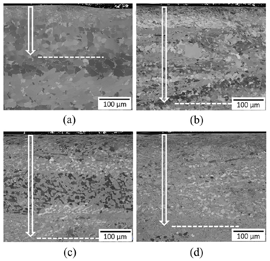
Light micrographs of the depth of subsurface features from the small-scale orthogonal cutting tests: (a) Ti-64 MA, (b) Ti-407 STA air cooled, (c) Ti-407 STA oil quenched and (d) Ti-407 STA water quenched.
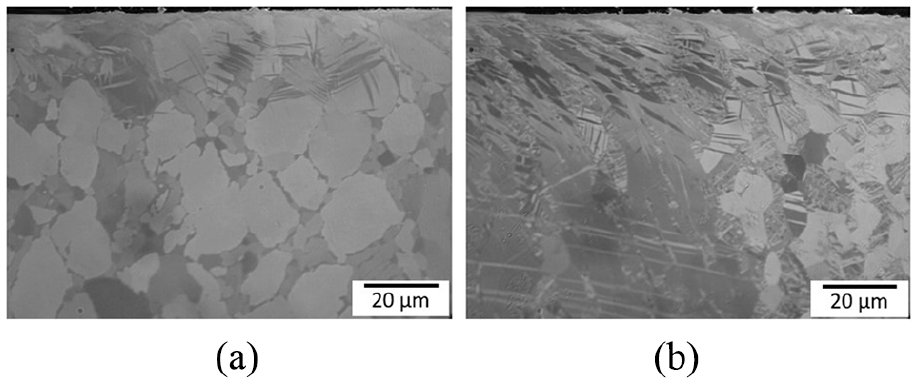
Light micrographs of the depth of the subsurface features from the industrial cutting trials: (a) Ti-64 MA and (b) Ti-407 STA water quenched.
The average cutting forces for Ti-64 MA and Ti-407 STA water quenched have been presented in Figures 19 and 20 for both the small-scale orthogonal cutting and the industrial cutting trials, respectively. The figures are significant as they show particular trends for each alloy. As the cutting speed increases, Ti-64 average cutting forces increase in agreement with other authors 46 whereas for Ti-407 these forces decrease, which shows that the relationship between thermal softening and strain hardening for each alloy is uniquely different. Predictions on tool wear can also be implied from these results as well. It would be prudent to assume that with the decreasing cutting forces, the stresses acting on the tool would also be reduced and tool wear mechanisms would change. Ti-407 would likely develop more built-up edge (BUE) across the tool edge, from the softening of the workpiece; Ti-64 would likely experience the effect of more mechanical wear types as the stresses on the tool increase, through the likes of notch wear, chipping and crater wear.
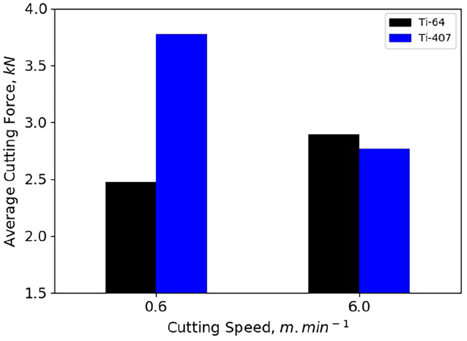
Bar plot showing the average cutting force in comparison to the cutting speed for the small-scale orthogonal cutting tests for Ti-64 MA and Ti-407 STA water quenched cooled.
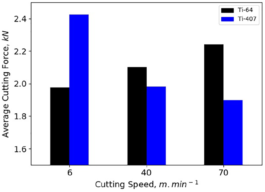
Bar plot showing the average cutting force in comparison to the cutting speed for the industrial cutting tests for Ti-64 MA and Ti-407 STA water quenched.
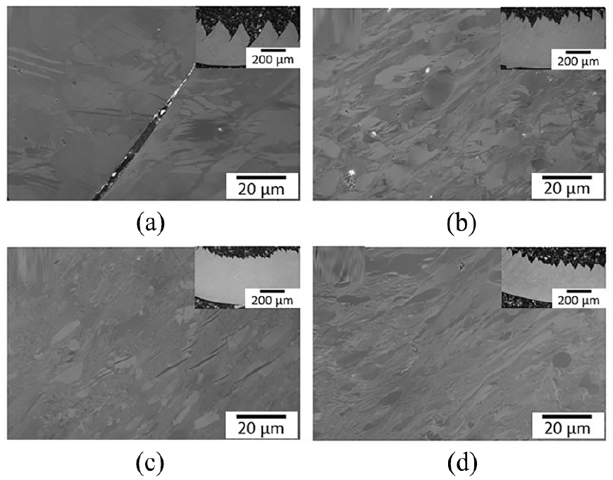
Crater wear, a wear mode recognised as detrimental to the life of a tool due to the high chemical reactivity of titanium alloys has been investigated previously.4,5,47 Hatt et al.4,5 developed a low-cost static diffusion couple experiment that could predict the complex reaction mechanisms that occur at the tool–chip interface during high-speed machining of titanium alloys. The methodology developed by Hatt et al. 4 was replicated in this study to investigate the chemical reactivity of the alloys. All of the alloy samples formed a strong diffusion bond with the tool. Figure 21 shows a dark region in between the tool and alloy which was determined to be a layer of TiC. This idea is further strengthened by Figure 22 which demonstrates through the utilisation of energy-dispersive X-ray spectroscopy (X-EDS) analysis a highly concentrated region of carbon in between the tool and the workpiece. The thickness of the TiC layer is larger for the Ti-407 compared to the Ti-64. The micrographs agree with Hatt et al., 5 whereby increasing beta content and thus the molybdenum equivalency of an alloy, decreases the thickness of the TiC layer. The molybdenum equivalency for the two alloys in this investigation, Ti-64 and Ti-407, has been calculated as 3.7 and 3.2, respectively. The TiC layer acts as a protective coating reducing the susceptibility of chemical wear. Based on this knowledge, the tool life for Ti-407 should be better than that of Ti-64 due to the lower chemical reactivity and the greater formation of TiC across the rake face.
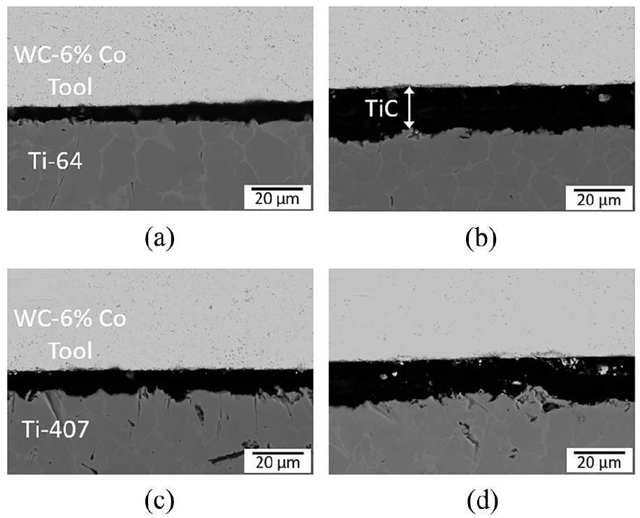
Scanning electron micrographs of the TiC interface between WC–6% Co cutting insert and workpiece material from diffusion couple experiments: (a) Ti-64 MA, (b) Ti-407 STA air cooled, (c) Ti-407 STA oil quenched and (d) Ti-407 STA water quenched.
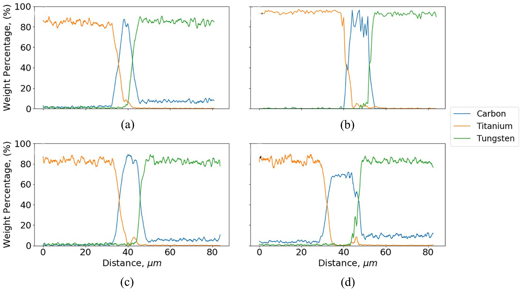
X-EDS analysis showing the titanium, tungsten and carbon across the tool and workpiece, including diffusion bond region: (a) Ti-64 MA, (b) Ti-407 STA air cooled, (c) Ti-407 STA oil quenched and (d) Ti-407 STA water quenched.
Tool wear images for the small-scale orthogonal and the industrial cutting tests pictured in Figures 23 and 24, respectively, show strong correlations between the two test methods. The Ti-407 oil quenched in particular is more susceptible than Ti-64 MA to BUE formation across the edge of the tool. The formation of BUE has been argued to act as a protective layer by forming work-hardened material across the edge of tool delaying tool failure.48–51 However, it significantly affects the rake angle of the tool 40 which has a further knock-on effect to the shape and length of the chip and the surface finish of the machined workpiece. Referring back to Figure 14(c), the rise in cutting forces could be attributed to the formation of the BUE shown in Figure 23(c). It would be beneficial to the tool life of Ti-407 to form a small layer of BUE in order to protect the tool from the effects of the alloys high chemical reactivity. Conversely, the higher thermal conductivity of the Ti-407 alloy should help protect the tool from crater wear longer than Ti-64, by promoting better heat transfer away from the tool, so lowering the rate of diffusivity of chemical elements at the tool–chip interface.
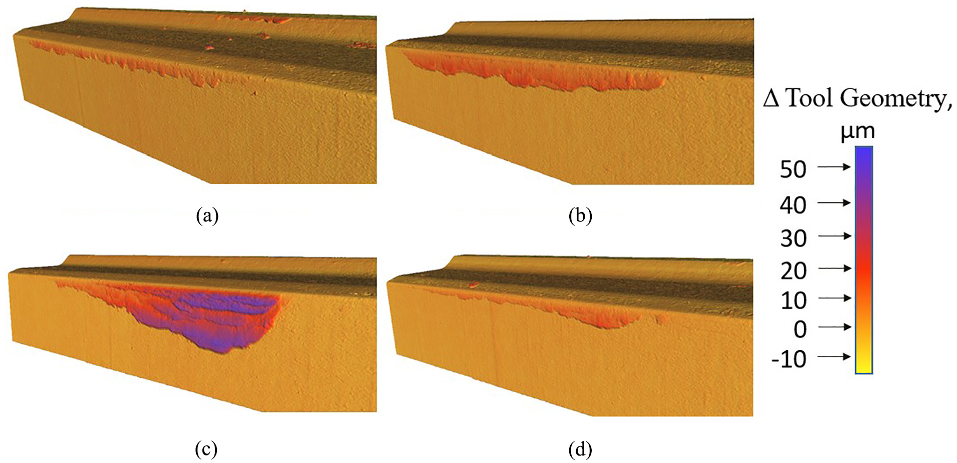
Alicona 3D scans of the tools from the small-scale orthogonal cutting tests showing the build-up of workpiece material across the edge of the tool for (a) Ti-64 MA, (b) Ti-407 STA air cooled, (c) Ti-407 STA oil quenched and (d) Ti-407 STA water quenched.
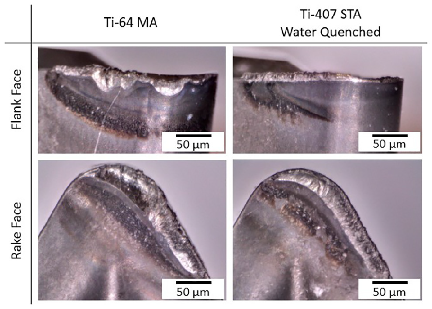
Photographs of the flank wear and rake face wear from tool life trials for Ti-64 MA and Ti-407 STA water quenched from large-scale turning trials at 80 m min−1.
It is necessary to place these results in a wider context. The small-scale methods are not to be a direct replacement for conventional, machining trials; simply an early stage filtering step exploited to efficiently down select compositions and microstructural conditions to generate new information for a material data sheet allowing machinability for different alloys to be compared. Table 4 provides an approximation of the costs associated with both the industrial cutting experiments and the small-scale testing methods to examine the machinability of Ti-64 MA and Ti-407 STA water quenched. These costs do not include the price of the finite element method (FEM) software licence, for the small-scale tests; however, it should be noted that as the machinability tests are for a preliminary exploration of a number of new compositions, the cost of the licence per simulated composition is minimal. The significant costs of machine time and technical support associated with the industrial cutting trials are attributed to the requirement for skilled personnel to operate the high energy-consuming machining centres and the extra resources required which add further cost to the cutting operation. The small-scale tests provide significant cost savings, in the order of approximately 90%, and provide key information about the relative machinability of titanium alloys.
Cost comparison for the testing Ti-64 MA and Ti-407 STA water quenched for the industrial cutting tests and the small-scale tests.
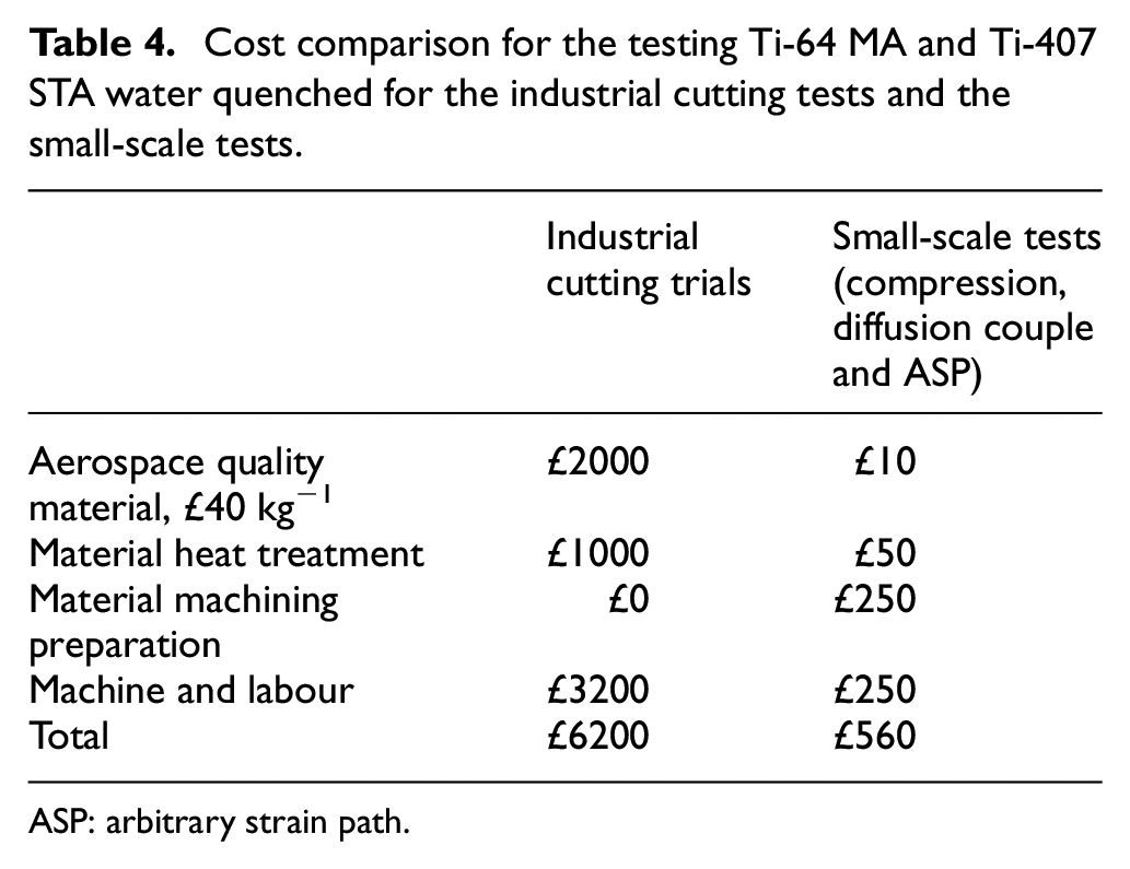
ASP: arbitrary strain path.
The small-scale tests coupled with the DEFORM models have been developed and ‘stress tested’ against full-scale turning trials to inform on key machinability outputs. The tests are shown to be intrinsically linked such that the machinability outputs of each level, presented in the schematic of Figure 25, can be inferred through completion of each of the other tests. The first level of experiments presented (the compression and the diffusion couple experiment) has provided an insight into the fundamental material and machinability data in particular flow stress, shear band formation characteristics and thermodynamic driving forces, directly correlating to the machinability variables, chip geometry characteristics, subsurface features and tool crater wear. Modelling the 2D chip form allows prediction of the relative strain accommodated in the titanium alloys, which again infers chip geometry characteristics, subsurface features and cutting forces of titanium alloys. The small-scale cutting experiments in stage 2 not only validate observations from stage 1 but also provide better resolution of chip form and subsurface damage characteristics. Importantly, the machinability characteristics captured for Ti-64 and Ti-407 using the low-cost machinability assessments were reliably observed in the industrial high-speed turning trials.
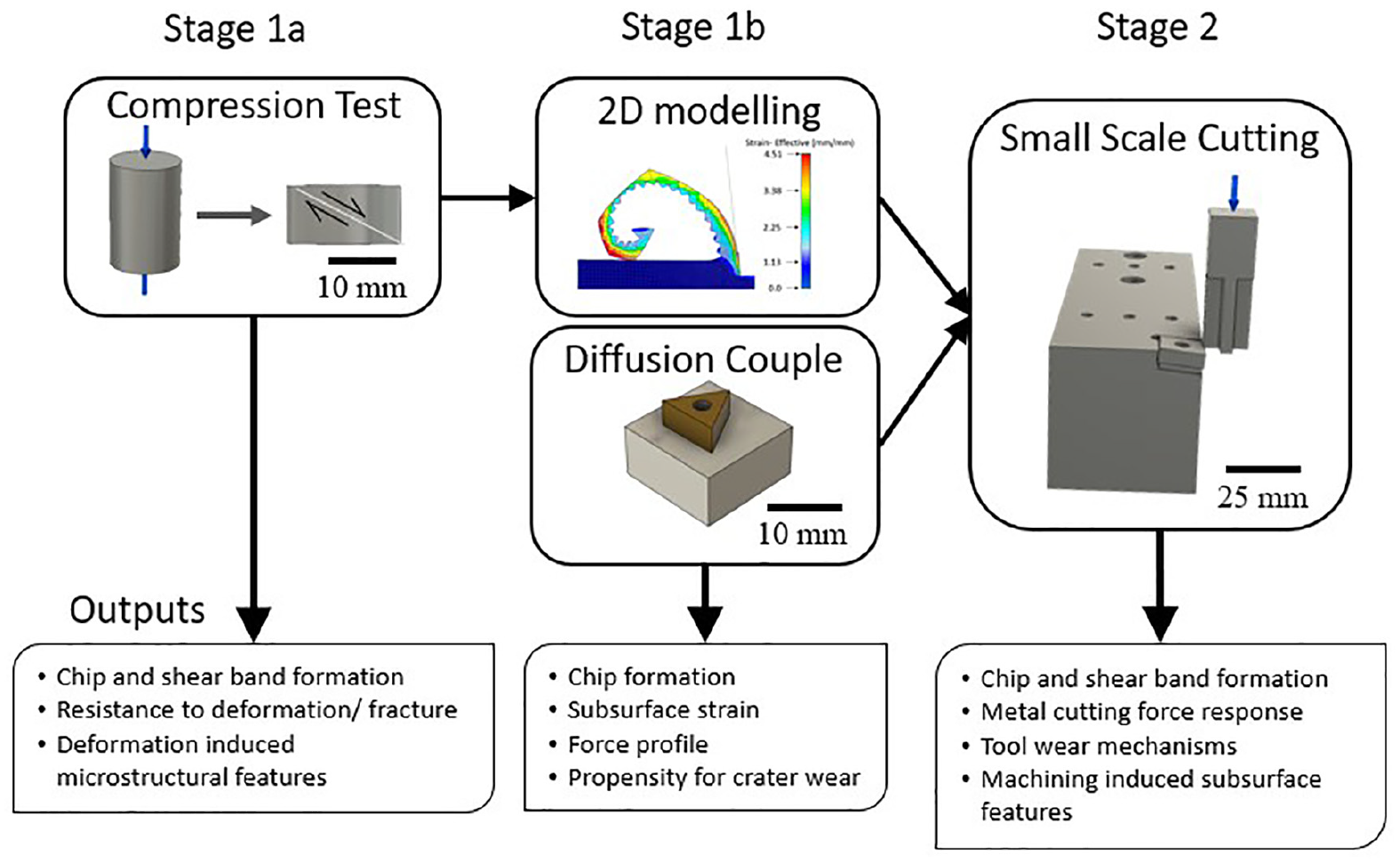
A schematic showing the suggested order for completion of the small-scale tests and modelling to filter out undesirable alloy combinations and conditions.
Conclusion
The use of standalone small-scale experiments to ascertain the machinability of future alloys will be valuable for alloy and tool development. The low-cost machinability approach filters out alloy combinations which do not offer desirable properties and predicts relative machinability, without the requirement of conducting costly, large-scale and time-consuming machinability trials. The following conclusions are drawn:
The first-level filter of titanium alloy machinability can be determined from a simple uniaxial, room temperature compression test.
Material parameters calculated from compression tests can be used to model 2D orthogonal chip formation of an alloy using FEM software.
A small-scale, orthogonal cutting test has been developed to provide data on key machinability criteria including chip formation, tool wear, subsurface features and cutting forces.
Key machinability criteria from the small-scale tests have been verified through industrial-scale cutting trials.
The results show that both titanium alloys exhibit strengths and weaknesses when considering machinability as a whole. Ti-407 shows better machinability when the focus is on cutting forces and tool wear. However, Ti-64 shows better machinability in relation to subsurface microstructural features and chip control.
The costs for completing the full set of small-scale tests (including uniaxial compression tests, orthogonal cutting and diffusion couple tests) and the industrial-scale cutting tests have been analysed. As an early stage, machinability assessment, the cost benefits along with the data output make this an attractive approach for screening emerging titanium alloy combinations and heat treatment conditions.
Footnotes
Declaration of conflicting interests
The author(s) declared no potential conflicts of interest with respect to the research, authorship, and/or publication of this article.
Funding
The author(s) disclosed receipt of the following financial support for the research, authorship, and/or publication of this article: This research was co-funded through the EPSRC Doctorate Centre in Machining Science (IDC; EP/L016257/1) and the EPSRC grant Designing Alloys for Resource Efficiency (DARE; EP/L025213/1). The research was also supported by Rolls-Royce plc, Seco Tools and Titanium Metals Corporation (TIMET).