
Abstract
High-efficient machining of SiC particles reinforced composites is always challenging mainly due to their poor surface integrity. In this study, a two-phase finite element model including the Al alloy matrix with Johnson-Cook model and SiC particle with elastic-brittle failure model were developed. The main purpose is to comprehensively investigate particle removal mechanisms and surface integrity following simulation and experimental studies on milling SiCp/Al composites. Specifically, the distributions of residual stress along the depth direction were predicted using finite element model. Results indicated that compressive residual stress mainly appeared on the machined surface, while tensile residual stress distributed at deeper depth down to 0.02 mm. Besides, different relative positions between tool and particle induced specific particle removal modes, which eventually led to various surface defects. Higher level of cutting speed (180 m/min) and feed rate (0.09 mm/tooth) aggravated surface defects and increased the thickness of broken-SiC layer in subsurface. The simulated machined surface defects and surface residual stress correlated well with the experimental observation, and the maximum error value of cutting force was less than 15%. The proposed finite element model was efficient to predict cutting force and distribution of residual stress along the depth direction.
Introduction
Metal matrix composites (MMCs) belong to a class of engineering materials with considerable advantages including excellent corrosion resistance, wear resistance, and high specific strength compared with conventional monolithic materials.1,2 Especially, SiC particles reinforced aluminum matrix (SiCp/Al) composites show highly potential applications in automotive and aerospace structures because of their superior mechanical properties, lightweight, and relatively low producing cost.3,4 However, high-efficient machining of SiCp/Al composites is challenging as the high hardness of SiC particles easily cause poor machining surface integrity and severe tool wear.5–8 In addition, an undesired byproduct of SiCp/Al composites during cutting process is the generation of residual stress at machined surface and subsurface, which is most likely to influence the integrity of newly finished surface as well as related fatigue performance. 9 Therefore, a detailed evaluation of surface integrity following machining process is indispensable for designing cutting strategies and preventing premature failure of machined structures during fatigue services.
A large number of studies investigated on milling metal matrix composites mostly focus on the development of cutter wear and machining force due to their poor machinability. The severe tool wear was regarded as a serious issue in conventional machining of SiCp/Al composites because of the addition of abrasive and hard SiC particles. Research found that the use of lubricants in both minimum quantity lubrication and wet modes led to reduced tool wear as compared with results generated under dry mode during milling SiCp/Al composites. 10 Deng et al. 11 presented an analytical methodology to estimate tool flank wear and found abrasive and adhesive wear were the types of wear modes of PCD tools in micro end-milling of 45 vol% SiC/Al composites. Two-body abrasive wear rather than adhesive wear was the dominant wear mechanism in stable cutting stage. Bushlya et al. 12 investigated tool wear characteristics of super hard tools during high-speed milling of SiCp/Al composites. It was found that diamond tools presented relatively shorter tool life than the PCD cutters, and increasing the cutting speed could lead to a higher level of tool wear. Huang et al. 13 found that the PCD tools of larger diamond grain size acted on better wear resistance when milling SiCp/Al composites under high cutting speed. The volume fraction of SiC particles significantly influenced the variety of tool wear amount and wear rate. 14 In addition, an analytical model for force prediction in micro-milling composites was developed considering the size effect of matrix by Liu et al., 15 it analyzed the influences of the process parameters (milling width, milling depth, and feed per tooth) on cutting forces.
With increasingly critical demand for the functional performance of structural components, investigations were mainly focused on surface integrity (including surface morphology 16 and residual stress) following machining process. The surface integrity of composites was more complex compared with homogeneous metal materials, as the addition of abrasive particles damaged surface quality with generation of pits and grooves. 17 Several research works were carried out to investigate the processing effect on surface integrity. During milling SiCp/Al composites, feed rate, cutting speed, and depth of cut were demonstrated through experimental results as the most significant machining parameters for affecting surface roughness. 18 The feed rate/uncut chip thickness influenced the cutting regimes including semi-brittle and ductile cutting, 19 thus affecting the machined surface morphology and superficial surface damage. Besides, the different material removal mechanisms of brittle ceramic particle and ductile Al matrix also influenced surface morphology. Liu et al. 20 concluded that the coating effect of matrix was weakened and removal methods of the ceramic reinforcement changed from ductile regime cutting to brittle fracture with higher feed rate, thus resulting in the particle fracture and poor surface integrity. In addition, residual stress was also regarded as an important index to measure surface integrity. The research works on residual stress mostly focus on residual stress distributed within the surface layer.21–23 For the distribution of residual stress along the depth direction of MMCs, Lin et al. 24 studied the influence of cutter edge radius and flank wear on residual stress distribution during turning TiB2/7050Al composites. The samples were stripped layer by layer using electrolytic polishing method. Results showed that the relatively larger tool nose radius caused lower level of surface compressive residual stress with relatively deeper penetration. In general, due to the limitations of measurement method of residual stress, there are few literatures focusing on the distribution of residual stress along the depth direction of SiCp/Al composites.
The finite element method (FEM) having a strong cost advantage over experiments was considered to be a powerful tool for modeling machining process,25,26 and brought great convenience to the study of residual stress. Due to the existence of reinforcements, the rupture process of composite is more complicated and cannot be effectively observed, thus using finite element method is conducive to better understand related characteristics. Teng et al.27,28 designed a 2D simulation model and experimental trials to study cutting mechanisms nano SiCp/Mg and SiCp/Al composites. The removal mechanism and main surface damage when cutting SiCp/Al composites was also studied by establishing a multi-particle micro simulation model. 29 Zhou et al. 30 developed a 2D multi-particle micro-finite element model and investigated the formation mechanism of edge defects near the exit of orthogonal cutting during machining SiCp/Al composites. It concluded that cutting depth presented a significant effect on the height and length of edge defects. Besides, Wu et al. 31 developed a FE model to investigate chip generation mechanisms and subsurface defects during machining ceramic particulate reinforced composites. The fracture of particles and matrix, the debonding of particle-matrix interface and cutting force were simulated into the model. To comprehensively understand complex friction at tool-chip interface and characterize chip formation at different stages when cutting SiCp/Al composites, Duan et al. 32 incorporated the three-phase friction model and randomly distributed round particles to establish a finite element model. However, limited information regarding residual stress analysis of SiCp/Al composites using finite element method was found.
Using finite element software to study residual stress during milling SiCp/Al composites is of great significance to comprehensively understand and promote further application of composite materials. This work proposed a two-phase finite element model and evaluated the specific removal mechanisms of SiC particles, surface defects, and residual stress distribution by analyzing tool-particle interaction and surface morphology. The effects of cutting parameters on surface roughness, subsurface damage, and burr formation were further investigated. Milling process optimization was also studied by comparing the above-performance of workpiece under various cutting conditions.
Finite element modeling procedure
Establishment of geometric model
According to the findings from previous work, 27 the experimental cutting process could be simplified to two-dimensional micro orthogonal process based on two assumptions: (1) the effect of helix angle on chip generation and machining force could be ignored as the maximum axial depth of cut (0.5 mm) used in this experiment was very small compared to the diameter of endmill (6.35 mm); (2) the constant uncut chip thickness used in model was equivalent to the feed per tooth in milling process, as the maximum variation of uncut chip thickness (less than 0.03 mm) was much smaller than diameter of endmill (shown in Figure 1). The SiCp/Al composites used in work was composed of Al6063 aluminum matrix and 20% volume fraction of SiC particles. According to the microstructure of the composite, the SiC reinforcement particles were simplified to round ones with the diameter of 12 µm. A particle distribution strategy distributing ceramic particles at different positions of cutting path was applied, with the schematic shown in Figure 2. The distance between each particle kept the same level (30 µm), while particles were distributed along the yellow line (angle = 5°), simulating different particles locations relative to the cutting path in reality. The geometric dimension of the workpiece model was 500 µm × 250 µm. The milling cutter featured with rake angel of 10°, relief angle of 6°, and edge radius of 2 μm was designed as analytical rigid body. The element type of Al matrix and SiC particle reinforcement was CPE4RT, which was a four-node plane strain thermally coupled quadrilateral with bilinear displacement and temperature, along with reduced integration and hourglass control. Element size of 1 and 2 µm was selected for SiC particles and matrix, respectively.
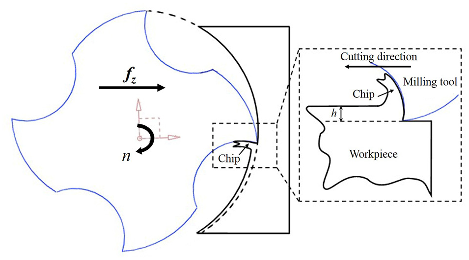
Schematic diagram of milling process and the relationship between milling process and orthogonal machining process.
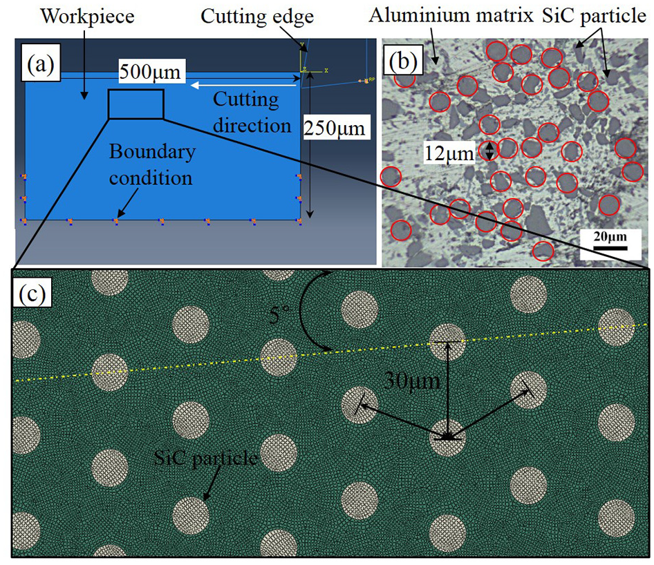
Schematic representation and mesh element of established model for machining SiCp/Al composites: (a) simulation model, (b) corresponding microstructure of SiCp/Al composite, and (c) particle distribution in the matrix.
The interaction between cutter edge and node points of cutting zone was defined as the surface-to-surface contact model with penalty contact algorithm. The Coulomb friction model was adopted, the friction formulation of “penalty” was used to specify tangential friction behavior for the contact between the tool and workpiece, and the normal behavior was defined as frictionless hard contact in the contact properties to accommodate a case of pressure-overclosure. For the two-phase model, the Tie constraints were established to ensure the equal initial displacements at particle-matrix interface and transfer the stress, while the friction coefficient of tool/matrix contact and tool/particles contact was 0.15 and 0.1, respectively. 29 For understanding residual stress originated from inhomogeneous inelastic deformation during cutting process, the whole simulation process was developed with two distinct steps including steady-state machining step and conversion of boundary condition step, which could promote the release of transient stresses.
The cutting process was realized through shifting the cutting edge. The following boundary conditions were specified in a reference point (RP) defined to control the cutting edge’s movement. The RP moved along the z axis at speed V in step 1 and then shifted along the Y axis at a fixed rate in step 2. Besides, “Encaster” boundary condition (
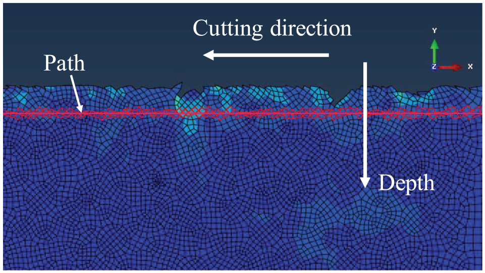
Measurement of residual stress distribution after machining.
Material properties and constitutive model
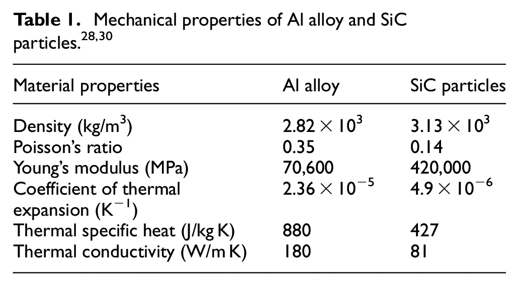
Aluminum alloy was developed as a deformable thermo-elastic-plastic material with quadrilateral continuum element and fracture criteria, and SiC particle was modeled as a brittle material. The detailed mechanical properties of SiC particle and Al alloy used for numerical simulation are shown in Table 1.
Material resistance to destruction is a function of the distortion intensity, distortion speed, and the temperature of distorted material.
33
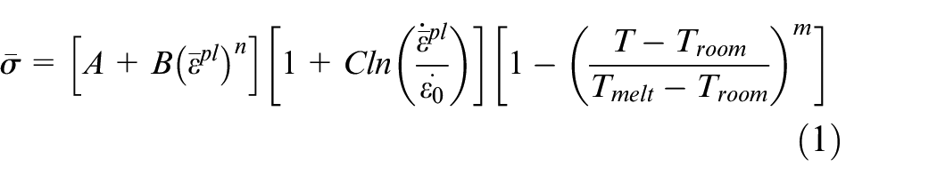
The Johnson-Cook (J-C) constitutive model, one of the most commonly used ones for predicting flow stress within metallic materials subjected to high strain, strain rate, and temperature, was applied to describe the dependency of stresses and deformations of Al matrix during machining process. Strain harden, strain rate effects, and thermal softening were combined in the J-C model, and the standard formulation of the stress-strain dependency for J-C model materials is shown in Figure 4. The relationship of stress-strain in elastic state was defined according to the Hooke’s law (
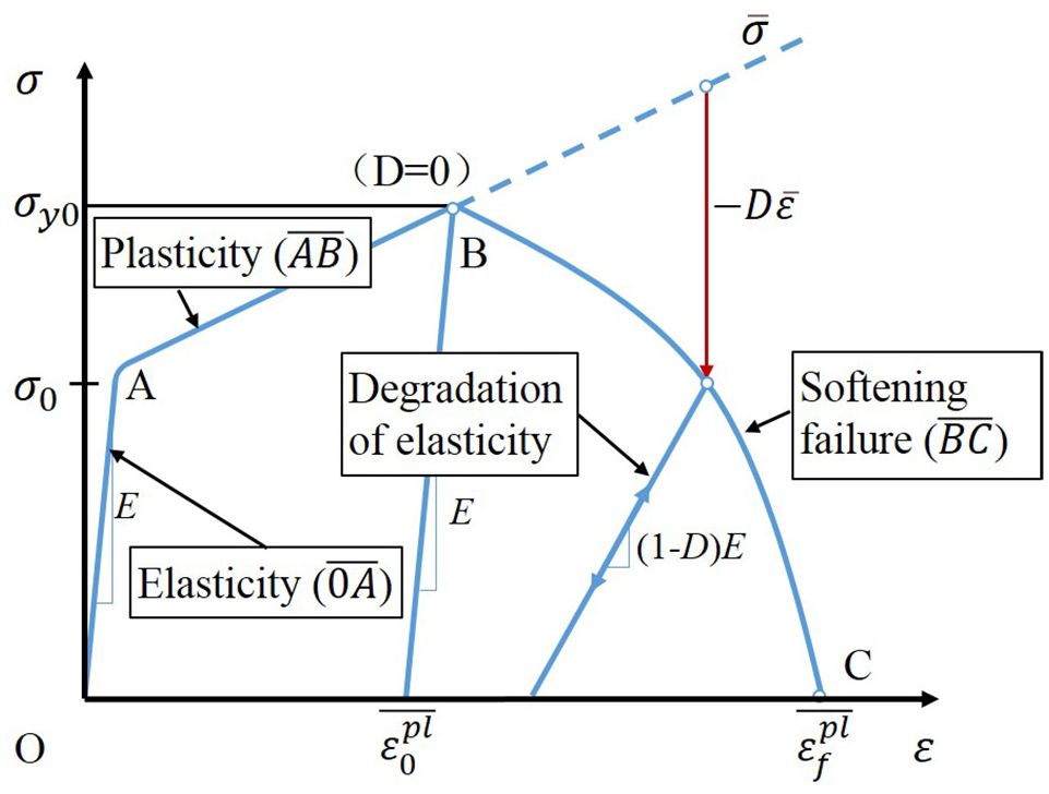
Stress-strain of Johnson-Cook constitutive model.
where
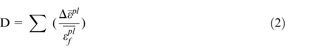

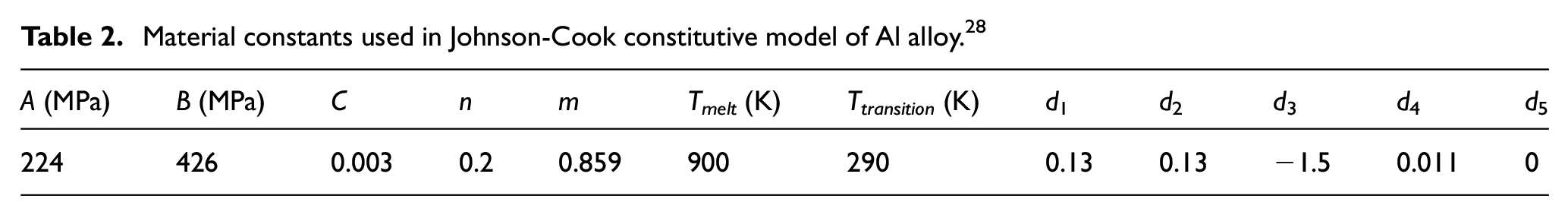
where d1–d5 are fracture parameters obtained from experimental trials, η is the stress triaxiality,
Material constants used in Johnson-Cook constitutive model of Al alloy. 28
SiC particles were in elastic state before fracture, and the relationship of stress-strain was defined according to the Hooke’s law. Therefore, the fracture failure occurred when the maximum stress satisfied the maximum normal stress criterion:

The failure evolution behavior of SiC particles was controlled by fracture energy criterion. According to the references,28,31 the maximum stress is 3900 MPa, the fracture energy
Experimental setup
All milling trials were conducted on a DMU 80T five-axis vertical machining center. A flat solid tungsten carbide four fluted end milling cutter with 6.35 mm diameter was used for the milling tests. The tool rake angle was 10° and the clearance angle was 6°. The force dynamometer (Spike_mobile) was mounted on the tool shank of machining center to record three mutually orthogonal cutting forces. Workpiece materials were fixed in the fixture on working table. The details of machining conditions are summarized in Table 3. Totally nine trials were carried out in accordance with various cutting speed and feed per tooth, and new tool was employed for each test, with detailed setup presented in Figure 5.
Detailed processing parameters selected for the experiment with fixed and variable values.
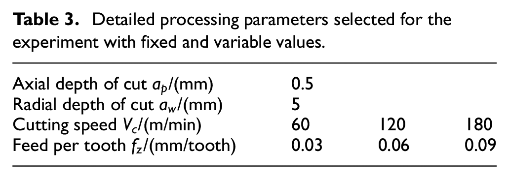
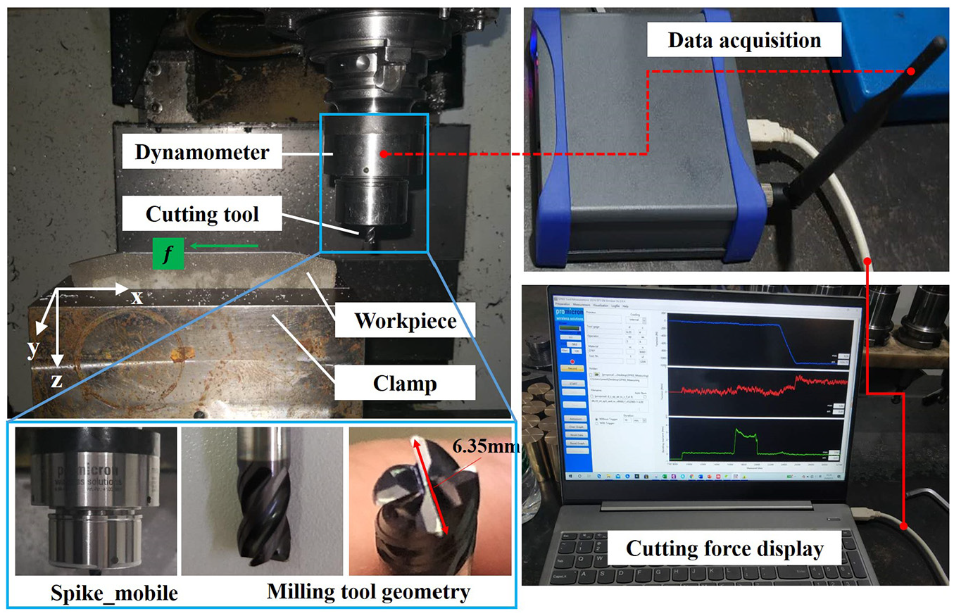
Experimental setup for milling trials.
The average surface roughness
Results and discussion
Chip formation and tool-particle interaction
Distribution of ceramic particles/reinforcement in metal matrix significantly modified the chip formation mechanisms, which were analyzed in this work in terms of cutting mechanism, stress/strain distribution and chip morphology. Figure 6 shows schematic of the three main deformation zones (I–III) in details, together with corresponding simulation results of stress field distributed in the cutting zone from the beginning of workpiece contacting with cutting edge. Take the simulation result under cutting condition with cutting speed of 60 m/min and uncut thickness of 0.03 mm as an example, when the cutting edge firstly engaged with workpiece (
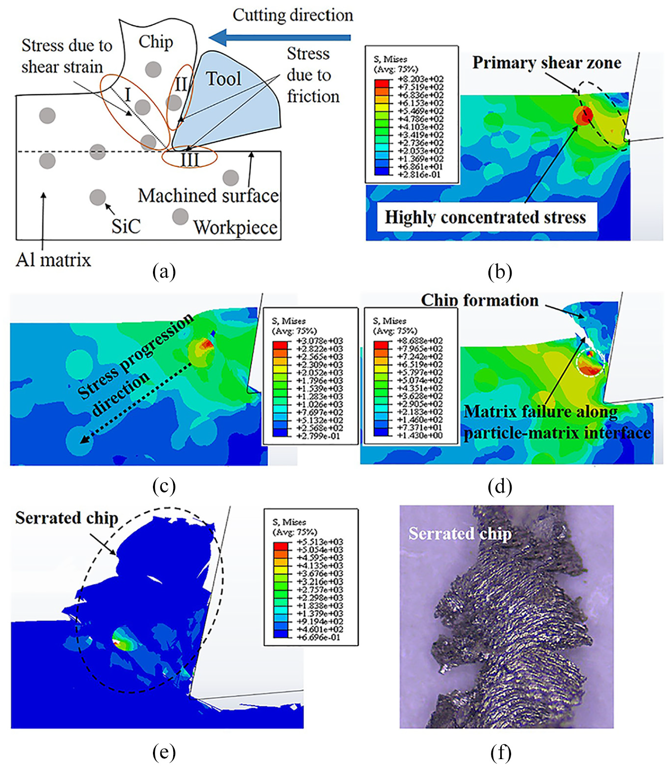
(a) Schematic showing the tool-chip interface, (b–e) different formation processes of generating serrated chips under cutting speed of 60 m/min and uncut thickness of 0.03 mm, and (f) chip morphology from experiment.
For the continuous cutting, the ceramic particles restricted the propagation of plastic stress, leading to an irregular stress distribution around each particle, as shown in Figure 6(c) (
Several relative positions (Figure 7(a)) between reinforcing particles and cutting edge resulted in different failure behaviors of reinforcement particles during milling SiCp/Al composites, including pull-out, crushing, cut-through, and push-in phenomena (Figure 7(b)–g). As for position “I” and “II,” the brittle fracture was not found (Figure 7(b) and (c)), which was probably due to the fact that the stress on the particles did not reach the brittle fracture criterion. Besides, the failure of particles was mainly manifested in pull-out phenomenon in this condition. It was observed in Figure 7(b) that the particles were embedded within serrated chips and slid along the rake face of cutting edge to separate from the workpiece. A localized maximum stress existed at tool-particle contact region near the first deformation zone (I). As shown in Figure 7(c), the particle in position “II” was most likely to be pulled out due to the fact that the strength of matrix was much lower than the SiC particles, leaving small cavity on the machined surface.
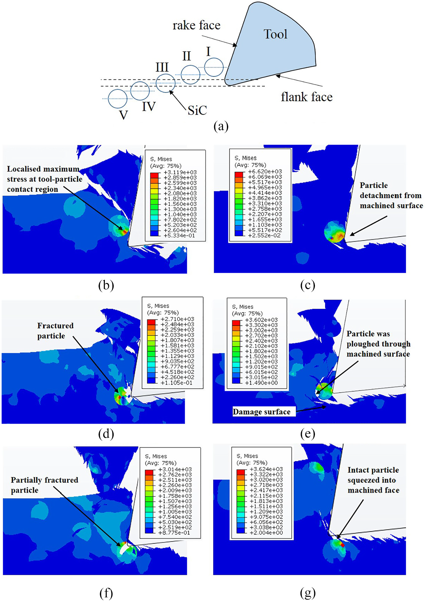
(a) Schematic showing different positions of SiC particles relative to the tool and (b–g) various tool-particle interaction behaviors in machining SiCp/Al composites.
In terms of positions “III,” the SiC particle might crack as the principal stress was greater than the tensile strength and the brittle fracture criterion was satisfied (Figure 7(d)). The cracks firstly appeared at the two points where the particle and matrix intersected along the cutting direction, in which the stresses showed maximum values. Ultimately, the particle was observed to experience fracture, and remnants were partially embedded in the newly formed/cut surface, which was possibly the main reason for producing worse surface morphology. Additionally, the particles might be also pulled out directly and plowed grooves on the machined surface when the thrust force was greater than the binding force between the particles and matrix, see the details in Figure 7(e). Thus, severe cavities and high level of residual stresses were generated because of debonding between matrix and particles.
With regarded to position “IV” in Figure 7(a), part of the particles was cut off caused by the fact that the principal stress exceeded the brittle fracture criterion, and some remnants were gradually pressed into the matrix with its plastic deformation (Figure 7(f)). Ceramic particles under the tool cutting path (position “V”) were pushed by the tool flank into the matrix (Figure 7(g)). It could be described by the reason that the particle was located in the III deformation zones, in which the materials were affected by the extrusion friction of flank face. To sum up, the failures model of particles below cutting path showed mainly partial brittle fracture and the remaining ones were pressed into machined face by tool flank face.
Surface morphology
The machined surface deterioration during milling SiCp/Al composites was mainly attributed to surface damage including cavities, scratches, and fractured particles within Al alloy. 34 The typical simulated morphology of machined surface for SiCp/Al composites is presented in Figure 8. The aforementioned surface defects found from simulation model could be clearly identified in experimental works, including the removal of matrix, pullout, and fractured SiC particles. Obviously, Al matrix was cut in ductile regime generating relatively smooth surface. Nevertheless, a few cavities caused by ceramic particle pull-out and fracture were found on machining surface. As aforementioned, the relative location between particle and cutting edge caused a remarkable effect on surface morphology. Some small cavities were generated when ceramic particles were directly cut off as their particle debris still adhered/embedded with matrix. Moreover, surface quality was closely related to the interfacial bonding strength between reinforcement particles and aluminum alloy. A large cavity formed on the machined surface, mainly due to the fact that SiC particles and matrix were totally removed in case of a strong interfacial bonding. Otherwise, the pull-out of hard SiC particle left behind a small cavity on machining surface. SEM micrographs in Figure 9 intuitively exhibited various surface defects. Plowed furrow and micro-scratches could be observed, which were formed under the following two main conditions. Firstly, the fragmented particles were squeezed by cutting edge/flank face and acted as sharp cutting edge to plow over the machined surface. Secondly, the hard particles might be pushed forward by cutter edge before pulled out, leading to plastic deformation of the matrix and plowed grooves. 19
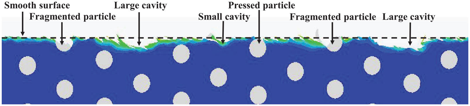
Simulated surface morphology from machining SiCp/Al composites.
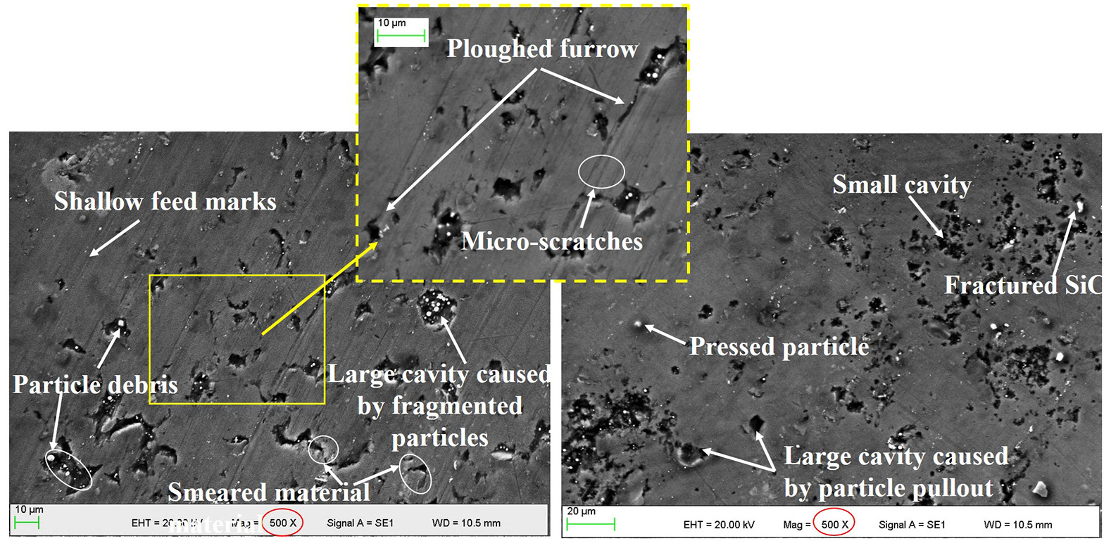
Micrographs showing typical surface morphology following milling SiCp/Al composites with: (a) feed marks and cavities and (b) fractured SiC particle and cavities.
Corresponding SEM micrographs of the finishing surface cross-sections are detailed in Figure 10. It was interesting to see that both ceramic particles contacting with cutter edge and the ones extending certain depth under machining surface were fractured, which mainly resulted from the squeezing of flank face. The thickness of defect layer with broken-SiC particles increased from 25 to 34 µm with feed per tooth increasing from 0.06 to 0.09 mm/tooth. This phenomenon could be attributed to the fact that the variation of uncut chip thickness probably changed the force of reinforcement particles in the subsurface layer, as the detailed results of force levels showing in Figure 11. The average lateral force was processed and the value was calculated by
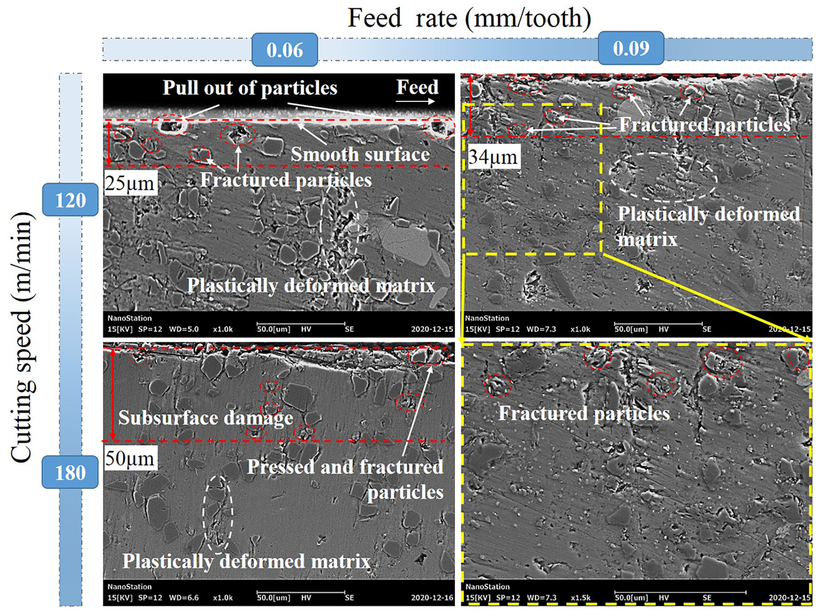
SEM micrographs showing cross-sections of machined surfaces following milling SiCp/Al composites with different cutting parameters.
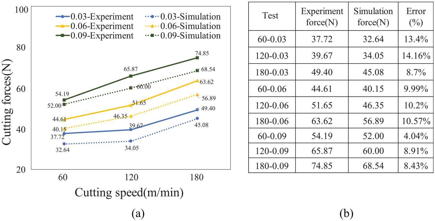
(a) Experimental and simulated cutting forces under different cutting conditions when milling SiCp/Al composites and (b) the errors between experiment force and simulation force.
Typical surface morphology under different cutting parameters was also studied to further evaluate failure mechanisms, with details shown in Figure 12. By comparing Figure 12(a) and (b), it was very interesting to find that a large number of cavities were formed under higher cutting speed (180 m/min), which indicated that the SiC particles possessed a higher tendency to be pulled out under higher cutting speed than lower one (60 m/min). This phenomenon was mainly because cutting temperature increased rapidly under higher cutting speed. 35 The workpiece underwent relatively high temperature in dry machining throughout the whole cutting process, thus the particles were easily pulled out to form cavities with softening of Al matrix. By compassion of Figure 12(c) and (d), it was seen that more pits were found on the machined surface in case of higher feed per tooth (0.09 mm/tooth), resulting in poor surface integrity. These observations confirmed the results of surface roughness analysis discussed as follows. Chips generated with higher feed per tooth were relatively thick enough to entrain ceramic particles and then increased the tendency of particle pullout to some extent. Some shallow pits could be observed on the machined surface (Figure 12(d)). In contrast, smaller uncut chip thickness presented the higher tendency of fractured particles, leaving partially fine particle debris in the matrix to fill the pit (Figure 12(c)). Meanwhile, highly deformed aluminum matrix could also fill or cover the small pits on the machining surface. Therefore superior machining surface integrity was obtained under the lower feed per tooth (0.03 mm/tooth).
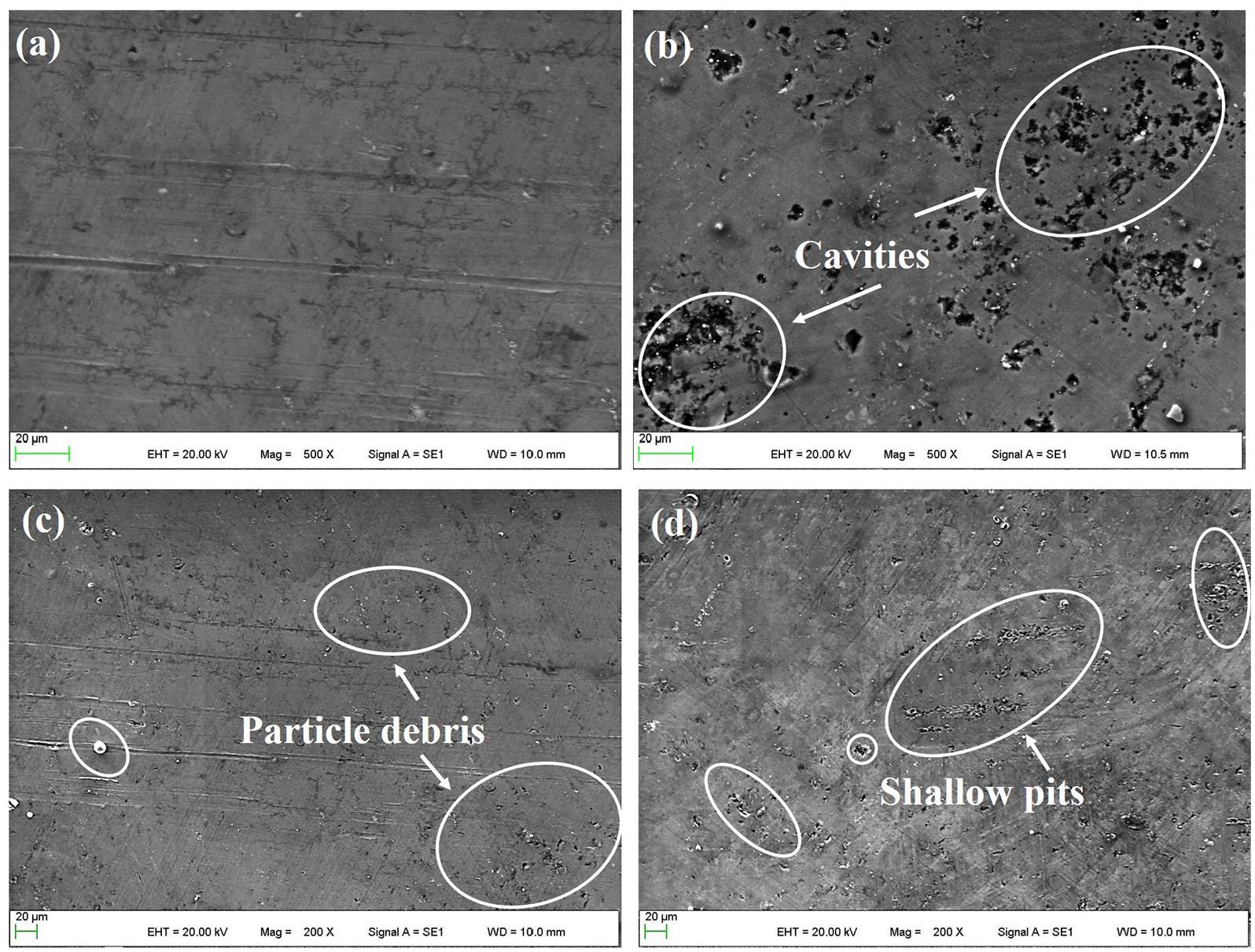
SEM micrographs showing typical surface morphology following milling SiCp/Al composites with different cutting parameters: (a) 60 m/min and 0.03 mm/tooth, (b) 180 m/min and 0.03 mm/tooth, (c) 60 m/min and 0.03 mm/tooth, and (d) 60 m/min and 0.09 mm/tooth.
The effects of cutting speed and feed per tooth on surface roughness is detailed in Figure 13. It was obvious that surface roughness (Ra) increased with both cutting speed and feed per tooth, which was in agree with the above-mentioned SEM micrographs. Specifically, as the feed per tooth increased from 0.03 to 0.09 mm/tooth, surface roughness increased up to 75%. Moreover, the increment reached ∼125% when cutting speed increased from 60 to 180 m/min. Previous work confirmed that relatively high machining temperature was generated at high cutting speed, leading to improved plasticity of aluminum matrix. 21 SiC particles were easily separated from the matrix, thereby leading to large cavities on the machined surface. Furthermore, pulled particles and partially softened matrix material were swept and moved across the machined surface, resulting in some scratches. All these factors led to an increase in surface roughness and similar conclusion was also reported by Yang et al. 36 The height of crest in surface profile caused by side flow on feeding mark ridges under higher feed per tooth would increase because of high ductility of Al matrix. Furthermore, relatively higher cutting force resulted in severe deformation of workpiece and deteriorated surface quality, which was in line with corresponding SEM analysis in Figure 12.
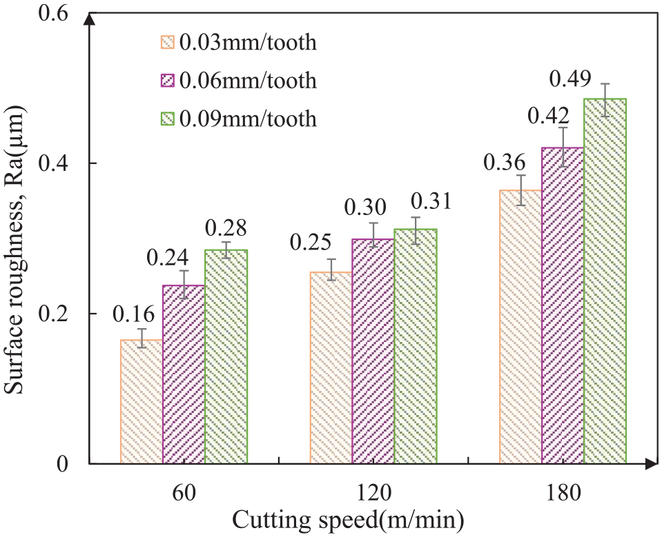
Influence of cutting speed and feed per tooth on surface roughness following milling SiCp/Al composites.
Residual stress
The measured residual stress on machining surface under different machining parameters is shown in Figure 14, which was generally compressive under all the cutting conditions in this work when dry milling SiCp/Al composites and was in good agreement with the previous related literature. 22 This phenomenon could be attributed to the fact that residual stress generated by the mechanical action was dominant over the thermal effect for the MMCs. Mechanical interaction in the cutting zone resulted in compressive residual stress, while the thermal effect produced via friction led to tensile residual stresses. There were three main factors including the limitation of Al materials flow with the addition of particles, the indentation of particles and extensive compression of Al materials between reinforcement and milling cutter, which caused severe mechanical deformation taking over thermal effects, 22 resulting in compressive residual stress on machining surface of Al/SiC composites. Moreover, there was higher tool-particle interaction at relatively low feed per tooth and thus the three mentioned factors became relatively prominent, which contributed to the results that the magnitude of compressive residual stress reached the maximum level (36.4 MPa) among the three ones when the feed per tooth was 0.03 mm/tooth.
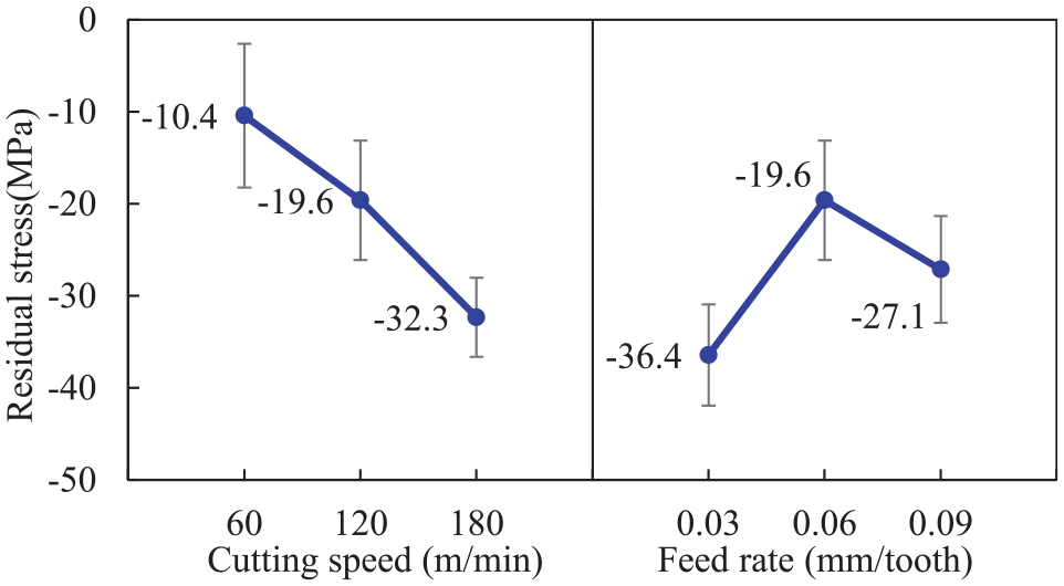
Effect of cutting parameters on surface residual stress following milling SiCp/Al composites.
Simulated residual stress profiles following milling SiCp/Al composites are detailed in Figure 15. The simulated surface residual stresses (depth = 0) were qualitatively consistent with the experimental results (Figure 14). The magnitude of compressive residual stress showed an increasing trend with higher penetration depth in a certain range, and the maximum compressive residual stress appeared at the depth of ∼20
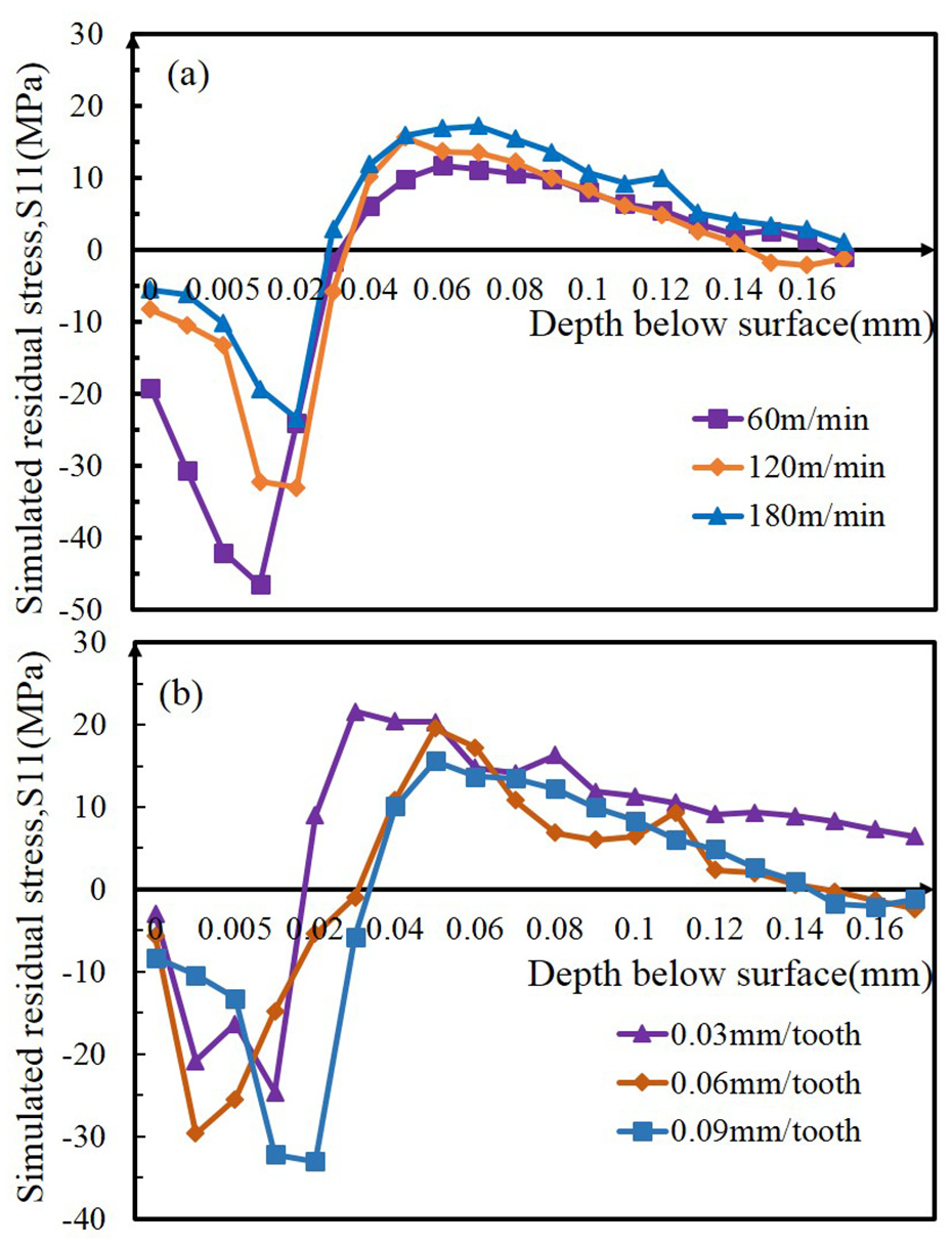
Simulated residual stress profiles following milling SiCp/Al composites with variation of: (a) cutting speed and (b) feed per tooth.
As mentioned above, the simulated compressive residual stress was in reasonable qualitative agreement with experimentally recorded values, which verified the rationality and validity of the present simulation model. According to the findings from Wang et al., 23 if recorded stress was less than 100 MPa, experimental values might have notable error, thus the residual stress results were suggested for qualitative analysis considering the value accuracy using X-ray diffraction. According to the results in Figure 15(a), the magnitude of maximal compressive residual stress presented a trend to decrease with the increase of cutting speed. As high milling speed generally produced relatively higher temperature, the effect of temperature was comparatively limited under low cutting speed. The depth of compressive residual stress penetration layer varied with feed per tooth (Figure 15(b)), which was mainly attributed to the fact that the higher cutting force was induced by larger removal rate under higher uncut chip thickness.
Burr formation
Burr generation is a very complex material deformation process, as several factors including workpiece material characteristics, cutting parameters, tool geometry, tool wear, and the use of coolant directly affect burr morphology. The primary shear zone, plastic deformation zone, and elastic deformation zone were produced within the workpiece during machining, with the schematic detailed in Figure 16. When the yield strength of workpiece was less than the high contact stress, Al matrix primarily flows along the upward direction and then forms chips. 38 The formation of burrs at cutting end was similar to the generation process of chips. The deformation and stress distribution changed when milling cutter was close to workpiece exit edge. The plastic deformation zone was extended toward the edge of workpiece. 39 These permanent plastic deformations formed preferentially in the direction of lowest resistance. Therefore, a large catastrophic deformation occurred at the workpiece edge and a negative shear zone developed in this stage. As the tool further moved toward the edges of workpiece, cracks initiated and grew along the primary shear zone. The exit side was not strong enough to support thrust force, and partially deformed chips bent along cutting direction at the end of machining to form burrs, which could be mainly divided into the Poisson burr, rollover burr, and tear burr according to different formation mechanisms. 39
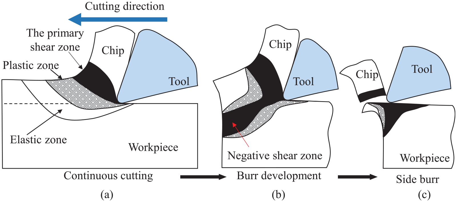
Schematic showing burr formation process during machining composites including: (a) continuous cutting, (b) burr development, and (c) side burr formation.
Burr morphology with different cutting parameters is shown in Figure 17. The sample in this work was processed by end-milling with 5.0 mm radial depth of cut, while the diameter of milling tool was 6.35 mm. Consequently, limited tear burr was observed, which formed in material tearing loose from the workpiece rather than shearing effect. 39 It was clearly found that the burr size from up milling side was generally much smaller than the one from down milling side caused by cut in or cut out, which was in line with previous findings. 40 On the up milling side, the cutter teeth cut in the workpiece and a small amount of Poisson burrs were produced, which were formed by the material’s bulge to the sides when they were compressed until permanent plastic deformation occurred. 39 Consequently, the analysis of burr formation in this work only concentrated upon that from down milling side. The main type of burrs in down milling was rollover burr, which was essentially a bent chip. 39 With relatively low cutting speeds (60 and 120 m/min), it was observed that the main type of burrs was the smaller rollover burr under 0.03 and 0.06 mm/tooth, while burr morphology gradually changed to the larger rollover burr together with slight Poisson burr when the feed per tooth reached 0.09 mm/tooth. This phenomenon was illustrated by the fact that severe plowing phenomenon occurred under larger feed per tooth. Furthermore, it was also found that the rollover burr under the cutting speed of 180 m/min was significantly larger than that under the cutting speed of 60 and 120 m/min. The critical reason was that higher cutting temperature produced at high cutting speed, leading to the softening of aluminum matrix, which thus advanced the plasticity of SiCp/Al composites. Some materials that could not be removed in the form of chips were pushed to the edges, large rollover burrs were subsequently formed with continuous accumulation.
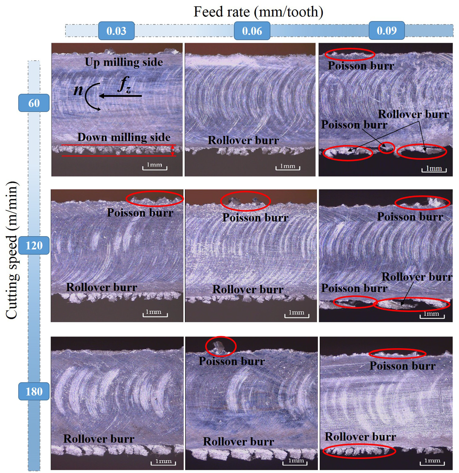
Burr morphology under different cutting parameters following milling SiCp/Al composites.
The effects of cutting speed and feed per tooth on burr width is shown in Figure 18. When increasing cutting speed from 60 to 180 m/min, burr width of the down-milling side increased from 444 to 740
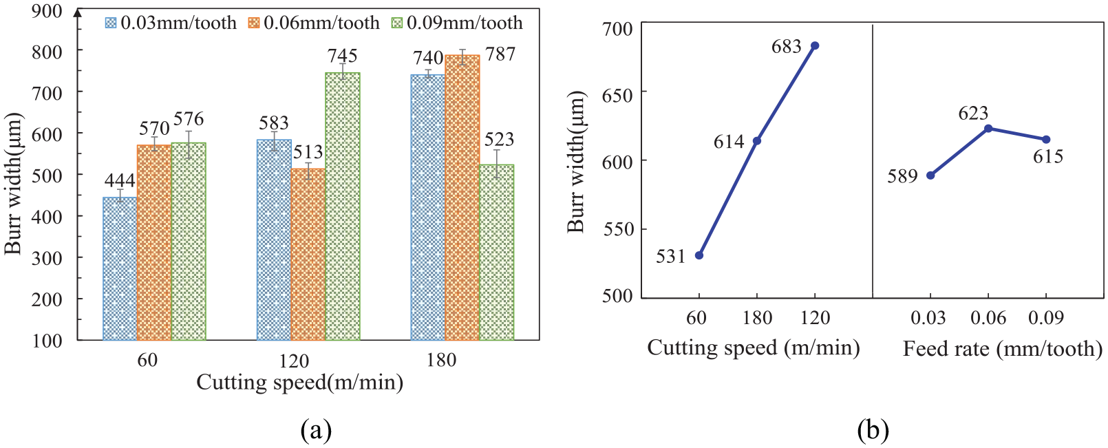
(a) Variations of burr width with different cutting parameters and (b) main effects plot for the analysis of burr size.
Conclusions
This work proposed a two-phase finite element model using commercially available software ABAQUS/Explicit and investigated the detailed cutting mechanisms and surface integrity via analyzing cutting edge-particle interaction, surface morphology and roughness, subsurface damage and residual stress distribution, as well as burr formation following simulation and experimental trials when milling SiCp/Al composites. Especially, the distribution of residual stress along the depth direction were predicted by the finite element model. The maximum error value was less than 15% between experimental and simulating cutting force, verifying the validation of the model. The following conclusions could be drawn from above comprehensive analysis.
(1) The simultaneous action of plastic shear deformation of Al alloy and fracture along the particle-matrix interface ensured the continuous formation of serrated chips. The different relative positions between milling cutter and reinforcement generated various particle removal modes including crushing, cut-through and pull-out, which were the main factors affecting the formation of different surface morphology.
(2) Surface defects including cavities, scratch marks, fractured particles, and debris embedded within matrix were observed from simulation and experimental trials. The thickness of broken-SiC particle layer in subsurface deepened with higher cutting speed and feed per tooth, especially when cutting speed increased from 120 to 180 m/min, the thickness increased from 25 to 50 μm.
(3) Compressive residual stress was generally concentrated on machined surface as mechanical effect was dominant over the thermal effect, while tensile residual stress appeared with higher depth under machined surface. The compressive residual stress showed an ascending trend with the increase of depth, and the maximum value was obtained at ∼20 μm depth when using 0.03 mm/tooth feed per tooth.
(4) The burr size from up milling side was much smaller than the one from down milling side. A small amount of small Poisson burrs were induced on the up milling side, while the main type of burrs in down milling was the rollover burr. Burr width increased up to 28.6% when increasing cutting speed from 60 to 180 m/min.
Footnotes
Appendix
Authors’ contributions
M Li: conceptualization, investigation, funding acquisition, writing-original draft and editing; Z Wang: methodology, data collection, writing-original draft; W Li: data collection, writing-reviewing; X Yang: writing-reviewing and editing.
Declaration of conflicting interests
The author(s) declared no potential conflicts of interest with respect to the research, authorship, and/or publication of this article.
Funding
The author(s) disclosed receipt of the following financial support for the research, authorship, and/or publication of this article: This work is supported by the National Natural Science Foundation of China (51905163) and Natural Science Foundation of Hunan Province (2019JJ50053).