
Abstract
The grinding process is often maligned by grinding burn; which refers to many unwanted effects, including residual stress formation. This paper presents an overview of the role of grinding wheel technologies in the surface response and residual stress formation of thin section Inconel 718. Using production standard equipment, conventional abrasive vitrified, and super abrasive electroplated wheel technologies were evaluated in initial comparative trials. Results revealed the dominant residual stress profiles, which manifested as measurable distortion and the thermo-mechanical impact of grinding, such as softening. Following this, a parametric study was carried out using cubic boron nitride super abrasive electroplated wheels to investigate the interaction of grinding parameters on the generated output. It was shown that at increased grinding aggressions, tensile stress regimes increased resulting in increased distortion magnitudes. The study highlights the importance of assessing residual stress formation when manipulating both wheel technologies and grinding parameters. It is envisaged that with additional assessment, a route to an engineered residual stress profile might be achieved.
Introduction
Grinding processes are prevalent in the manufacture of aero engine components for high temperature applications where tolerances and features demand such processes. 1 Techniques are moving beyond those typically deployed in the aerospace sector on turbine blade datum features to alternative processes such as point grinding, super abrasive machining and turn-grinding for applications on new commodities such as blade root mounting slots, impellers and blisks.1–3 With this comes new technical challenges but also increasing production volumes leading to a demand for process optimisation and efficiency. Allwood et al. 4 discussed the opportunities for increasing manufacturing rates in grinding. Control of the energy partition was cited as being critical to ensure workpiece process output metrics are managed. It was concluded that the rate at which grinding could be increased was dependent on the ability to cool the process. In addition, the specific interaction between a selected wheel system and workpiece material dictates wheel conditioning / wear mechanisms and subsequent dressing intervals. To achieve the effective development of a high performance grinding process, optimisation of process interactions is required to increase the knowledge base and ensure output metrics are understood. 5 In such scenarios, grinding practitioners will typically seek process optimisation through variations in wheel selection and parameters. The interaction of input variables on key output metrics, especially in the case of nickel based super alloys, is not widely reported. This is critical especially in applications that operate in safety critical conditions or have geometries that are sensitive to process interactions such as distortion.
The generation of residual stresses in grinding processes have been identified to occur through thermal expansion and contraction during grinding, phase transformations due to high grinding temperatures or plastic deformation attributed to the material removal by the abrasive grains of the grinding wheel. 6 Furthermore, thermal expansion and contraction has been identified as a major source of residual stress generation. It is believed that the problem of controlling residual stress formation is a problem of controlling grinding temperature. 6 The rise in temperature of the material is mainly dependent upon the energy partition of the system. 7 Up to 85% of the energy generated has been reported to be transferred into the workpiece when grinding Inconel 718 with conventional abrasives. 8 Theoretical studies have looked at approaches to utilise this phenomenon with additional heat sources to mitigate tensile stress generation 9 and develop compressive stress states. 10 The challenge in grinding processes is further exacerbated due to the multistage nature of material removal strategies.11,12 Kohls et al. 11 presented a concept of Process Signatures which looked to correlate inherited residual stress conditions and the interactions with multi stage grinding processes. They also developed a combined laser deep rolling process to independently control mechanical and thermal loads as an analogy to grinding process mechanisms. The progressive development of compressive residual stress was reported by Borchers et al. 12 throughout a multistage grinding processes using a mobile XRD technique. Such techniques and knowledge base is critical to progressing engineered surface conditions. Klocke et al. 5 reported that one of the many metrics of a high performance grinding process relates to the ability to influence workpiece properties (for example residual stress) through parameter manipulation for functional performance benefits.
Compressive stresses are generally encountered in low temperature grinding operations and generated by mechanical interactions of the process. 13 These interactions occur where the abrasive grains produce a permanent plastic deformation of the surface material and an elastic deformation of the adjacent sub surface regions. 6 Tensile stress regimes are generated when the thermal stress in the material exceeds the material yield stress, or that deformation is thermally induced rather than mechanically.6,13 During the grinding operation, a thermal gradient is generated between the high temperature surface material and lower temperature bulk material. If the thermal expansion of the high temperature surface material is constrained by the low temperature bulk material, then a tensile stress regime can be avoided. 6 However, the magnitude of the thermal stress is based upon the energy input, the thermal conductivity of the elements within the system and the elastic modulus of the material. Should the thermal stress exceed the yield stress, a permanent deformation can occur in the surface material. 6 Subsequently, as the plastically deformed high temperature surface material and the cooler bulk material return to ambient conditions, a residual tensile stress forms in the surface material. 6
The lower grinding temperatures found with cubic boron nitride (cBN) super abrasives, as opposed to aluminium oxide (Al2O3), are based on its higher thermal conductivity allowing improved heat removal from the work material and a maintained level of abrasive sharpness reducing frictional heating.8,14,15 As such, cBN grinding has generally been reported to result in a compressive residual stress regime being generated in the surface regions of the material. 16 The mechanical impact can be observed at low radial engagements, through the burnishing effect, but also where lower grinding forces are found, increasing the magnitude of compressive stresses.15,17 Work carried out by Quan et al. 18 when machining GH4169 (a material similar to Inconel 718) identified compressive residual stress conditions when grinding with electroplated cBN grinding wheels to a magnitude and depth to bulk of −765 MPa and 200 µm respectively.
Utilising a conventional abrasive wheel type revealed the importance of coolant; whereby its absence produced the largest tensile stresses in the study by Ulutan et al. 14 Studies also revealed the primary strengthening phase, γ’, had been dissolved to a depth of 800 μm, giving rise to softening, micro cracking in the grinding direction and crack formation along grain boundaries.13,14,19 When grinding GH4169 with Al2O3 abrasives Zeng et al. 20 reported a swing from compressive to tensile dominant stress states when comparing external cylindrical grinding and plain surface grinding modes respectively. Yao et al. 21 reported on an improvement to the magnitude and depth of tensile residual stress when grinding Inconel 718 through transition from a resin bonded cBN grinding wheel to a conventional vitrified Al2O3 grinding wheel when surface grinding. This required a manipulation of grinding parameters, primarily depth of cut, which effected both chip formation mechanisms and the temperatures generated.
The interaction between surface integrity metrics and resultant component fatigue performance has been reported by several authors.18,22 Novovic et al. 22 reported that a complex relationship exists between fatigue life and workpiece microstructure, surface topography and surface integrity. However, it is generally concluded that fatigue life is benefited from compressive residual stress regimes, but that surface roughness can temper the effect. Process interactions should also be carefully considered, which are typical in complex aerospace components, Quan et al. 18 demonstrated that processes such as polishing can have a significant impact on fatigue performance of components with changes to surface integrity and residual stress from inherited pre-machining activities.
This paper aims to provide an overview of the residual stress and surface integrity response of Inconel 718 to grinding wheel technologies. Additionally, the residual stress response when grinding with cBN wheels, was evaluated further as it has been reported that they are preferred for grinding applications where thermal damage of the work piece is a problem. 7 Within literature, there is a gap in trying to relate key process variables to specific output metrics such as residual stress profile generation and the resulting impact on workpiece distortion. It is hypothesised that if the resulting residual stress profile can be engineered through parameter manipulation then in tandem with a modelling approach, processes could be optimised within functional and geometrical constraints in a virtual environment.
Experimental work
The experimental approach within this study has been split into two phases, as summarised in Figure 1. Phase 1 trials were targeted at investigating the effect of wheel technology on the resultant residual stress state and surface integrity. Whilst the grinding wheel was treated as the primary variable, tests were developed to be accommodating to specific benefits of each specific technology and their typical operating conditions. To ensure a level of consistency when testing, parameters were adjusted to yield a consistent mechanical aggression which will be detailed later. Within Phase 2, a single wheel technology type was selected based on observations from within Phase 1 and those reported in literature. During this final phase, key process variable interactions were investigating to establish a methodology for controlling resultant residual stress state and hence optimising the distortion generated.
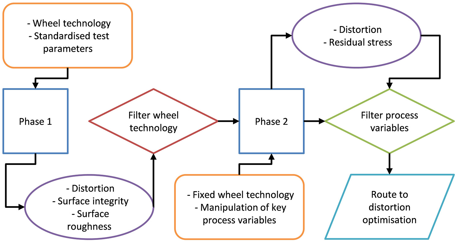
Flow of experimental activity.
The material selected for this investigation was Inconel 718 (ASTM B637). Sheet stock in a nominal thickness of 1.6 mm was used to produce samples for machining trials. Samples were to the geometry of Almen strips which are used in shot peening intensity analysis enabling stress assessment via both destructive and non-destructive methods. It was further reflective of thin section grind scenarios frequently seen in aero engine applications. Material was annealed and pickled and underwent subsequent solution treatment and ageing heat treatment in sheet geometries of 210 mm × 300 mm. Samples were further sectioned using WEDM to an individual coupon geometry of 19 mm × 75 mm.
Trials were conducted on a Mori-Seiki NT4250 DCG Mill-Turn platform equipped with grinding capability, see Figure 2. Grinding wheel dressing and numerically controlled coolant delivery was achieved using the machine tools lower turret driven tooling stations. With multiple tooling positions on the lower turret, coolant nozzles and dressing arrangements were automated within the test process. Grinding wheels were loaded to the tool spindle and the fixture and test coupon arrangement was loaded to the workpiece spindle via a chuck assembly.
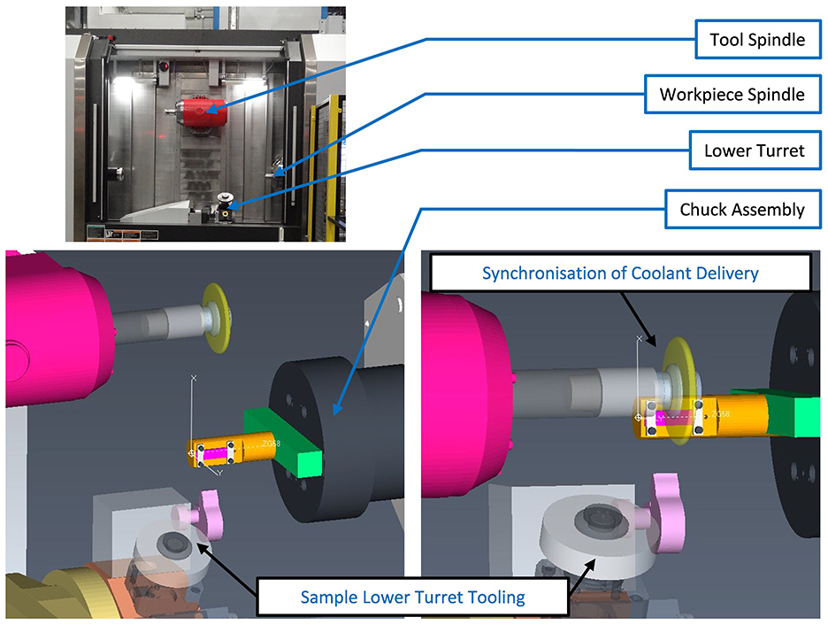
Extant view of machine tool and experimental arrangement.
The fixture was a simplified arrangement machined from a general engineering steel and finish ground in-situ. Two coupon clamps using four off M6 bolts tightened to 6 Nm were used to secure and locate the test coupon. In all tests, a down grinding mode was utilised with the tool spindle in a horizontal orientation. On each coupon, a designated grinding area was removed to the target radial test depth utilising multiple cross feed grinding wheel passes defined by the specific test regime.
Coolant was delivered to the grinding process via a coherent jet nozzle arrangement mounted to a numerically controlled and driven tool holder. This allowed a level of synchronisation to be achieved between coolant nozzle and tool spindle motions maintaining key variables. Lower turret motion was restricted to two off linear axes and the driven tool holder enables manipulation of the coolant nozzle in a single rotary axis. The specific test arrangement is shown in Figure 3. The coolant delivery strategy was designed to approach delivery conditions approaching those of an established VIPER grinding process 1 which is widely deployed in aerospace grinding applications of nickel based super alloy materials. Such grinding processes typically deploy a combination of high-pressure coolant delivery for wheel scrubbing and coolant penetration into the grinding wheel. Flow rates are also typically significantly higher than the theoretical application capacity to ensure a sufficient safety factor is in place to mitigate thermal damage. Coolant pressure in this application was defined by the pump pressure (100 bar) yielding 100 l/min in nozzle output. The emulsion used was Houghtons Hocut 768 and was maintained within a control window (concentration of 6%–8% and temperature 20 ± 2°C). The window of control values reflects the industrial nature of the test equipment whereby nominal values were targeted within a defined set of control limits.
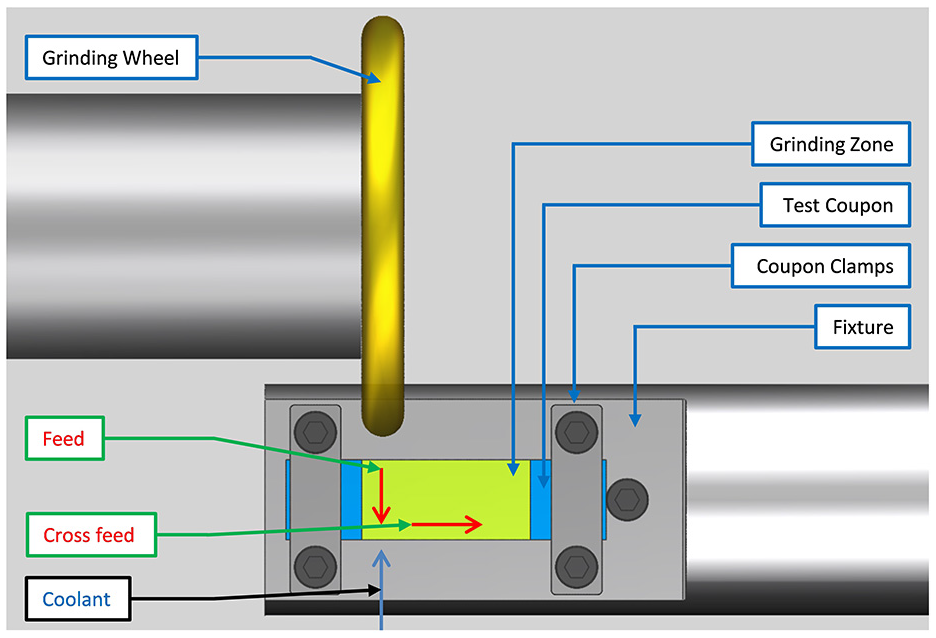
Schematic of the local experimental arrangement.
Resultant coupon geometry was assessed on a coordinate measurement machine. Assessment was made using three scans in the coupons longitudinal and transverse direction on the unground coupon surface before and after grinding trials to quantify flatness. Surface roughness of the ground surfaces were assessed in the feed and cross feed direction using a Mahr Stylus Profilometer (Perthometer). Measurements reported are the average of four surface profile measures in each direction using a sampling length (lr) of 0.8 mm and an evaluation length (ln) of 4.8 mm as per ISO4288-1998. Results are reported in terms of arithmetic mean roughness deviation (Ra) as this aligns with typical industrial criteria for surface roughness assessment.
Residual stress measurements were conducted using two techniques. Surface inspection was carried out using a Proto iXRD portable system with a 300 W x-ray generator, 30 mm focal length and 2θ range of 123° to 171°. On inspected samples, nine points were selected for analysis. The hole drilling method was deployed at Stresscraft Ltd using a miniature PC controlled 3-axis orbital drill allowing measurement to a depth of 320 μm at a single, central point on samples. Residual stresses were resolved in both the feed and cross feed direction. Residual stress in the condition of supply material was assessed to ensure that the planned material removal during the grinding trials was greater than the stress depth inherited from the heat treatment process. This was to ensure that the measured stress post trials was a function of the grinding process variables.
Surface integrity was assessed optically using a Leica Optical Microscope up to a maximum of 1500x with samples sectioned in both the feed and cross feed direction using a standard preparation, polishing and etching regime. Samples were sectioned using a diamond cut off disc, hot mounted in Bakelite, ground with silicon carbide (SiC) paper, polished with diamond grit and finished with 0.5 µm colloidal silica. After polishing the samples were etched in Kallings No. 2 for up to 20 seconds. Microhardness measurements were conducted using a Knoop indenter at a load of 0.025 kgf for 15 seconds on as polished samples in multiple locations.
Phase 1 experimental details
A total of eight wheel specifications of two primary variants were evaluated, conventional wheels having dressable bond systems and profiled single layer electroplated super abrasive wheels which within this context are deemed to be non dressable due to the bonding mechanism. Conventional wheels were dressed using a single point diamond tool (stationary profile diamond shape 50PD, Tyrolit 475960 with a 0.250 mm diamond radius) at a dressing depth of 25 μm per pass and an overlap ratio of 4. Grinding wheel speed during dressing was maintained at the target test cutting speed (vc), the feed rate during dressing was therefore adapted to maintain the specified overlap ratio and was adapted to reflect the active wheel diameter and subsequent rotational speed. Electroplated wheel variants were provided with the same profiled form (5 mm radii form on a 10 mm wide wheel) and underwent no wheel dressing or pre-test conditioning.
Coupons were ground in the targeted grinding zone (total cross feed direction of 40 mm) with each wheel and parameter set as defined in Table 1. With regards to grinding parameters and the dressable nature of selected wheels, a simplified chip thickness value, termed Aggression (Agg), 23 was maintained across tests to manage the change in wheel diameter expected. In the cross-feed direction, the incremental axial depth of cut was fixed across all trials and selected based on a resulting workpiece scallop height of 3.2 μm (ap 0.341 mm). The radial depth of cut was controlled between test coupons via on machine inspection to achieve a consistent radial depth (ae 0.8 mm) for each test. Test points were randomised and repeated, generating two test coupons.
Phase 1 wheel specifications and test variables.
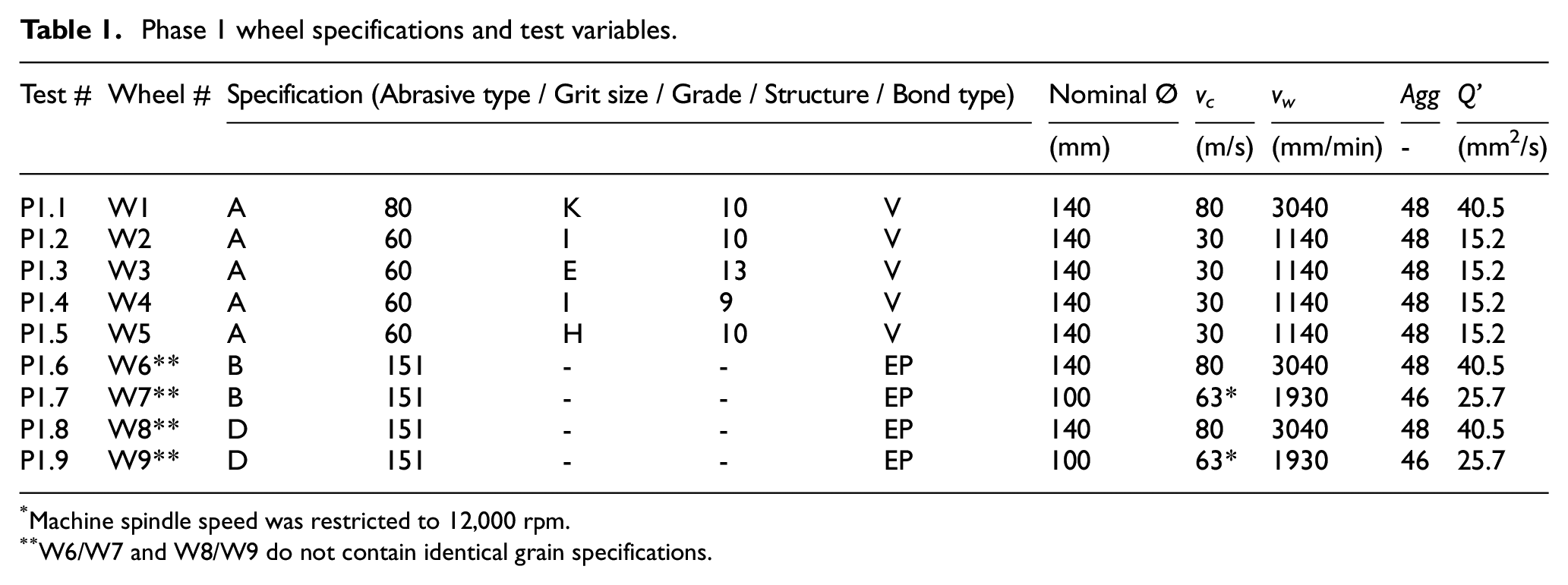
Machine spindle speed was restricted to 12,000 rpm.
W6/W7 and W8/W9 do not contain identical grain specifications.
Within Phase 1 testing, grinding wheel specifications for conventional vitrified wheels (W2 to W5) were selected to represent a range of typical VIPER specifications used in production environments. All of these specifications were tested under fixed cutting speed and aggression settings which resulted in fixed feed rates and material removal rates. With the specific grinding scenario under investigation (profile wheel form and surface scanning approach), alternative wheel technologies were applied to evaluate the effect of a variable approach. To ensure a fair assessment of the specific wheel technology, cutting speeds were aligned to wheel operating recommendations. For W1, the grain utilised was a 100% engineered ceramic alumina grain with recommended higher cutting speeds compared to the conventional alumina wheel systems. Similarly, the super abrasive specifications are known to have operating parameters in excess of conventional abrasives. As highlighted in Table 1, tests were ultimately restricted by spindle speed but to ensure a level of alignment, cutting speeds for W6 and W8 were matched to the aforementioned specification. The remaining two specifications (W7 and W9) were operated at a maximum achievable rotational speed and were therefore operated at a lower cutting speed due to a delta in wheel diameter. With specifications operating at recommended cutting speed conditions, the aggression parameter was selected to be consistent across all products in an attempt to operate the wheels under similar simplified chip load scenarios. It should be noted however, that aggression is a significant simplification of true chip thickness and does not account for grit size or distribution variations. In the same logic, wheel engagement (in terms of the two-axis arc of contact – wheel profile and wheel diameter) was maintained. This resulted in variations in both feed rate and material removal rate which is a function of the benefit of these alternative wheel specifications.
Phase 2 experimental details
Selected wheel specifications were taken forward for further evaluation (W6 and W7). The test format replicated those of Phase 1 trials but utilised the profiled single layer electroplated cBN super abrasive wheels only, with process variables as defined in Table 2. Within this phase, the motivation was to assess the impact of key process variables on the resulting residual stress profile generation and subsequent distortion. Cutting speeds were mostly maintained at optimum levels and the aggression term was used to drive variations in feed rate and depth of cut. Feed rate and depth of cut were manipulated to reflect different grinding modes (creep feed and high feed) as well as different material removal strategies / number of passes. Comparisons can be drawn between testing pairs, as denoted in column 1 in Table 2. A and D allow comparison of a semi-finishing and finishing scenario, B and E allow a comparison of high and low feed rates at fixed depths of cut and therefore increasing aggression, C and F allow comparison of depth of cut and cutting speed when compared to Phase 1 test points.
Phase 2 wheel specifications and test variables.
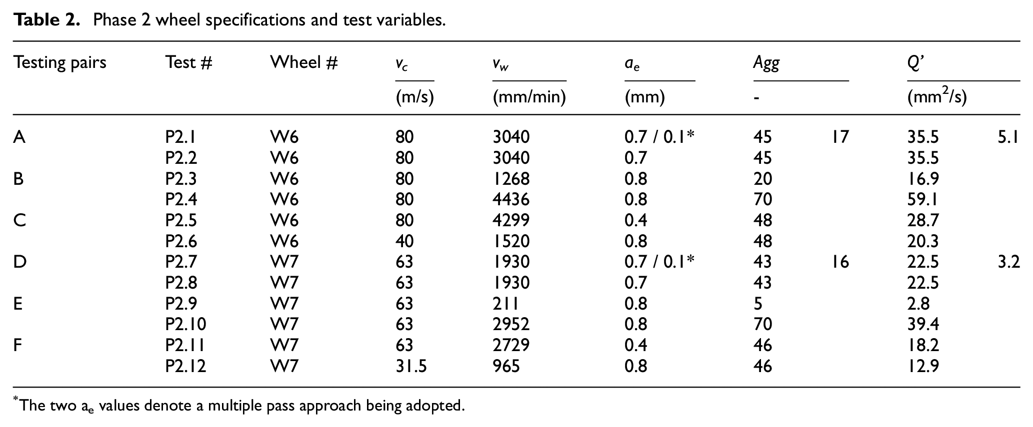
The two ae values denote a multiple pass approach being adopted.
Results and discussion
Phase 1
Geometrical impact of wheel technologies as a result of induced stress was assessed via flatness measurement (Figure 4). Positive distortions indicate a concave geometry relative to the ground surface. P1.8 and P1.9 (D 151 EP) generated a different distortion scenario to other wheels tested and mirrored that of their cBN equivalents (B 151 EP). The greatest magnitude of distortion was observed with P1.1 (A 80 K 10 V). The remaining vitrified Al2O3 wheels performed similarly except for P1.4, which utilised the densest wheel structure (A 60 I 9 V), where higher levels of distortion were measured. Consideration of distortion can be assessed in the context of the specific wheel technologies and their related operating conditions. With conventional alumina wheel specifications, consistency was observed across all tests despite small changes in bond specification. The largest variation in distortion was driven by a harder and denser wheel structure which implies reduced self-sharpening potential and therefore a greater influence of adverse wear mechanisms on the process. Looking at the engineered alumina grain (P1.1) a significant change in response was observed. This is likely a function of the smaller grain size, harder bond and engineered grain again influencing the micro interactions underway and exacerbating the effect of adverse wheel wear mechanisms in the absence of self-sharpening. With a move to super abrasive specifications, the opposite effect of the diamond grain to both cBN and alumina indicates underlying variation in residual stress state driven by variation in thermo-mechanical interaction of each respective material removal process.
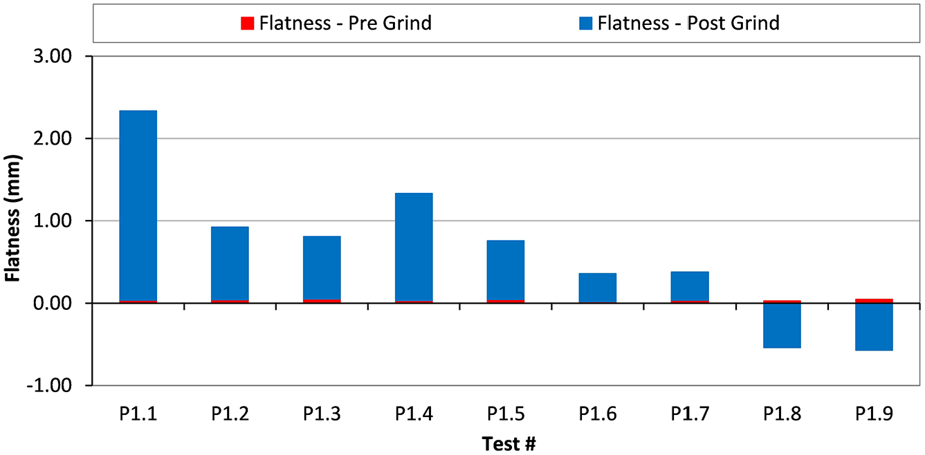
Phase 1 flatness variation.
Following an assessment of distortion, selected samples were measured for residual stress. The samples selected were for P1.1, P1.5, P1.6 and P1.8 and reflect the primary wheel variables under test (engineered ceramic grain, conventional alumina grain, cBN and diamond respectively). Combining both surface and depth residual stress measurements allowed the formulation of a surface to depth profile. When comparing key distortion metrics and the profiles in Figure 5, distortion and stress state can be mapped. In test P1.8 a clear compressive stress state can be seen in comparison to the other trials, resulting in a negative flatness direction. In tests P1.1, P1.5 and P1.6 a surface compressive regime is observed which quickly turns tensile and then returns to bulk at various depths beneath the surface. Test P1.1, which had the greatest positive distortion magnitude, demonstrates a highly dominant tensile stress state through to a depth of 250 μm, giving rise to the significant flatness change observed. A similar response is observed in the feed and cross feed directions, however in certain directions the difference is more significant. An assessment of grinding wheel thermal conductivity has not been carried out and the uncertainties of such values are reported by Morgan et al. 24 However, if you compare the relative values for the abrasive grain materials a trend can be deduced. For Al2O3, cBN and Diamond the respective thermal conductivities are assumed to be 35 (1.5–46), 24 240 (87–1300) 24 and 600 to 2000 25 W/m·K respectively with reported uncertainty. When compared to the relative thermal conductivity of the workpiece material (11.4 W/m·K), a shift in the balance between thermal and mechanical energy mechanisms is clear. With the Al2O3 based wheels, thermal energy transfer into the workpiece appears to dominate and with a move to smaller grain sizes and increased bond hardness this effect is exacerbated. With the cBN based wheels, a shift in residual stress profile towards a less tensile regime indicates a move in the balance between thermal and mechanical interaction. It is however evidenced that thermal energy partition into the workpiece dominates mechanical interaction. As the residual stress state with the diamond wheels shifts to a dominant compressive state it is clear that mechanical interaction is having the primary impact on the selected output metrics. Therefore, it is hypothesised that the diamond-based grinding wheels are less susceptible to thermal interaction and offer a route to compressive stress optimisation compared to their cBN super abrasive counterparts.
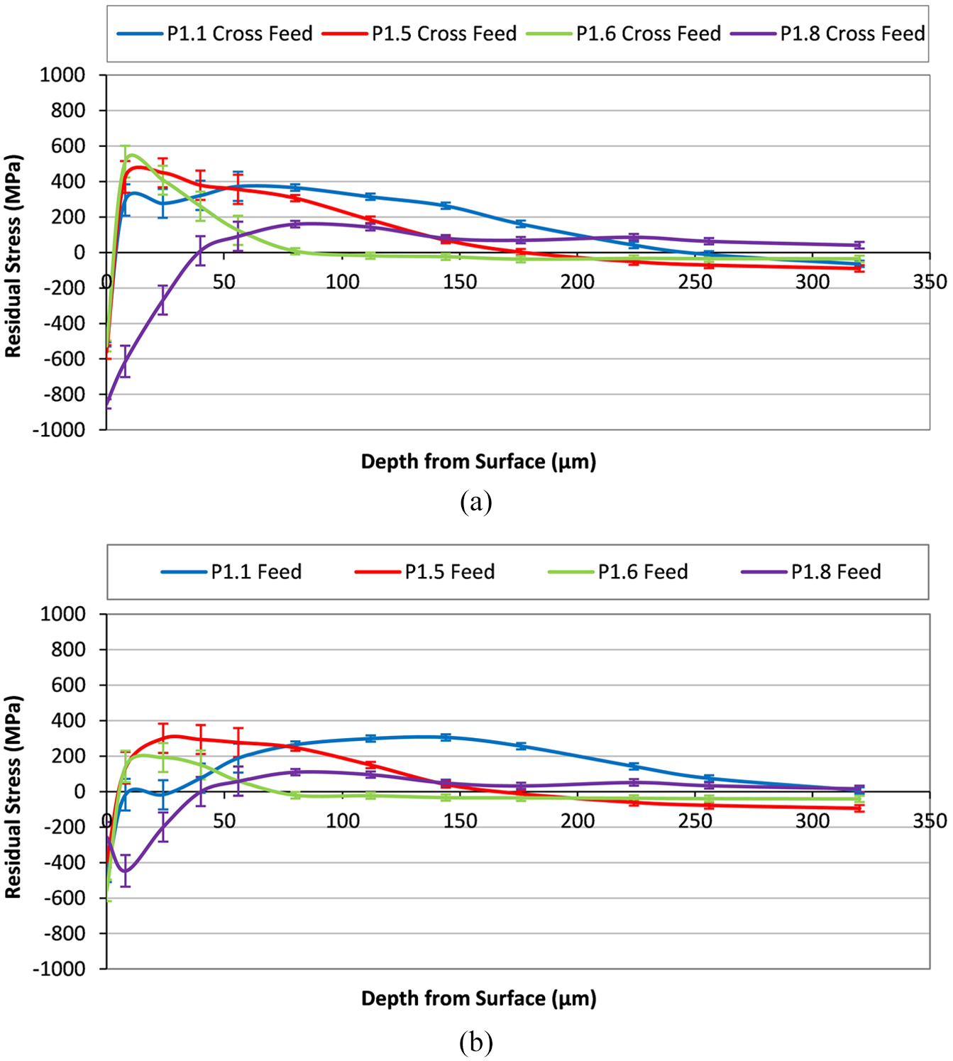
Phase 1 residual stress depth profiles: (a) cross feed direction and (b) feed direction.
Further to this, it was possible to link the profile flatness and the dominant stress state by considering the area under the stress depth profile. This was assessed in terms of an average stress depth and magnitude. Profile flatness direction change was observed to relate to the magnitude of dominant stress, rather than depth, that is, in P1.1, P1.5 and P1.6, small compressive surface regions are dominated by the sub surface tensile component and define distortion direction. Trends have been plotted in Figure 6 by considering the profile deviation in the feed and cross feed directions. The magnitude of tensile stress induced flatness changes was found to be predominantly influenced by the average depth of stress; i.e. greater depths generated greater deviation from the input condition. Insufficient dominant compressive regimes were encountered to be able to infer similar conclusions in their associated geometric changes. From the evidence presented, the balance in thermo-mechanical interactions between the grinding wheel and workpiece influence the intensity of the residual stress generated which in turn drive the level of distortion. Therefore, an opportunity to manipulate the selected process parameters to drive an optimised level of energy interaction and deliver a targeted output remains a strong hypothesis.
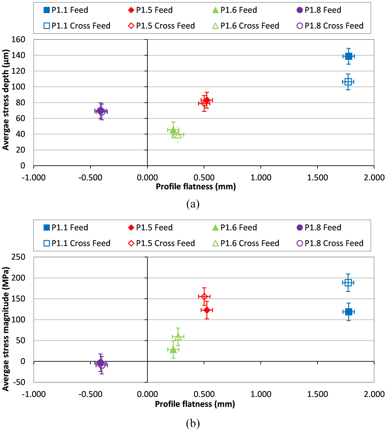
Phase 1 stress curve analysis against profile flatness: (a) average stress depth and (b) average stress magnitude.
With regards to surface topography (Figure 7), arithmetic mean roughness deviation (Ra) in the feed direction was fairly consistent and averaged 0.07 ± 0.035 µm. In the cross-feed direction, it averaged 1.31 ± 0.072 μm. Based on the wheel form selected and the step over (ap), there was an expectation to generate a scalloped surface with a theoretical Ra in the region of 1.08 µm. The dressable grinding wheels demonstrated close adherence to this theoretical value with any observed variation being a function of grain interaction and the observed wheel break down during tests. With the electroplated wheels, cross feed surface roughness was further dominated by the initial wheel topography and the absence of initial wheel conditioning. It is widely reported that electroplated wheels undergo rapid initial wheel wear and surface roughness reduction before reaching stable conditions. 13 As a result, the D151 EP wheels demonstrated the highest values with the vitrified Al2O3 wheels giving the lowest surface roughness where a harder and denser bond specification was used (A 60 I 9 V) indicating strong form holding capability and adherence to theoretical values.
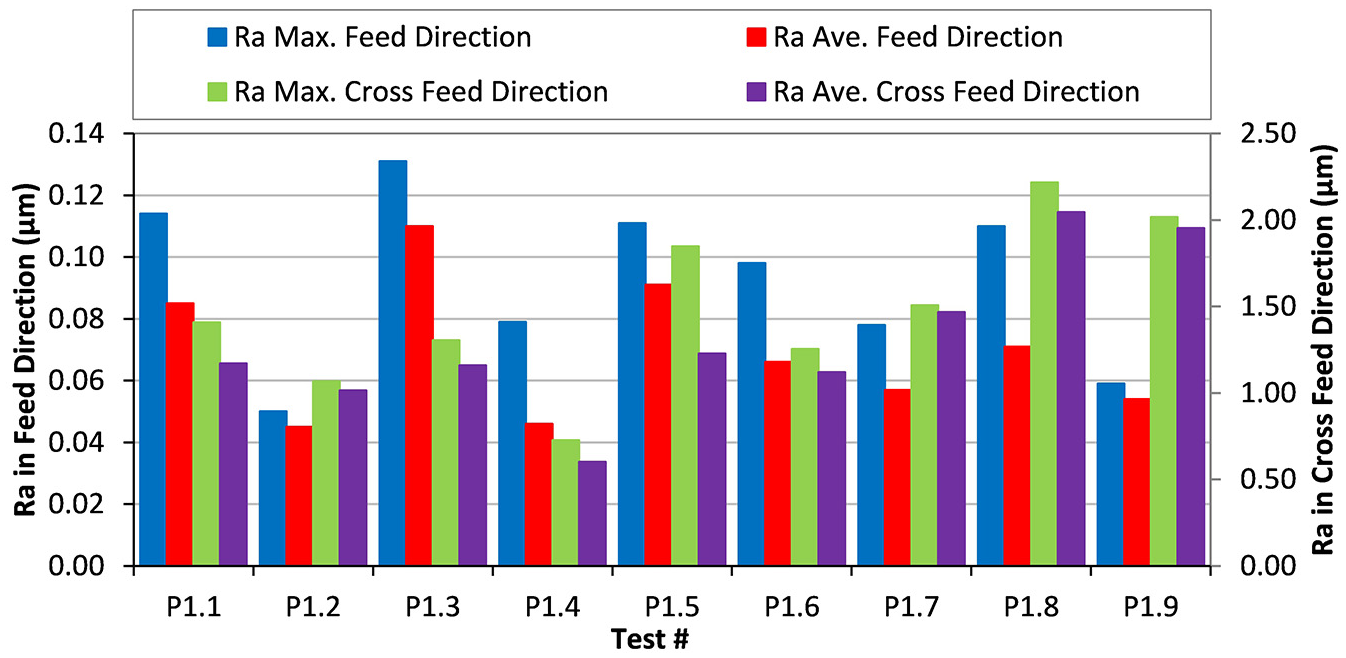
Phase 1 surface topography.
The micrographs in Figure 8 depict the wheel surfaces at the conclusion of testing for a selected wheel set. The wheel surface in P1.8 displays a typical electroplated wheel surface in an early wear cycle with no evidence of loading. The topography highlights the observation that the highest cross feed surface roughness was achieved with this wheel due to the course wheel surface condition in the absence of dressing or significant wear flat formation. This observation needs to be considered alongside the reported residual stress data whereby the single layer wheels are operating in an initial period where efficient cutting is dominant due to the presence of sharp cutting grains. Due to the non dressable nature of these wheels, the influence of wear mechanism and the resulting change in material removal mechanism needs to be more widely understood in the context of residual stress development over time. During single grit tests on Inconel 718, the variation in cutting action was reported across grains, cutting parameters and contact arc during scratch generation. 26 When extrapolated to a complex wheel surface various mechanisms and workpiece interactions can be in play during a wheel’s life. Wheels from tests P1.1, P1.4 and P1.5, seen in the shadowgraph projections, highlight the differences seen between tests in terms of profile breakdown which contributed to the differing surface roughness response. G-ratio was not a specific focus of the investigation and was not assessed for all trials. Due to the nature of the electroplated wheels, this assessment was not carried out. For dressable vitrified bonded wheels, assessment of the shadow graph projections was used to derive approximate G-ratios for the testing period. Values of G-ratio for these wheels were sub 0.2 with less than 1% variation between wheel types.
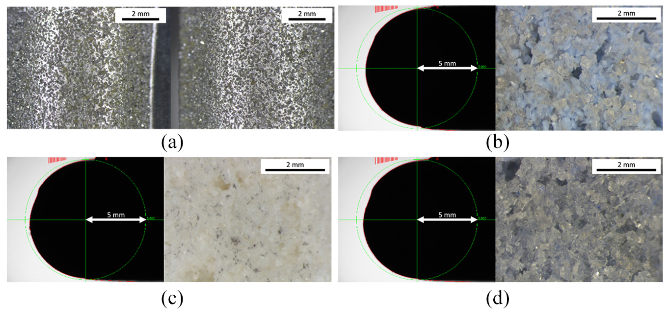
Phase 1 wheel surface images and shadowgraph projections: (a) P1.8 at end of testing, (b) P1.4 at end of testing, (c) P1.1 at end of testing, and (d) P1.5 at end of testing.
The test coupons ground with electroplated super abrasive specifications (P1.6 and P1.8) displayed very different responses. This seemed to contradict standard trends reported in literature with regards to residual stress states when cBN grinding. Conversely, assessment of sub surface integrity indicated similar results from cBN and diamond super abrasive products, with a distorted layer observed in the region of 7.5 to 11 μm (Figure 9) and a micro hardness profile (Figure 10) that displayed limited variation from the bulk material. Softening is generally associated with a heat affected zone from the thermal energy input of the grinding process. Literature frequently reports residual stress formation being a function of grinding temperature, however, the two abrasives have produced significant differences in stress formation. This suggests that the balance between thermal and mechanical interaction, which is driven by grinding wheel thermal conductivity and resulting energy partition as well as the mechanics of material removal, drive residual stress states without necessarily manifesting themselves as surface integrity defects.
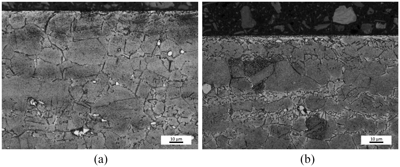
Phase 1 workpiece surface integrity: (a) P1.6 deformed layer and (b) P1.8 deformed layer.
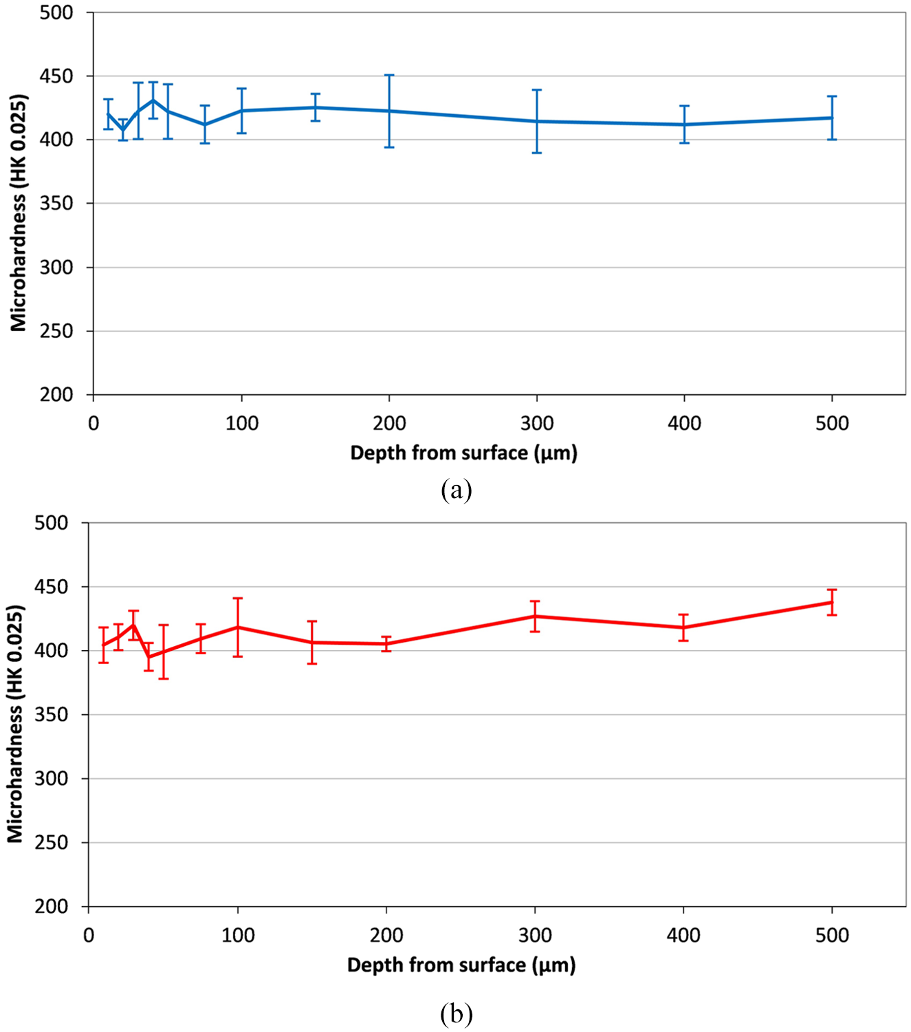
Phase 1 workpiece micro hardness: (a) P1.6 and (b) P1.8.
Test coupons P1.1 and P1.5 presented similar residual stress profiles but different distortion magnitudes. Assessment of sub surface integrity (Figure 11) indicated variation in response, although similar distorted layers were observed (5 μm). P1.1 showed evidence of redeposited material. Upon assessing microhardness variation (Figure 12), P1.1 showed evidence of hardening of 50 HK0.025 to a depth of 50 μm whereas P1.5 showed evidence of softening of 50 HK0.025 to a depth of 100 μm. The two responses show general forms typical of those reported by Zeng et al., 20 P1.1 represents a response of a dull tool under high material removal rates and P1.5 represents a case of high material removal rate and insufficient lubrication. The consistency of the response for P1.1 indicates that a combination of the hard bond and engineered grain is resulting in a combination of thermal and mechanical effects due to the resulting wheel wear mechanism. In test P1.5, the variability is relatively high indicating that stability in coolant delivery perhaps as a function of the high wheel porosity is dominating the response. A significant shift in grinding performance was reported by Magham et al. 27 when comparing fused and sol-gel Al2O3 abrasives. The conventional (fused) abrasive resulted in reduced specific grinding energies as a function of improved self-sharpening, whereas engineered (sol-gel) ceramic grains resulted in higher energy conditions and increased wear flat formation. It is evident from the trials conducted here that the move from conventional to engineered solutions can have a significant impact on metallurgical interactions with the workpiece manifesting in different residual stress states and subsequent component distortions.
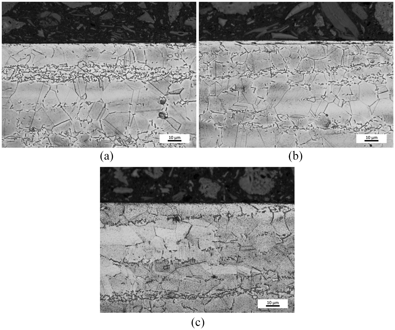
Phase 1 workpiece surface integrity: (a) P1.1 deformed layer, (b) P1.1 redeposited layer, and (c) P1.5 deformed layer.
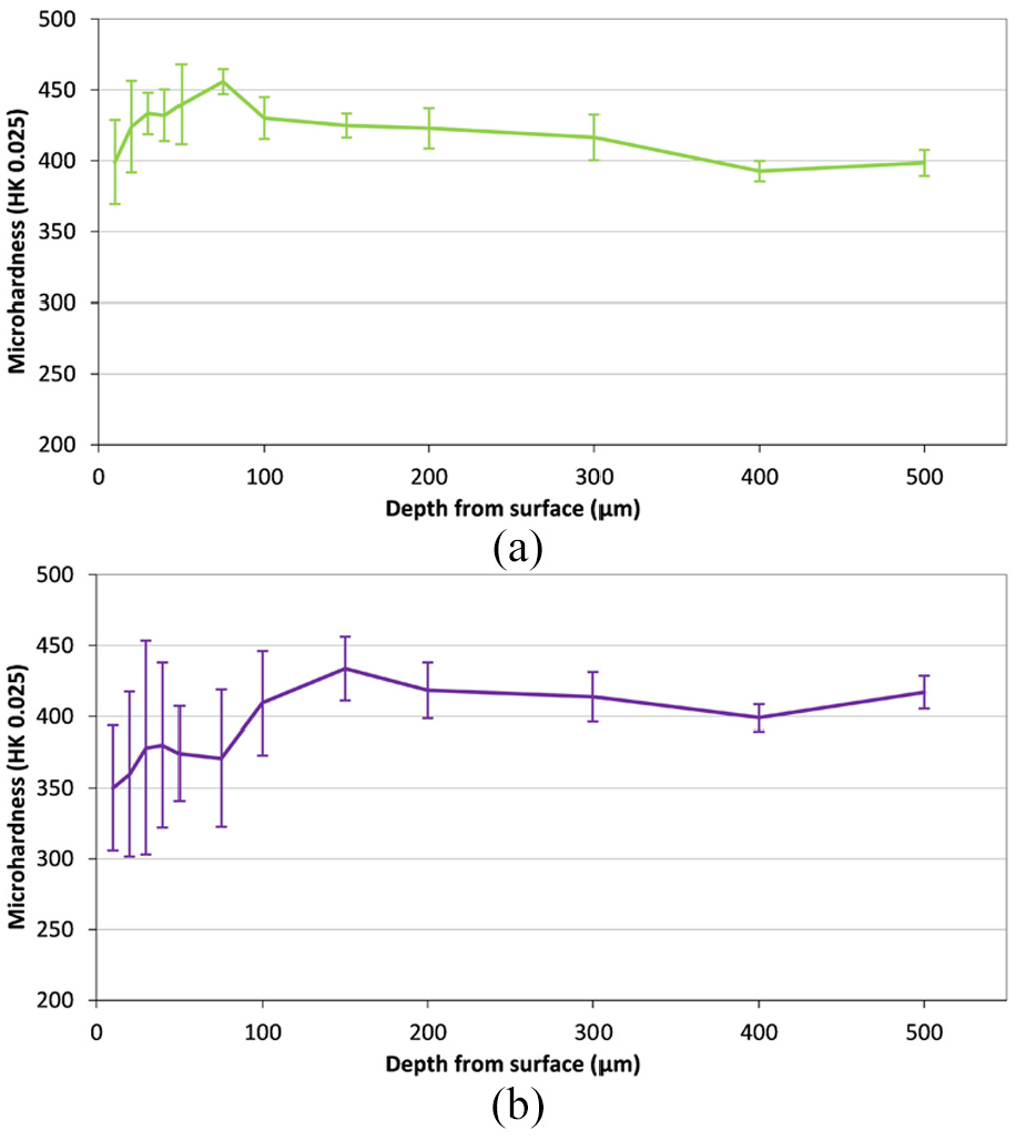
Phase 1 workpiece micro hardness: (a) P1.1 and (b) P1.5.
Stress and distortion response were observed to be a function of wheel technology. However, a clear link to sub surface integrity metrics was not seen. This indicated the importance of considering residual stress variation in line with wheel technology selection. Moving into Phase 2 trials, diamond based electroplated wheels demonstrated an ability to achieve beneficial compressive residual stress regimes. However, cBN abrasives demonstrated tensile regimes but evidence of reduced thermal impacts compared to Al2O3 grained vitrified wheels. The opportunity to manipulate this output via mechanical cutting parameters was therefore the focus of subsequent work.
Phase 2
Evaluation of flatness indicated a relative difference in performance between W6 and W7 with the former resulting in lower levels of distortion. Specification W6 possessed a larger diameter than W7, hence giving rise to surface speed discrepancies between the two products of 17 m/s, when factoring in the machine tool spindle speed limitations. This is anticipated to play a role in the variation in the results. Despite this difference, relative flatness measurements between test points within each wheel specification are similar. However, the smaller diameter and lower surface speed of W7 (Figure 13) has resulted in a greater tendency towards distortion directions that suggest tensile stress formation.
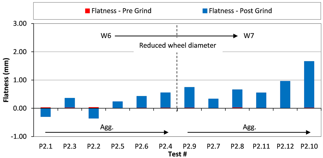
Phase 2 flatness variations, sorted by wheel and Agg.
Analysis of the distortion directions indicated that W6 tended towards compressive stress distortion directions and low levels of tensile stress. Specification W7 responded with a complete tensile response. From the distortion data collated, it can be hypothesised that the reduced cutting speeds and contact lengths are driving the shift in stress response towards dominant tensile conditions. The reduction in contact patch size with the smaller wheel specification restricts the heat transfer capacity into the grinding wheel and may contribute to the increased thermal interaction and tensile stress generation. However, the effect of grit specification variation between W6 and W7 cannot be discounted. The impact of wheel wear should also be considered although removal volumes are low and therefore impact should be minimised.
Considering the testing pairs detailed in Table 2, comparisons can be drawn with regards to the influence of grinding parameters. Within each wheel type, no significant trends could be extracted based on the manipulation of single parameter variables within the experimental design. The primary observation reflects the difference in wheel specification and the general trend observed for increasing aggression resulting in greater levels of distortion synonymous with tensile stress conditions. It is clear from this work that an increased data set is required to test the hypothesis of engineering a specific response from a given set of input process variables.
Cross feed residual stress depth profiles are presented in Figure 14. The measured data is in line with the distortion trends that have been discussed within this paper. The variation in test coupon response demonstrates the variation that can be achieved in residual stress response through a level of parameter manipulation. Preferable compressive stress regimes were achieved by increasing the wheel contact length, cutting speed and maintaining an Agg in the region of 45. Potentially detrimental tensile regimes were achieved through reduced wheel contact length, cutting speed and maximising Agg. This observation highlights a potential route to optimisation through management of the contact patch and the thermal conductivity of the grinding wheel specification to manage the heat partition within the process. It was also evidenced that parameters could be selected to minimise residual stress generated, therefore balancing both mechanical and thermal inputs, although the specific drivers for these changes could not be concluded beyond the more general aggressions trend.
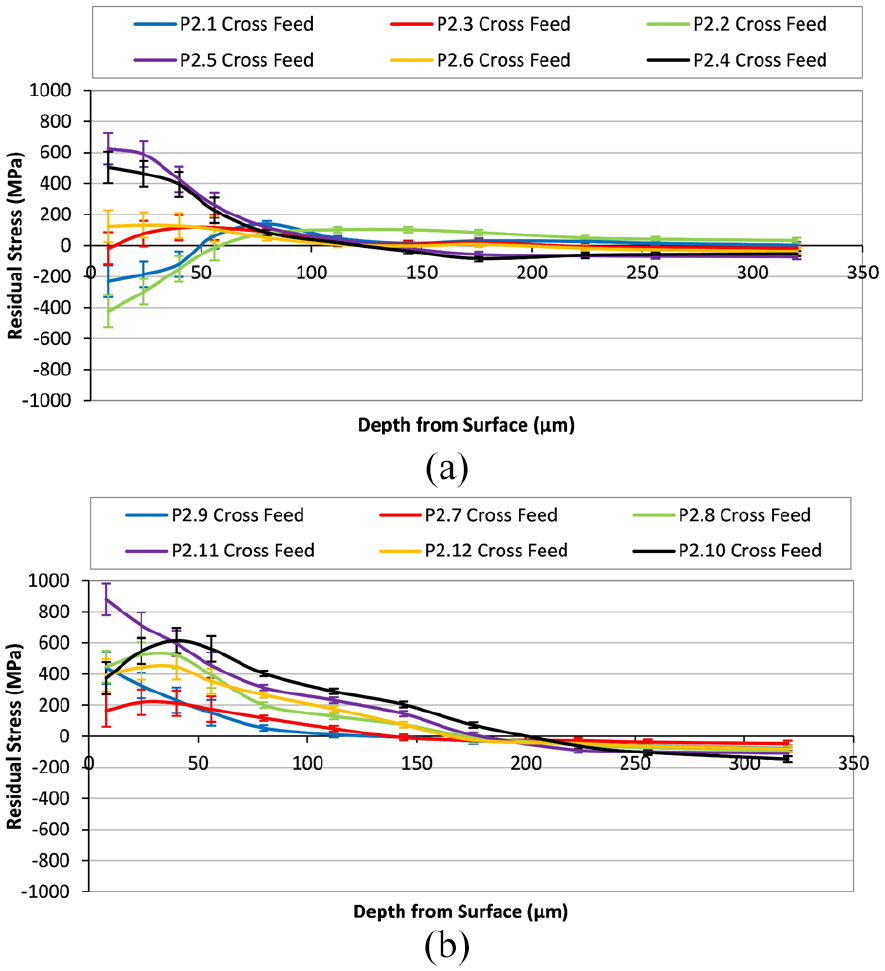
Phase 2 residual stress depth profiles: (a) W6 cross feed direction and (b) W7 cross feed direction.
Conclusion
From the work conducted, the following conclusions can be drawn:
Wheel technology has been shown to impact measured component distortion with a shift between super abrasives types, conventional Al2O3 wheels and engineered Al2O3 grains. Looking specifically at super abrasive wheel technology, a clear differentiation was observed between diamond and cBN whereby the former was able to achieve compressive residual stress states over the later
Compressive and tensile regimes have been generated but consideration needs to be given for the full stress profile and its depth as to the level of distortion measured. This is an important factor when considering future detection and optimisation strategies.
Clear relationships between typical subsurface integrity metrics used in industrial application and residual stresses were not observed. This is an observation that requires consideration when process optimisation is sought through wheel or parameter manipulation. Changes in residual stress profile, and therefore subsequent functional performance, may not only be indicated by typical surface integrity metrics such as micro structural evaluation.
With cBN abrasives, manipulation of grinding parameters via increasing Agg showed a relationship with increasing tensile stress regimes and distortion magnitudes. This has the opportunity to enable an engineered residual stress profile by manipulation of cutting parameters. Coupling this with a finite element modelling approach would enable definition of grinding parameters to manage distortions on components susceptible to form deviation. Further work is required in this area to generate a more detailed route to optimisation through manipulation of key process variables.
Footnotes
Appendix
Acknowledgements
We would like to thank Tyrolit Ltd and Saint-Gobain Abrasives Ltd for the support of grinding wheel products and John Webster (Cool Grind Technologies) for the design and manufacture of coherent jet coolant nozzle solutions.
Declaration of conflicting interests
The author(s) declared no potential conflicts of interest with respect to the research, authorship, and/or publication of this article.
Funding
The author(s) disclosed receipt of the following financial support for the research, authorship, and/or publication of this article: The authors would like to thank Rolls-Royce plc and AMRC members for funding to support this research.